Boden Build - 2015 Tacoma DCLB 4wd

tacozord

Adventurer
DeLorme InReach Explorer mount and power supply

TOOLS

I've used a Paladin Tools PA1302 ratchet crimper for many years, but Paladin was purchased by Greenlee Textron several years ago. This crimper utilizes interchangeable dies. The Greenlee crimper frame can be purchased at Amazon. However, if you search, you can find sets that include a specific die along with the frame.
Paladin1300Crimper_web800.jpg


In order to crimp butt splices and ring terminals, I used crimp die, PA2040, which can be purchased at Amazon.
PaladinPA2040CrimpAll_web800.jpg


To remove the Molex terminals from the connectors in case of a mistake, a Molex Mini-Fit Jr. terminal extraction tool can be purchased at Mouser. This is highly recommended, because you definitely will find yourself wanting to remove the pins.
MolexExtractionTool.jpg


The Molex Mini-Fit Jr. terminals are extremely small. Therefore, a special crimper is needed. This is the inexpensive version and can be purchased at Amazon or Mouser.
Molex_63811-1000_Crimper.jpg


To be continued...
 
Last edited:

tacozord

Adventurer
DeLorme InReach Explorer mount and power supply

INSTALLATION

Now that all the parts and tools are in order, I was ready to start.

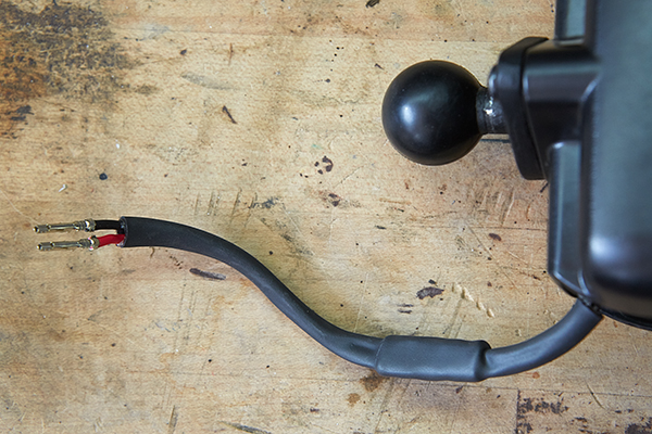
I began by cutting off the 12v adapter plug from the Powered inVehicle RAM Mount. I stripped back insulation to expose the individual wires. Although there are four pins on the cradle that connect to the back of the InReach Explorer, only the two outside pins are in use.

Next, I cut a red and black 18AWG wire a few inches long. All wires were stripped and crimped to the RAM mount wiring using 18AWG butt splices. In hindsight, I probably should have just left the wiring longer from the cradle and omit the but splices altogether. Then I could have simply crimped on the Molex terminals and be done with it. Oh well!
2015-09-05_DelormeInReachMount_Z2A4973_web600.jpg


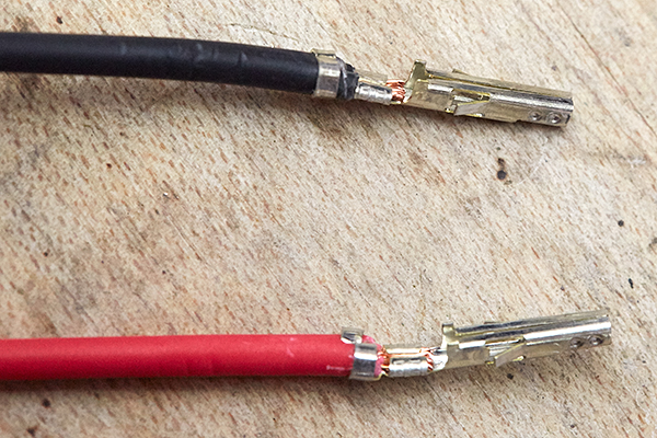
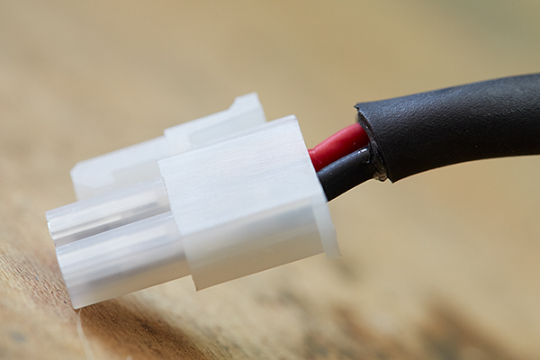
On the opposing end, I stripped and crimped on Molex female Mini-Fit Jr. terminals.
2015-09-05_DelormeInReachMount_Z2A4986_web600.jpg


I cut a piece of 1/2" heat shrink tubing, slid over the two wires and butt splices, and used a heat gun to shrink in place.
2015-09-14_DelormeInReachMount_Z2A5222_web600.jpg


I inserted the terminals into the female receptacle connector.
2015-09-14_DelormeInReachMount_Z2A5231_web600.jpg


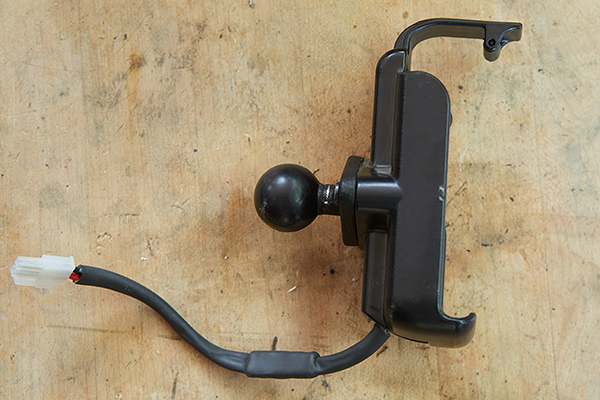
As you can see, I kept these wires very short. This was intentional so that I could remove the entire mount in the future if need be.
2015-09-14_DelormeInReachMount_Z2A5347_web600.jpg


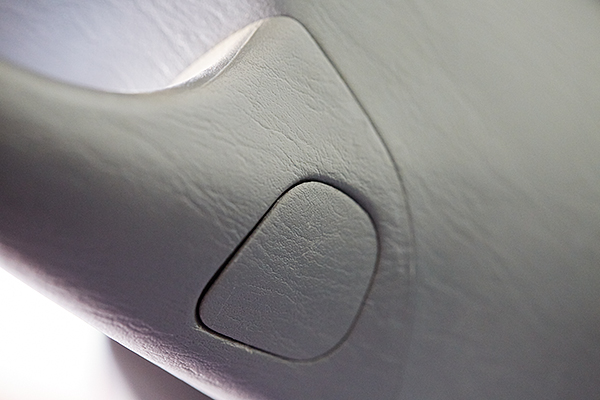
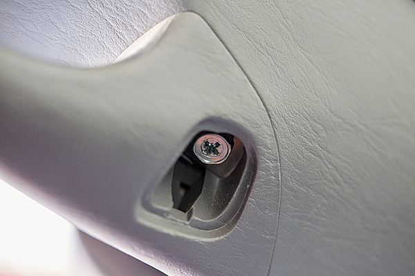
Next, I removed the A-pillar cover. The mounting bolt covers can be removed with your fingernail or a small screwdriver.
2015-09-05_DelormeInReachMount_Z2A4971_web600.jpg


After removing the two mounting bolts, the A-pillar trim cover was removed by simply pulling it away from the pillar.
2015-09-05_DelormeInReachMount_Z2A4972_web600.jpg


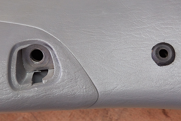
Next, I drilled a 3/8" hole into my A-Piller cover just below the lower handle bolt and pushed in the rubber grommet.
2015-09-08_DelormeInReachMount_Z2A5004_web600.jpg


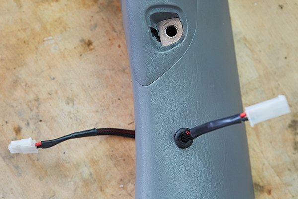
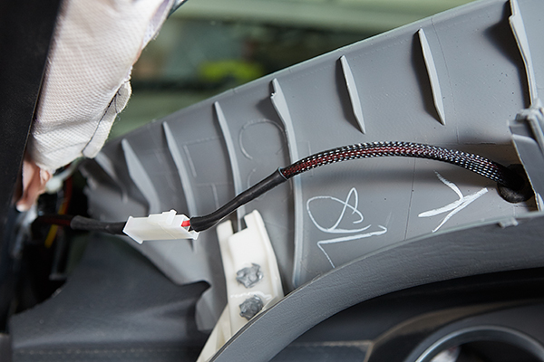
I needed to make another length of wire that traveled through the A-pillar trim. This was about 12" long with Molex connectors on either side. This way, the entire trim piece can be removed. The process involved installing a connector on one end and then covering the wires with braided sleeving and heat shrink. I inserted the wire harness through the rubber grommet before installing the terminals and connector on the opposing end.
2015-09-14_DelormeInReachMount_Z2A5252_web600.jpg


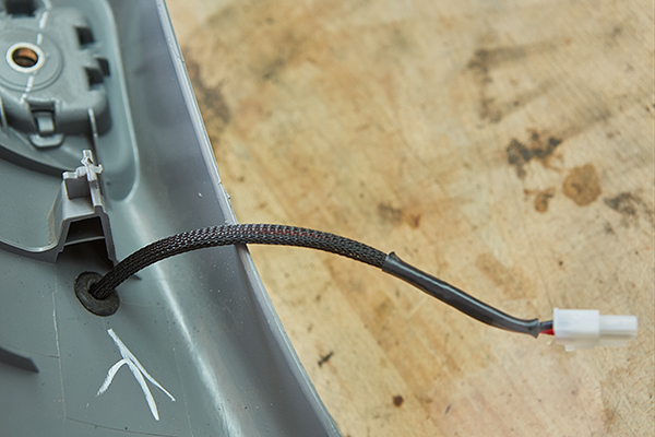
From the backside, you can see where the hole was made in approximation to the mounting hole.
2015-09-14_DelormeInReachMount_Z2A5259_web600.jpg


After this, I made the power supply wiring harness. I cut several feet of wire and installed Molex terminals and connectors to both ends. As before, I used braided sleeving and heat shrink to protect the wiring and group them together.

I routed the wiring harness up through the dash and secured it in place at the bottom of the A-pillar with a cable tie mount and zip-tie. I kept the zip-tie loose, which was intentional so that the wiring could be maneuvered as required. This made installation and removal of the A-pillar trim easier. (By the way, an electricians fish-tape or coat hanger aids in navigating the wire up behind the dash and to the A-pillar.)
2015-09-14_DelormeInReachMount_Z2A5250_web600.jpg


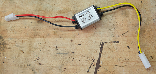
I installed Molex connectors to both the input and ouput sides of the 12v-to-5v converter.
2015-09-14_DelormeInReachMount_Z2A5446_web600.jpg


The converter was mounted with 3m double-sided tape to the backside of the under-dash trim panel. The output of the converter connects to the wiring harness routed up behind the dash and to the A-pillar.
2015-09-08_DelormeInReachMount_Z2A5078_web600.jpg


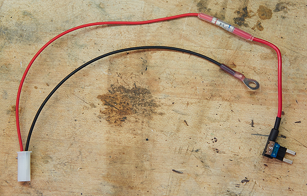
To connect the input side of the converter to power and ground, I made another wiring harness. A Molex connector was installed on one end with both wires. For the opposing ends, the red wire connected to a fuse-tap for power, and the black wire terminated with a ring terminal for ground.
2015-09-14_DelormeInReachMount_Z2A5437_web600.jpg

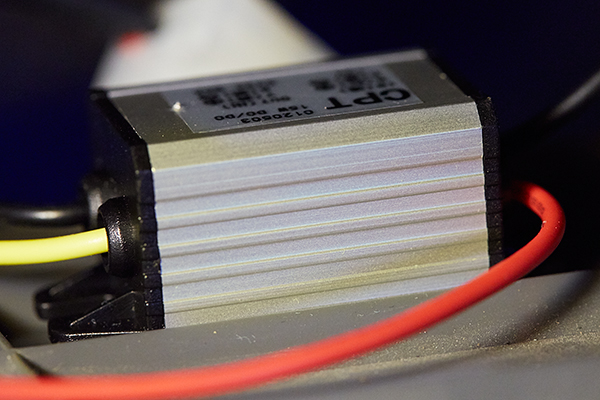
The 12v-to-5v converter was attached to the backside of the trim piece below the steering column. Ground was terminated at a mounting bolt. This wasn't an ideal spot for grounding, but will suffice for the time being. I ultimately plan to install an additional fuse block within the cab.
2015-09-14_DelormeInReachMount_Z2A5462_web600.jpg


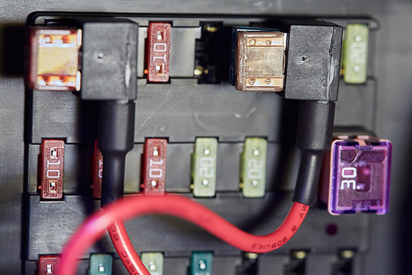
For the 12v source, I used a fuse tap.
2015-09-08_DelormeInReachMount_Z2A5086_web600.jpg


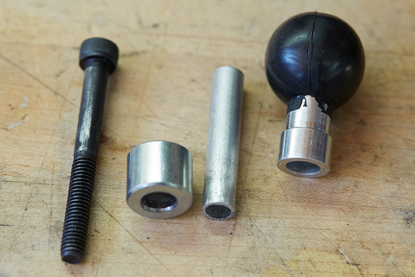
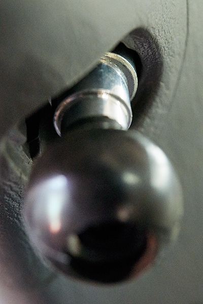
To re-install the A-pillar trim, I needed to do a little fabrication. I first bored the hole in the zinc spacer from 1/4" to 5/16". Then I cut a length of aluminum tubing so that it spanned the length of the shaft in the RAM ball mount and the spacer.
2015-09-08_DelormeInReachMount_Z2A5035_web600.jpg


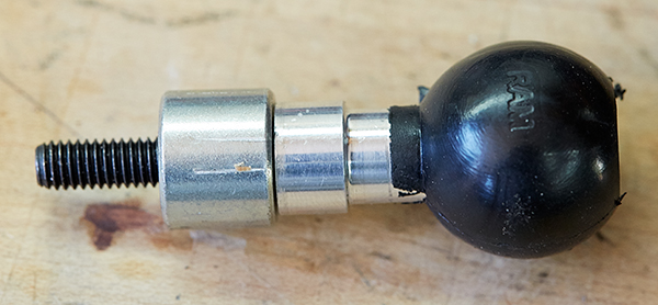
When put together, it looked like this.
2015-09-08_DelormeInReachMount_Z2A5044_web600.jpg


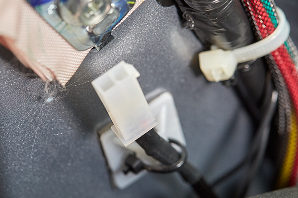
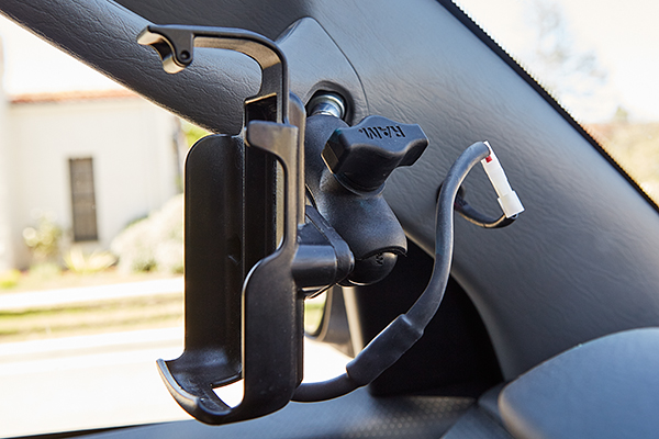
The A-pillar trim was re-installed by first connecting the wiring together with the Molex connectors
2015-09-14_DelormeInReachMount_Z2A5282_web600.jpg


After securing the top bolt, I used the RAM ball mount with spacer for the bottom mounting hole.
2015-09-08_DelormeInReachMount_Z2A5050_web600.jpg


The cradle was mounted using a short double socket arm, RAP-B-201U-A, and positioned in place.
2015-09-17_DelormeInReachMount_Z2A5595_web600.jpg


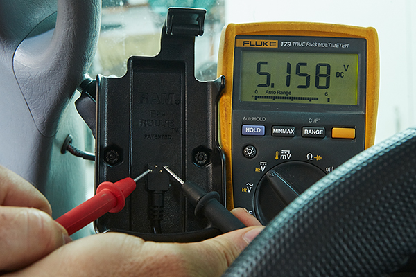
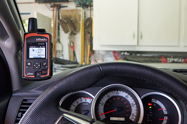
Using a volt meter, I tested that I correctly had 5 volts on the two outside pins.
2015-09-14_DelormeInReachMount_Z2A5426_web600.jpg


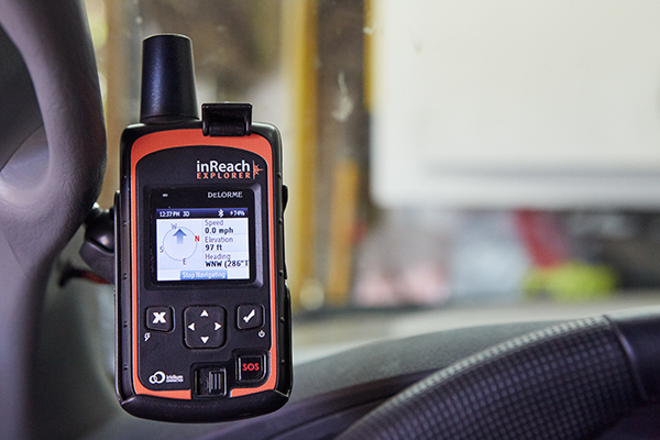
With the DeLorme InReach Explorer in place, the GPS unit received power whenever the ignition was on.
2015-09-08_DelormeInReachMount_Z2A5090_web600.jpg


Success! I now had a secure mount for my DeLorme InReach Explorer with a dedicated power supply. I was very happy with the results.
2015-09-08_DelormeInReachMount_Z2A5091_web600.jpg
 

tacozord

Adventurer
That Flippac looks awesome. Fits perfectly on there. Do you have any plans to change the color of the Flippac?

At the moment, no. Although used and cheaper than new, it still cost me a few bucks. Plus, I'd rather spend on a few other things at the moment. There's some more electrical, and I'd like to outfit the inside. So most of my energy will be spent there. As far as painting down the road, perhaps. This shell is showing it's age for being three years old. So eventually I'll paint it, and I'll decide then if a color change is in order.
 

tacozord

Adventurer
XM antenna mod

2015-09-30_Tacoma_XM-Antenna_Z2A5850_web600.jpg


I recently purchased a used Flippac for my 2015 Toyota Tacoma. Although it fit my truck, there was one detail that required modification, the XM radio antenna. Had the Flippac been purchased new, it would have accommodated the "sharkfin". Unfortunately, the shell I purchased didn't allow enough clearance.
2015-09-29_Tacoma_XM-Antenna_Z2A5798_web600.jpg


Therefore, I was forced to remove the antenna, but this left two holes in the roof. My choices were to cover the holes with something or reinstall a shorter antenna. My plan was to modify my current antenna and reinstall.
2015-09-30_Tacoma_XM-Antenna_Z2A5845_web600.jpg


Once home, I began by disassembling the antenna. As shown, the electronics are limited to about 1/2" of vertical space. This allowed me to cut the antenna shorter.
2015-09-29_Tacoma_XM-Antenna_Z2A5787_web600.jpg


With a plan in place, I marked a line about 1 1/8" up from the bottom.
2015-09-29_Tacoma_XM-Antenna_Z2A5806_web600.jpg


I used a Dremel tool with a saw blade to cut off the top.
2015-09-29_Tacoma_XM-Antenna_Z2A5816_web600.jpg


Using various grits of sandpaper, I smoothed the cut surface.
2015-09-29_Tacoma_XM-Antenna_Z2A5820_web600.jpg


I used plastic epoxy to fill in the cut off area. To keep it level, I filled up the inside of the housing with epoxy while it was upside down on parchment paper. I smeared a thin layer of paste wax on the paper beforehand hoping it would prevent the paper from sticking. It worked.

You'll notice that the epoxy is cream colored. I wanted to use black, but I couldn't find any black plastic epoxy locally and didn't want to wait for it to be delivered. Besides, it didn't really matter, because it would only be visible from the air.
2015-09-29_Tacoma_XM-Antenna_Z2A5825_web600.jpg


After the epoxy hardened, I sanded smooth.
2015-09-30_Tacoma_XM-Antenna_Z2A5839_web600.jpg


Last, I reassembled and installed. Job done!
2015-09-30_Tacoma_XM-Antenna_Z2A5850_web600.jpg
 

P2W

Observer
You'll notice that the epoxy is cream colored. I wanted to use black, but I couldn't find any black plastic epoxy locally and didn't want to wait for it to be delivered. Besides, it didn't really matter, because it would only be visible from the air.
2015-09-29_Tacoma_XM-Antenna_Z2A5825_web600.jpg

I like that idea.
I've used JB Weld as a filler as well when modifying gun stocks and bedding actions. Johnson's paste wax makes for good release agent.
 

mrothwell

New member
I love that flippac! Any pics of the inside? How hard was the install into the truck? Any issues/annoying rattles driving on washboard dirt roads?
 

kmacafee

Adventurer
One of the things that bugs me about this truck was the ambient outside temperate gauge being tied to a HD radio station through the Entune Audio system. Really frickin' stupid in my opinion. I'd literally be up in Valencia, and it would tell me the temperature in Santa Monica, which is 30 miles away!!!

Anyway, I came real close to installing a very simple temp gauge for only a few bucks. However, I came across a post on Tacoma World that Bob's Automotive Mirrors had a rear view mirror with autodim, compass, temp gauge, and Homelink. And...it came with a connector to tie into the existing wiring harness. Brilliant!!! I was sold.

2015-02-03_Tacoma_Z2A0755_web800.jpg

Greetings and thanks for such great detailed write ups.

I have a 2012 Tacoma which came with the stock electric mirror -- looks very similar to the one you purchased. I looked at Bird Dawgs mirror riser but they state its only for the standard non-electric mirror. It looks like you were able to make it work. Any issues or was it plug and play?

Thanks
 

tacozord

Adventurer
I like that idea.
I've used JB Weld as a filler as well when modifying gun stocks and bedding actions. Johnson's paste wax makes for good release agent.

Thanks for the tip with JB Weld. I'll have to keep that in mind. And yes, the paste was worked better than I thought. This was my first attempt at something like this.
 

Forum statistics

Threads
185,819
Messages
2,878,551
Members
225,378
Latest member
norcalmaier
Top