Sabre
Overlanding Nurse
Earlier this year my 2001 Ltd developed a bit of noise up front. Stopping on the freeway offramp and laying a hand on the wheels confirmed my suspicions: the left front was way, way hotter than the right side. I had a wheel bearing on the way out. Not bad, considering the abuse this poor rig has sustained (dust & water) in 120,000 miles. I ordered a new set of front bearings and set out to swap them out. Though it may seem a bit daunting, it really is a straightforward procedure. Note that I'm just a halfway handy home mechanic. I don't tear into engines, don't do major rebuilds, but wanted to demonstrate that this task is within the abilities of anyone who is reasonably handy. You also don't need any special tools. I used a small straight-blade screwdriver, a needle-nosed pliers ("snipe-nosed" if you have an odd accent), a couple of socket wrenches & open end wrenches, a torque wrench, and a hammer. DISCLAIMER: this is NOT the procedure if you have a Sport. That is a different beastie entirely.
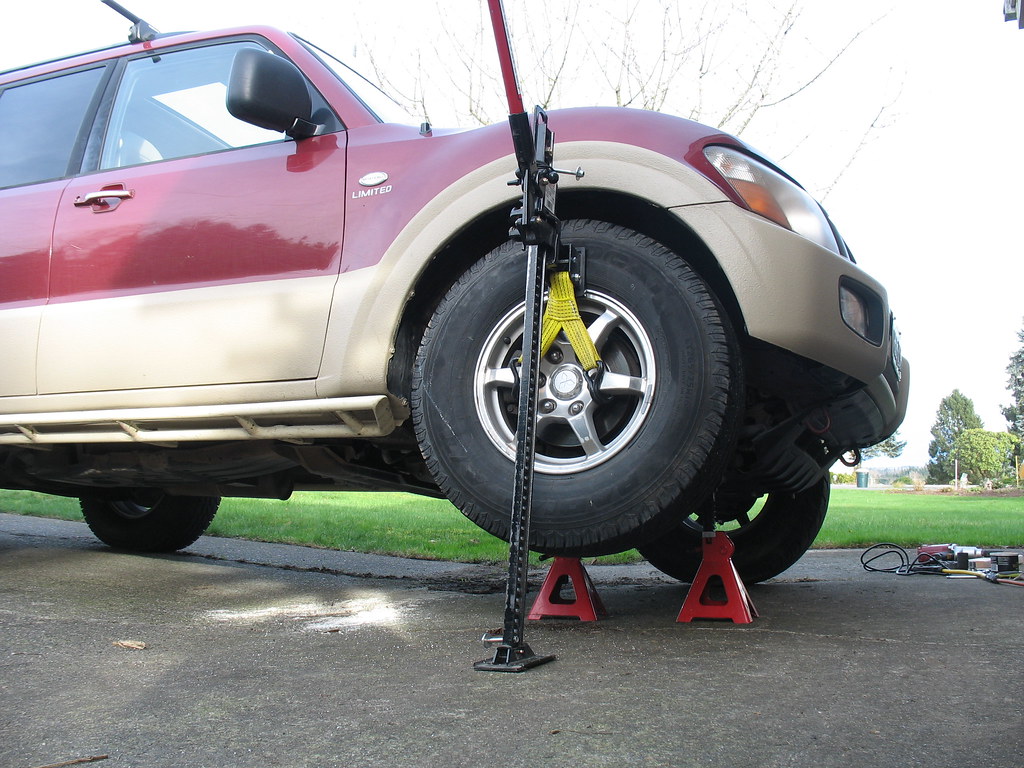
The first step is to jack up the front. Note that this pic shows the right front being jacked up, although the procedure itself is shown on the left (driver) side. Get it on some really safe, solid jackstands. Don't use a stack of wobbly chunks of lumber, you cheap bugger. Safe enough? OK, now remove the wheel.
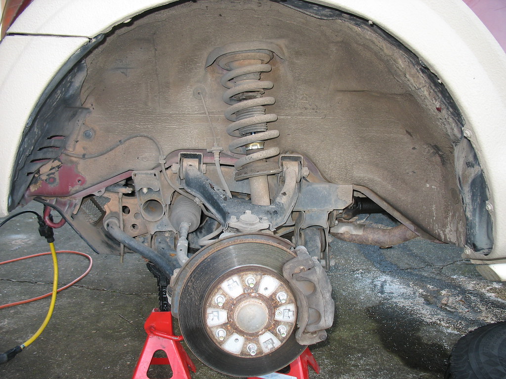
Here's what you'll see; again, we're on the LEFT side now.
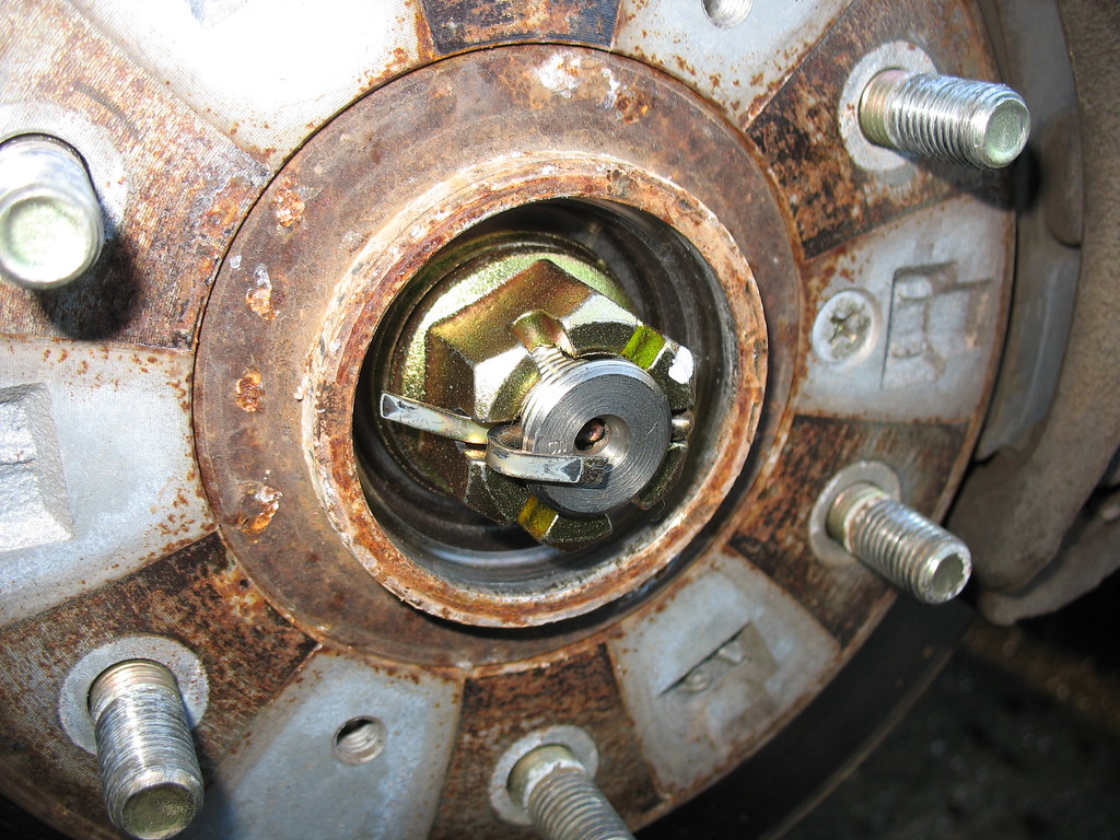
Use a screwdriver to pry off the dust cap on the end of the axle. Removing the cotter pin and the axle nut is pretty straightforward.
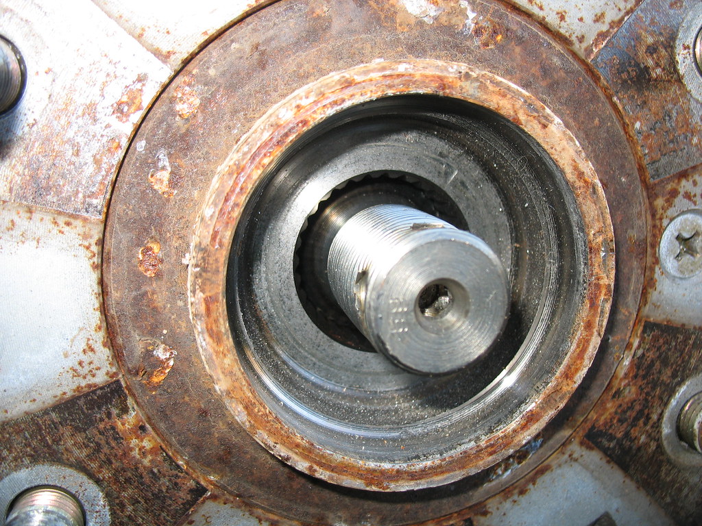
Now, to free the axle itself you tap the end of it with something. DO NOT start bashing away with your favorite hammer! What you want to do is to tap the axle back without buggering those lovely threads. Put a piece of scrap wood over it and then wail away with the old claw hammer. No, seriously...it doesn't take much of a tap and you'll soon see that the axle floats in and out quite nicely.
OK, let's get a picture of the lay of the land. Here's the left, front suspension viewed from the front.
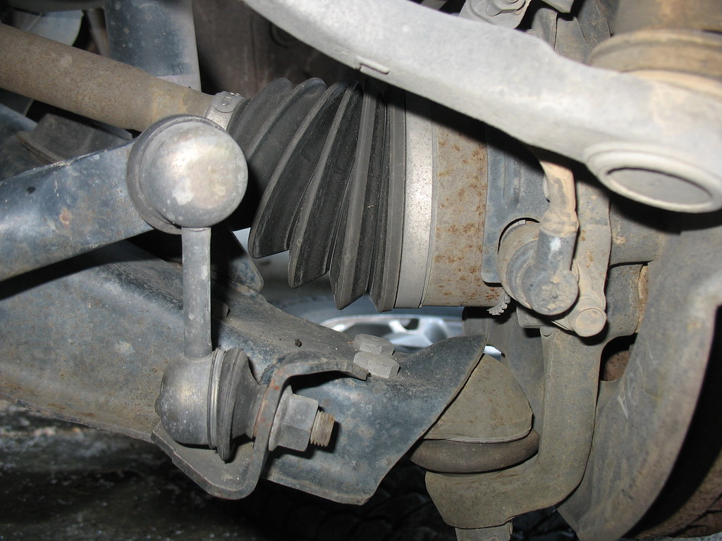
Right there in the middle you can see the axle angling down from the front diff. Remember, we're on jackstands here with the suspension at full droop, so the axle angles down pretty dramatically. Note that the CV joint, hidden beneath the rubber bellows boot thingy, is flexing at a pretty good angle. The reason that these rigs are limited to a suspension lift of 1.5 to 2 inches is because of this CV joint. Exceeding this angle will both tear those boots apart and wear the CV joints prematurely. But it's OK, because these massively competent beasts don't need much lift, anyway. We're overlanders, not mudders or crawlers, right?
OK, you can also see the tie rod end kind of out of focus there in the upper right. This is going to come apart next. You can also see the toothed "sprocket" of the ABS system with the wheel speed sensor visible there looking like a spark plug wire. This sensor will be removed shortly, too. At the very bottom is the lower ball joint; its twin, the upper ball joint, is out of the picture at the top. These both get separated, too. But first, let's look at that tie rod end.
Here's the tie rod after separation. Please note a few details about this.
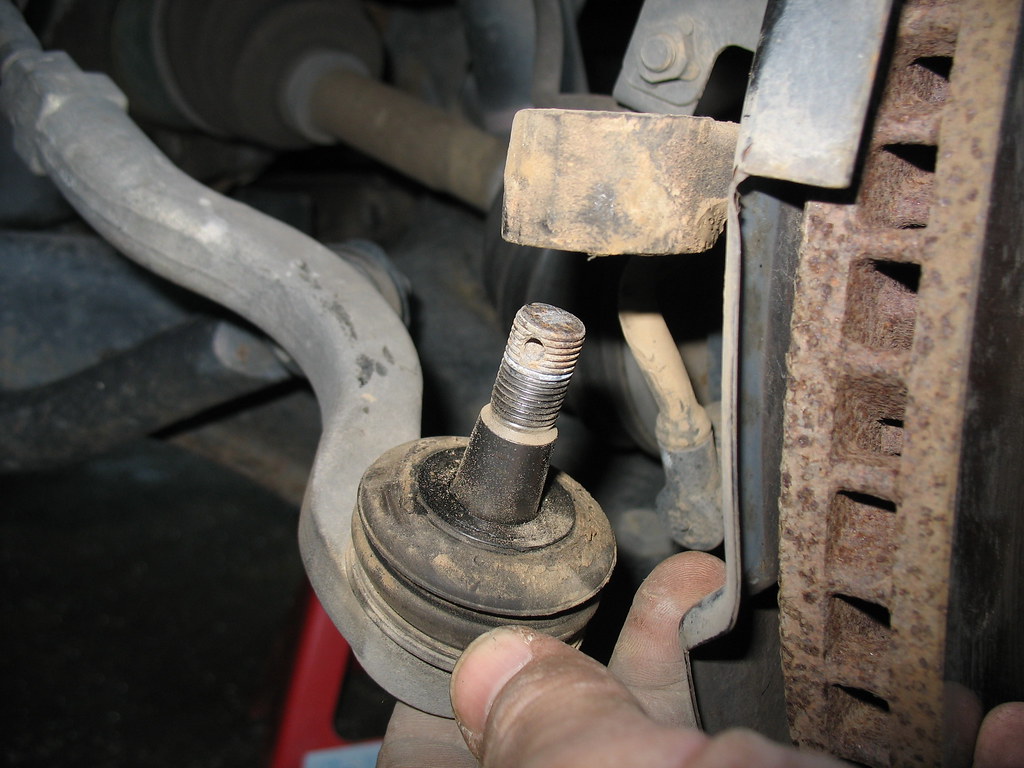
After removing the cotter pin and retaining nut, this joint is easily separated IF you know the secret. Ladies and gentlemen, one of my primary motivations in posting this thread is to save you the aggravation that I suffered. Let me put your fears to rest and share my new-found knowledge, so that you might have a joyful experience. In other words, do as I say and not as I do!
You DO NOT hammer on the upper, threaded end! Want to know what will happen if you do? You'll bugger those threads! Wanna know how I know this? Want me to teach you some new swear words?
The simple secret is contained in the fact that this is a TAPERED joint. Look closely at the shaft below the threaded area. Note that it's actually a gentle taper. It fits in turn into a slightly tapered hole. To free such tapered spindle joints, you tap on the SIDE of the joint, 90 degrees to the axis of that threaded shaft. Feel free to bang away like a madman, cuz you're not going to break anything hitting the side of that heavy casting. Of course, if you go off course and smash those lovely, delicate threads, you're on your own. Don't say I didn't warn you. What I recommend is to leave that retaining nut loosely in place while hammering the side of the casting. If your aim isn't true, you'll protect the threads by keeping the nut there.
OK, next we'll get that wheel speed sensor out of there. It's held in place by a stamped metal part that is easily removed by backing out a few bolts. Easy-peasy. Since you're not going to unplug anything, just tie the sensor up out of the way with wire, duct tape, or your bubble gum.
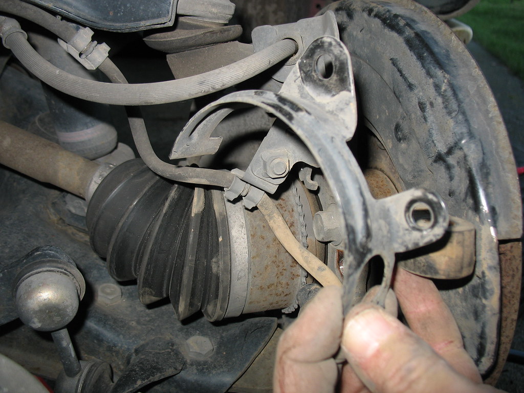
Oh, you can see the upper ball joint at the top of this picture, just above the brake hose. Be patient...we'll get to this.
Now we'll remove the brake caliper. You don't need to open up the brake system or do anything at all to the brakes for this procedure. Of course, they always tell you in every set of instructions that I've ever read, "never apply the brakes when the caliper is removed cuz you'll push the pistons out of place and make a horrible mess." So, you know, don't hop in the rig and apply the brakes, m'kay? Oh yeah...the caliper bolts are obviously big and strong. Don't destroy your knuckles when the socket wrench slips...proceed with caution. Really, it's simple.
Once the caliper mounting bolts are out, you'll find that the pads are still gripping the brake rotor (disc) and that the caliper is sort of stuck. It's safe to just push the pads back in a bit, loosening their grip on the rotor. You can do this by putting a little twist or rocking motion on the caliper to slowly shove those pads back against their pistons. Heck, you can even jam a screwdriver in there and pry them back a bit. Oh yeah...this is the part where instruction manuals tell you that you have to remove the top of the master cylinder reservoir and place a piece of clean cloth over the top. You know, because, like, you're going to be pushing massive quantities of brake fluid backwards up the lines into the reservoir. Except that...um, no, you're not, and you can just leave that master cylinder reservoir alone. Of course, if your car breaks it's not my fault. I'm not a licensed mechanic and can't be held responsible for your potentially fatal brake failure. But, you know, it's gonna be fine.
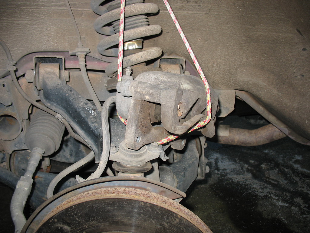
Oh yeah...hang that big, heavy brake caliper up there with a nice bungee cord or something. You don't want it hanging down getting in your way, and you don't want it tugging on that rubber brake hose.
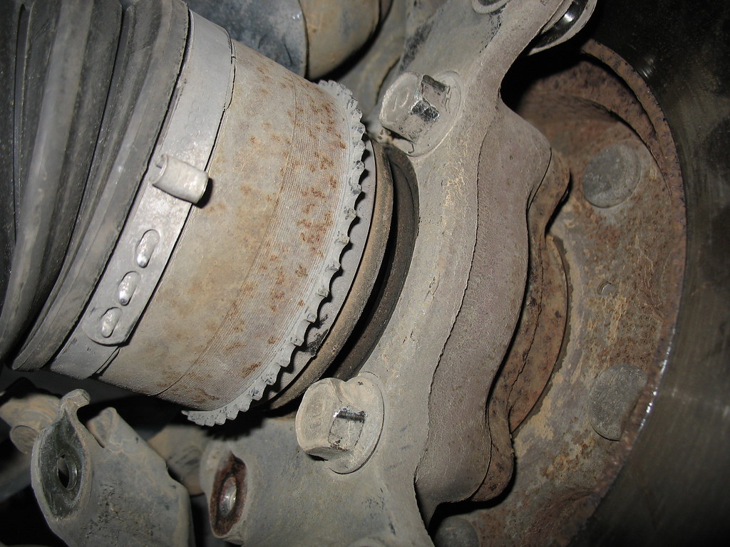
Here's a better look at that wheel speed sensor sprocket with part of the stamped metal bracket moved out of the way (lower left corner of pic):
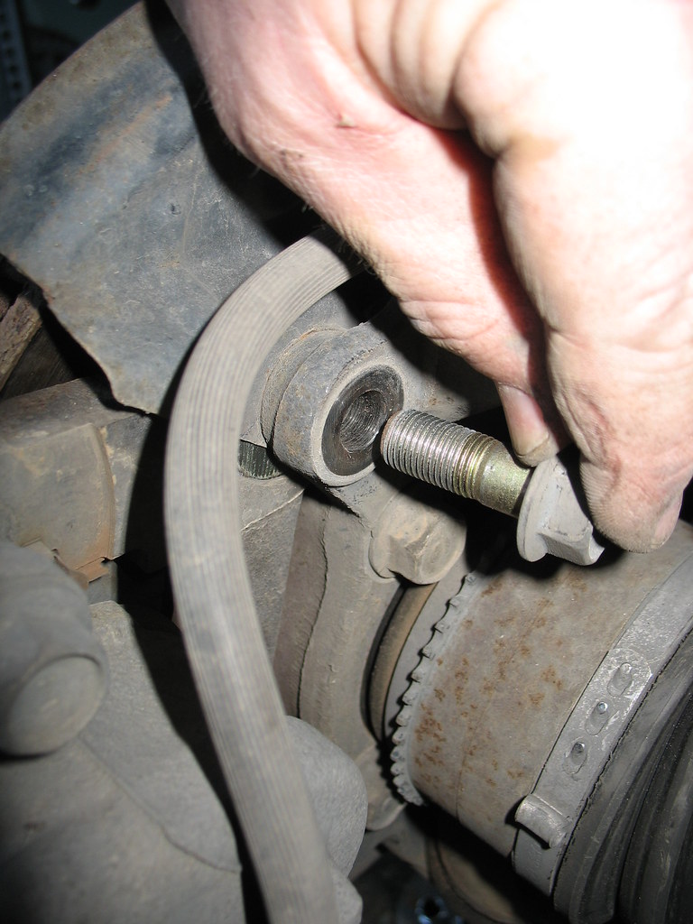
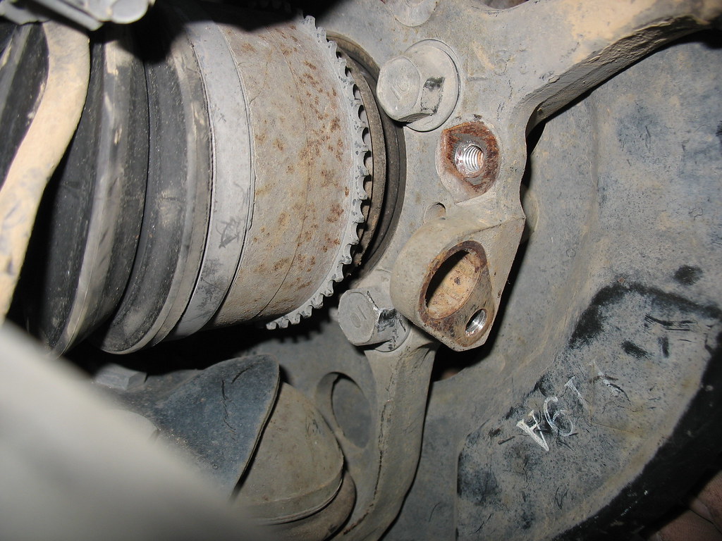
And this picture shows a good view of where that speed sensor usually lives: in that hole about the diameter of a finger, right next to the threaded hole that is used to hold it in place:
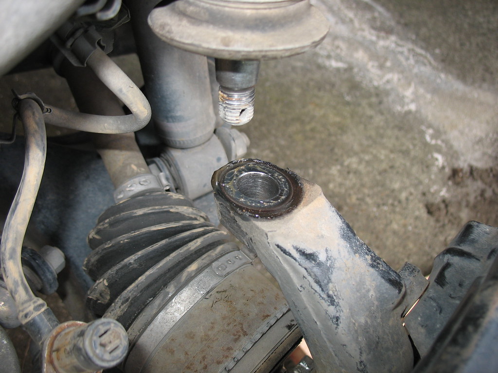
OK, viewed from above, there's the speed sensor lying loose there in the lower left corner. And, FINALLY, there's the upper ball joint. Note that I've done all the hard work for you...it's already had the cotter pin & retaining nut removed and it has already been separated! And you didn't need one of those pickle fork tools or anything else more complicated than a hammer, now that you have been gifted the secret of tapered spindle joint separation. Yeah, it's tougher than the tie rod end. Duh! No worries...just bang away until it suddenly surprises the heck out of you and drops out of the joint. Cuz that's exactly what happens!
OK, ready for the final push? Here goes. Repeat this with the lower ball joint. Same procedure: cotter pin, retaining nut, hammer like a caveman on the side of the casting. Only THIS time, it really will drop right off when it separates, because absolutely nothing is holding it together at this point. Be ready to catch the whole thing. Really, no kidding. Be ready. And it's heavy.
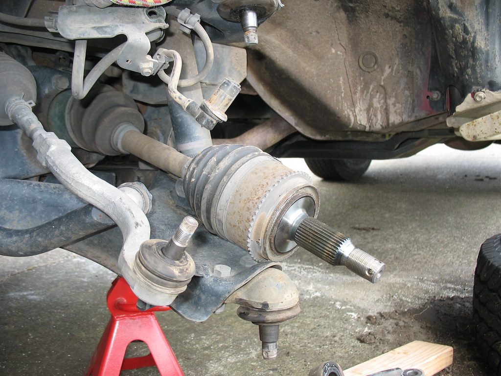
So, this is the massive thing that just fell into your hands. Let's study it.
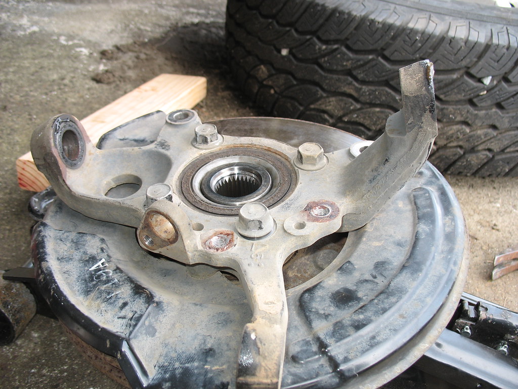
It's lying there, rotor-side down. The upper casting is called the spindle. You see the lower ball joint fitting on the left, the upper on the right, and the tie rod end fitting extending toward us in this picture. There's that empty hole where the speed sensor was, and those threaded holes where the little metal stamping was removed. The big black round thing under the spindle is the rotor dust cover. At the center of the spindle you can see the inner end of the hub itself. Note the little splines that mate with the axle splines. The Toyota guys are always talking about the number of splines that they have. We Montero guys don't need to count our splines because we have have plenty and they never break.
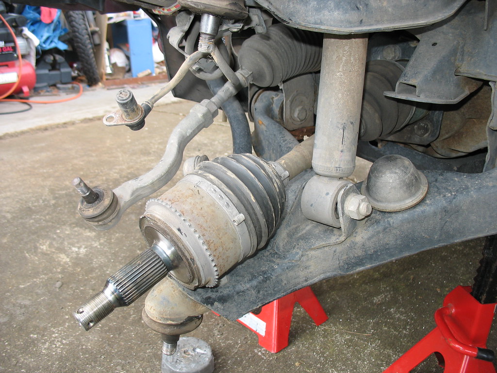
Here's another view of your truck since you removed this essential bit. Viewed from the rear, you can see how the lower shock (well, it's called a strut in the front) mount looks. You can also see the bump stop...that black rubber dome-shaped thingy...that limits upward travel under extreme spring compression. Some people think that you can remove this and replace it with a low-profile bump stop. These folks think that your articulation will improve. Guess what? It's a Gen III Montero. It has four-wheel independent suspension. It ain't never gonna have spectacular articulation. You've picked the wrong vehicle if you want to win a flex-posing contest. Just go out and drive it up the trail that the Toyota guys struggle on. Spend your money on some good beer to enjoy at the top of the trail. Chuckle to yourself at the $14,000 suspension mods on the JK.
OK, this part is sort of cool. Want to know what's holding your brake rotor (disc) on to your hub? Only this little screw. Unscrew it.
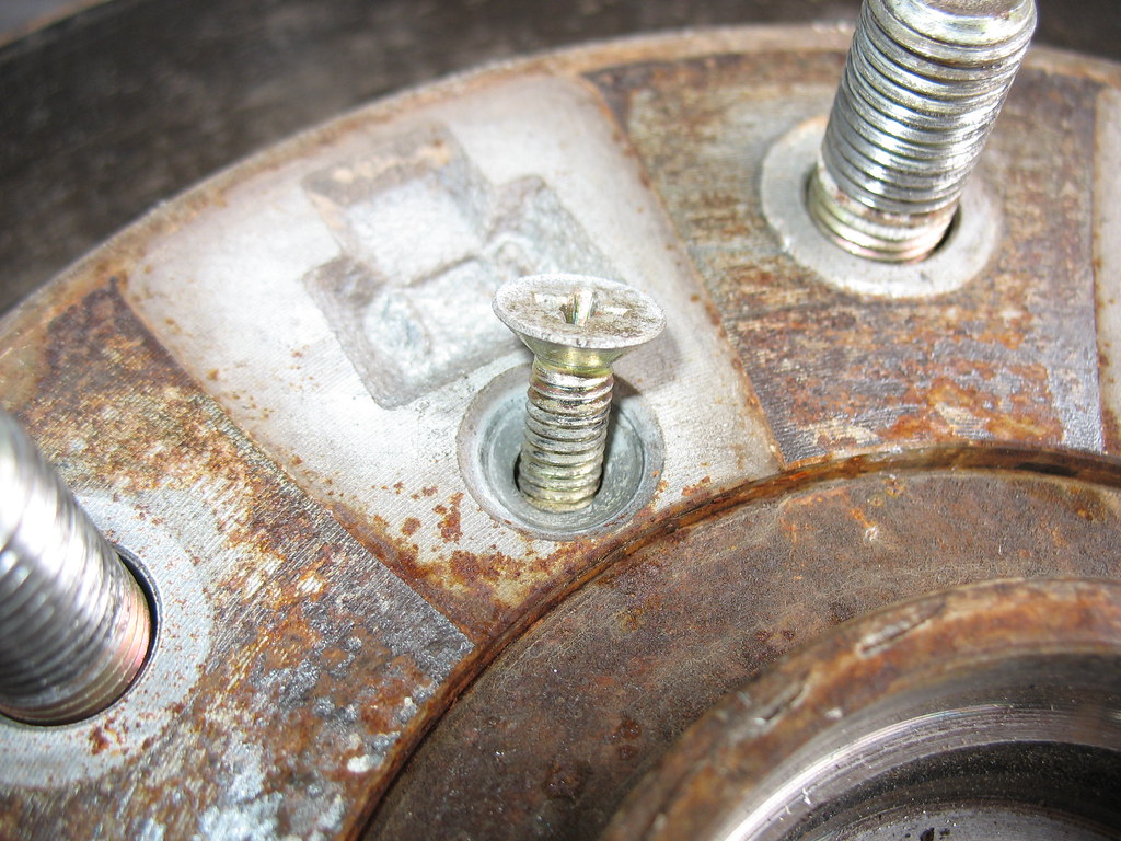
Then find a little bolt that fits into the threaded hole on the rotor as shown here. I'm sorry that I don't remember the size of this bolt. It was in my bolt box. It's metric. Drive it into this hole and it will push the rotor right off the hub.
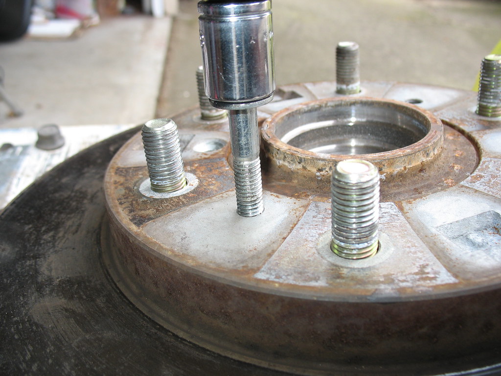
I guess I forgot to show the rotor dust cover being removed. It's a few little bolts. Your second-grader could do it.
OK, set this beast on a couple of two-by-fours (or four-by-twos if you're speaking the Queen's English). Set it up so that it supports the spindle casting but allows the hub to drop as you tap it out. I set it on the cool Workmate bench that SabreWife gave me for Christmas a few years ago. Use your favorite drift punch, dull chisel, old piece of pipe, or whatever else you have handy to tap on. Work slowly and move all around the circumference of the hub as you tap it out of the spindle casting. Don't worry about hurting the bearing. You're throwing this part away, remember?
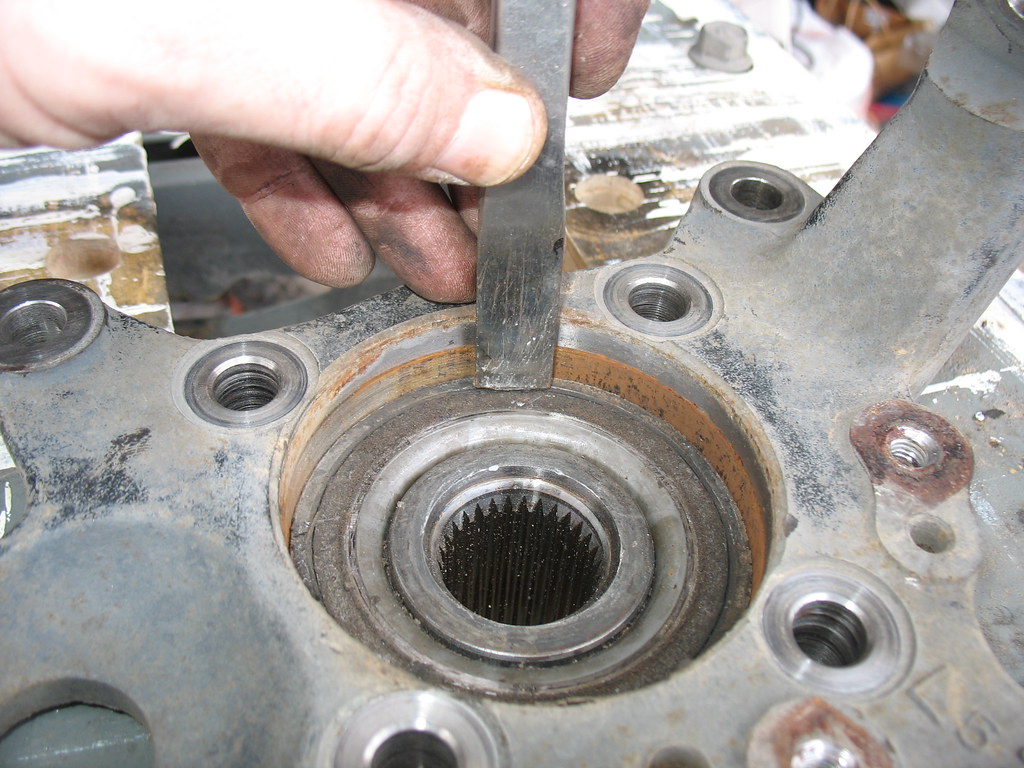
After a few minutes of patient tapping, your hub will drop out of the spindle. Please do not do this job wearing flip-flops. Seriously. You'll break your toe.
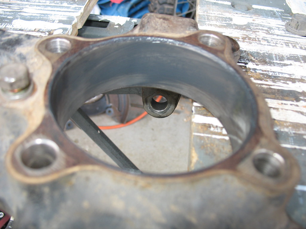
OK, what I did next was to use a little piece of fine sandpaper or emery cloth to just clean up the big hole there in the center of the spindle. Of course it's a bit rusty...you've been fording creeks, haven't you? In the picture above I have already cleaned up the hole and have actually put a fine film of grease in there to ease the new hub into place.
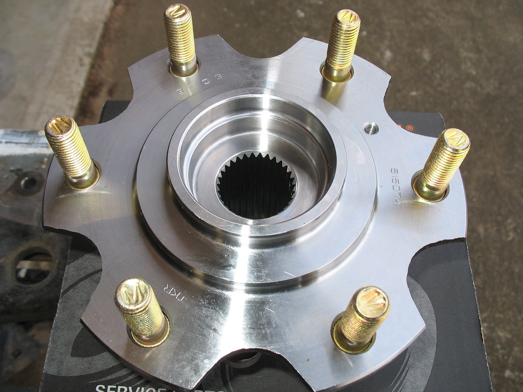
Alright, here's the sexy new part. Note that I have thoughtfully provided the part number in the photograph. Timken is a high-quality producer of OEM bearings for any number of manufacturers and applications. They're not very expensive, either. The cost of this job is all in the labor. I have Scots blood in me, so I'm frugal. See why I'm doing this? Oh, hey, did you know that it was two Scotsmen who first invented copper wire? Yeah, they both had a grip on the same penny.
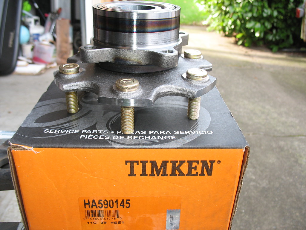
In the above picture you can see that the top of the hub is what will be be fitted into that big hole you just cleaned up in the spindle. Those four threaded holes will be used to bolt the hub and spindle together. The bottom side is where the brake rotor will be, and those are your brand spanking new wheel lugs on the bottom. Pretty, ain't it?
Here's the outer face of the hub before the thing is bolted into the spindle. This is the side where the brake rotor will go. See the little threaded hole where that one tiny screw will secure the rotor?
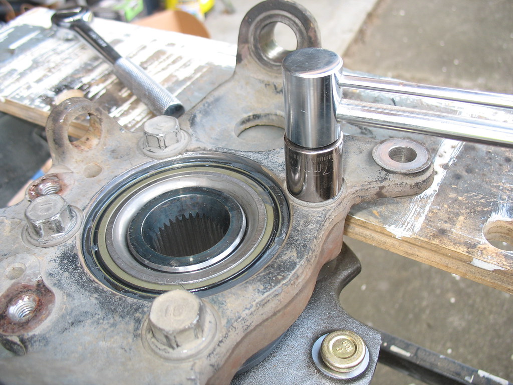
So the cool part is that the hub and spindle just slip together. You don't need a bearing press, you don't need to put one in the freezer and the other in the oven, and you don't need to worry! Just swipe a bit of grease on the two opposing surfaces, and enjoy the silky, greasy feeling of the hub sliding right into the spindle. Bolt it back together. Use your torque wrench: 65 lb-ft or 88 Newton-meters.
Oh yeah, while we're at it, let's talk about torque. Use the proper torque. Recall my previous disclaimer: don't come crying to me if your wheels fall off and you drive off a cliff or rear end a station wagon full of nuns. Here's the official documentation:


So, the hard work is all done. You bolt the spindle and hub together, remembering to replace the rotor dust cover. You heft this beast back in place and replace the lower and upper ball joints (a little fresh grease on the ball joints and axle splines, please). You replace that big, clunky brake caliper. You replace the speed sensor and the little C-shaped metal stamping. You replace the tie rod connection. You replace the axle nut, torque appropriately, and replace the cotter pin. It's a serious matter, so you even spring for a new cotter pin! Oh you big spender you! You replace the dust cap, put your wheel back on, and Bob's your uncle. Don't forget to pump the brakes a few times before venturing out onto busy thoroughfares.
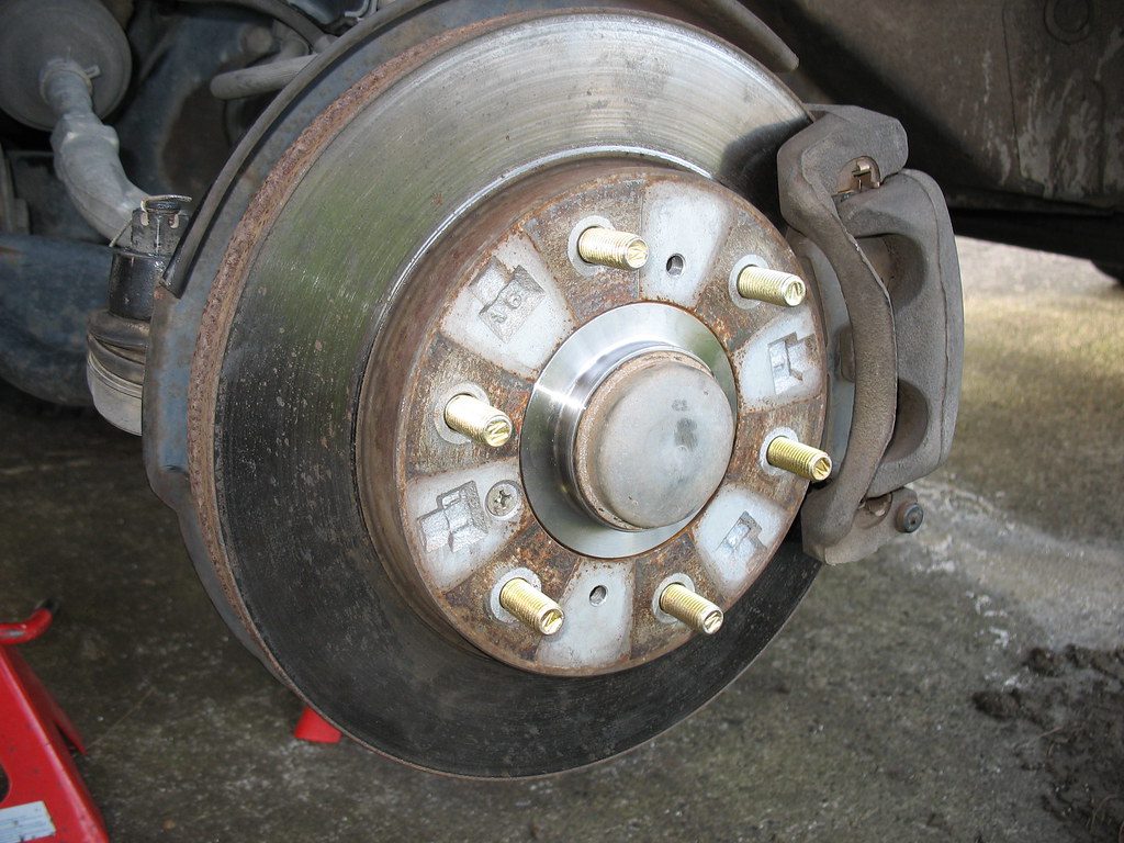
Honestly, I did the left side first and it took me just over an hour. The right side took me 20 minutes flat. This exact job cost me almost $2,000 when the professionals did it on my Volvo XC70 wagon...thus, my motivation to save a few sheckels now and to pass the secret along to you, gentle reader. Cheers.
The first step is to jack up the front. Note that this pic shows the right front being jacked up, although the procedure itself is shown on the left (driver) side. Get it on some really safe, solid jackstands. Don't use a stack of wobbly chunks of lumber, you cheap bugger. Safe enough? OK, now remove the wheel.

Here's what you'll see; again, we're on the LEFT side now.

Use a screwdriver to pry off the dust cap on the end of the axle. Removing the cotter pin and the axle nut is pretty straightforward.


Now, to free the axle itself you tap the end of it with something. DO NOT start bashing away with your favorite hammer! What you want to do is to tap the axle back without buggering those lovely threads. Put a piece of scrap wood over it and then wail away with the old claw hammer. No, seriously...it doesn't take much of a tap and you'll soon see that the axle floats in and out quite nicely.
OK, let's get a picture of the lay of the land. Here's the left, front suspension viewed from the front.

Right there in the middle you can see the axle angling down from the front diff. Remember, we're on jackstands here with the suspension at full droop, so the axle angles down pretty dramatically. Note that the CV joint, hidden beneath the rubber bellows boot thingy, is flexing at a pretty good angle. The reason that these rigs are limited to a suspension lift of 1.5 to 2 inches is because of this CV joint. Exceeding this angle will both tear those boots apart and wear the CV joints prematurely. But it's OK, because these massively competent beasts don't need much lift, anyway. We're overlanders, not mudders or crawlers, right?
OK, you can also see the tie rod end kind of out of focus there in the upper right. This is going to come apart next. You can also see the toothed "sprocket" of the ABS system with the wheel speed sensor visible there looking like a spark plug wire. This sensor will be removed shortly, too. At the very bottom is the lower ball joint; its twin, the upper ball joint, is out of the picture at the top. These both get separated, too. But first, let's look at that tie rod end.
Here's the tie rod after separation. Please note a few details about this.

After removing the cotter pin and retaining nut, this joint is easily separated IF you know the secret. Ladies and gentlemen, one of my primary motivations in posting this thread is to save you the aggravation that I suffered. Let me put your fears to rest and share my new-found knowledge, so that you might have a joyful experience. In other words, do as I say and not as I do!
You DO NOT hammer on the upper, threaded end! Want to know what will happen if you do? You'll bugger those threads! Wanna know how I know this? Want me to teach you some new swear words?
The simple secret is contained in the fact that this is a TAPERED joint. Look closely at the shaft below the threaded area. Note that it's actually a gentle taper. It fits in turn into a slightly tapered hole. To free such tapered spindle joints, you tap on the SIDE of the joint, 90 degrees to the axis of that threaded shaft. Feel free to bang away like a madman, cuz you're not going to break anything hitting the side of that heavy casting. Of course, if you go off course and smash those lovely, delicate threads, you're on your own. Don't say I didn't warn you. What I recommend is to leave that retaining nut loosely in place while hammering the side of the casting. If your aim isn't true, you'll protect the threads by keeping the nut there.
OK, next we'll get that wheel speed sensor out of there. It's held in place by a stamped metal part that is easily removed by backing out a few bolts. Easy-peasy. Since you're not going to unplug anything, just tie the sensor up out of the way with wire, duct tape, or your bubble gum.

Oh, you can see the upper ball joint at the top of this picture, just above the brake hose. Be patient...we'll get to this.
Now we'll remove the brake caliper. You don't need to open up the brake system or do anything at all to the brakes for this procedure. Of course, they always tell you in every set of instructions that I've ever read, "never apply the brakes when the caliper is removed cuz you'll push the pistons out of place and make a horrible mess." So, you know, don't hop in the rig and apply the brakes, m'kay? Oh yeah...the caliper bolts are obviously big and strong. Don't destroy your knuckles when the socket wrench slips...proceed with caution. Really, it's simple.

Once the caliper mounting bolts are out, you'll find that the pads are still gripping the brake rotor (disc) and that the caliper is sort of stuck. It's safe to just push the pads back in a bit, loosening their grip on the rotor. You can do this by putting a little twist or rocking motion on the caliper to slowly shove those pads back against their pistons. Heck, you can even jam a screwdriver in there and pry them back a bit. Oh yeah...this is the part where instruction manuals tell you that you have to remove the top of the master cylinder reservoir and place a piece of clean cloth over the top. You know, because, like, you're going to be pushing massive quantities of brake fluid backwards up the lines into the reservoir. Except that...um, no, you're not, and you can just leave that master cylinder reservoir alone. Of course, if your car breaks it's not my fault. I'm not a licensed mechanic and can't be held responsible for your potentially fatal brake failure. But, you know, it's gonna be fine.
Oh yeah...hang that big, heavy brake caliper up there with a nice bungee cord or something. You don't want it hanging down getting in your way, and you don't want it tugging on that rubber brake hose.

Here's a better look at that wheel speed sensor sprocket with part of the stamped metal bracket moved out of the way (lower left corner of pic):

And this picture shows a good view of where that speed sensor usually lives: in that hole about the diameter of a finger, right next to the threaded hole that is used to hold it in place:

OK, viewed from above, there's the speed sensor lying loose there in the lower left corner. And, FINALLY, there's the upper ball joint. Note that I've done all the hard work for you...it's already had the cotter pin & retaining nut removed and it has already been separated! And you didn't need one of those pickle fork tools or anything else more complicated than a hammer, now that you have been gifted the secret of tapered spindle joint separation. Yeah, it's tougher than the tie rod end. Duh! No worries...just bang away until it suddenly surprises the heck out of you and drops out of the joint. Cuz that's exactly what happens!

OK, ready for the final push? Here goes. Repeat this with the lower ball joint. Same procedure: cotter pin, retaining nut, hammer like a caveman on the side of the casting. Only THIS time, it really will drop right off when it separates, because absolutely nothing is holding it together at this point. Be ready to catch the whole thing. Really, no kidding. Be ready. And it's heavy.

So, this is the massive thing that just fell into your hands. Let's study it.

It's lying there, rotor-side down. The upper casting is called the spindle. You see the lower ball joint fitting on the left, the upper on the right, and the tie rod end fitting extending toward us in this picture. There's that empty hole where the speed sensor was, and those threaded holes where the little metal stamping was removed. The big black round thing under the spindle is the rotor dust cover. At the center of the spindle you can see the inner end of the hub itself. Note the little splines that mate with the axle splines. The Toyota guys are always talking about the number of splines that they have. We Montero guys don't need to count our splines because we have have plenty and they never break.
Here's another view of your truck since you removed this essential bit. Viewed from the rear, you can see how the lower shock (well, it's called a strut in the front) mount looks. You can also see the bump stop...that black rubber dome-shaped thingy...that limits upward travel under extreme spring compression. Some people think that you can remove this and replace it with a low-profile bump stop. These folks think that your articulation will improve. Guess what? It's a Gen III Montero. It has four-wheel independent suspension. It ain't never gonna have spectacular articulation. You've picked the wrong vehicle if you want to win a flex-posing contest. Just go out and drive it up the trail that the Toyota guys struggle on. Spend your money on some good beer to enjoy at the top of the trail. Chuckle to yourself at the $14,000 suspension mods on the JK.

OK, this part is sort of cool. Want to know what's holding your brake rotor (disc) on to your hub? Only this little screw. Unscrew it.

Then find a little bolt that fits into the threaded hole on the rotor as shown here. I'm sorry that I don't remember the size of this bolt. It was in my bolt box. It's metric. Drive it into this hole and it will push the rotor right off the hub.

I guess I forgot to show the rotor dust cover being removed. It's a few little bolts. Your second-grader could do it.
OK, set this beast on a couple of two-by-fours (or four-by-twos if you're speaking the Queen's English). Set it up so that it supports the spindle casting but allows the hub to drop as you tap it out. I set it on the cool Workmate bench that SabreWife gave me for Christmas a few years ago. Use your favorite drift punch, dull chisel, old piece of pipe, or whatever else you have handy to tap on. Work slowly and move all around the circumference of the hub as you tap it out of the spindle casting. Don't worry about hurting the bearing. You're throwing this part away, remember?

After a few minutes of patient tapping, your hub will drop out of the spindle. Please do not do this job wearing flip-flops. Seriously. You'll break your toe.

OK, what I did next was to use a little piece of fine sandpaper or emery cloth to just clean up the big hole there in the center of the spindle. Of course it's a bit rusty...you've been fording creeks, haven't you? In the picture above I have already cleaned up the hole and have actually put a fine film of grease in there to ease the new hub into place.
Alright, here's the sexy new part. Note that I have thoughtfully provided the part number in the photograph. Timken is a high-quality producer of OEM bearings for any number of manufacturers and applications. They're not very expensive, either. The cost of this job is all in the labor. I have Scots blood in me, so I'm frugal. See why I'm doing this? Oh, hey, did you know that it was two Scotsmen who first invented copper wire? Yeah, they both had a grip on the same penny.

In the above picture you can see that the top of the hub is what will be be fitted into that big hole you just cleaned up in the spindle. Those four threaded holes will be used to bolt the hub and spindle together. The bottom side is where the brake rotor will be, and those are your brand spanking new wheel lugs on the bottom. Pretty, ain't it?
Here's the outer face of the hub before the thing is bolted into the spindle. This is the side where the brake rotor will go. See the little threaded hole where that one tiny screw will secure the rotor?

So the cool part is that the hub and spindle just slip together. You don't need a bearing press, you don't need to put one in the freezer and the other in the oven, and you don't need to worry! Just swipe a bit of grease on the two opposing surfaces, and enjoy the silky, greasy feeling of the hub sliding right into the spindle. Bolt it back together. Use your torque wrench: 65 lb-ft or 88 Newton-meters.

Oh yeah, while we're at it, let's talk about torque. Use the proper torque. Recall my previous disclaimer: don't come crying to me if your wheels fall off and you drive off a cliff or rear end a station wagon full of nuns. Here's the official documentation:


So, the hard work is all done. You bolt the spindle and hub together, remembering to replace the rotor dust cover. You heft this beast back in place and replace the lower and upper ball joints (a little fresh grease on the ball joints and axle splines, please). You replace that big, clunky brake caliper. You replace the speed sensor and the little C-shaped metal stamping. You replace the tie rod connection. You replace the axle nut, torque appropriately, and replace the cotter pin. It's a serious matter, so you even spring for a new cotter pin! Oh you big spender you! You replace the dust cap, put your wheel back on, and Bob's your uncle. Don't forget to pump the brakes a few times before venturing out onto busy thoroughfares.

Honestly, I did the left side first and it took me just over an hour. The right side took me 20 minutes flat. This exact job cost me almost $2,000 when the professionals did it on my Volvo XC70 wagon...thus, my motivation to save a few sheckels now and to pass the secret along to you, gentle reader. Cheers.
Last edited:
