How does stuff like this take SO long....
I was finally able to come up with a shifting system for the transfer case! Finally!
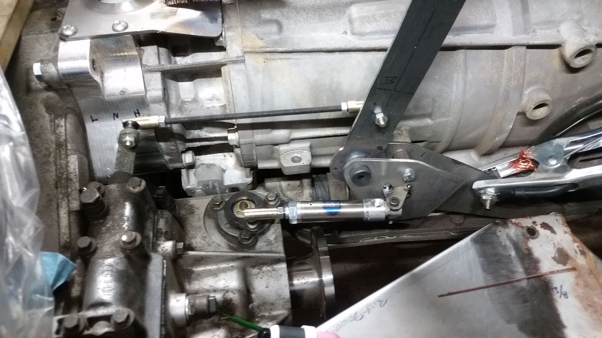
The high-low selection is done by a lever system. I was able to grab a 3 bolt mounting pattern off the side of the 6L80E transmission in about the right locaiton. The pivot for the lever is a small machined section of 1"dia x 3/16" wall tubing that has permanently oiled flanged bushings pressed in. That pivot tube rides on a 1/2" shoulder bolt with a lock-nut to provide tension adjustment as the bushings wear. The pivot is also in double shear with an add on bracket that will be braced to the main bracket when I pull it apart for final welding. The relay rod uses rubber shielded ball joint pivots on both ends. I will be augmenting/replacing the threaded rod with something a little stiffer on final assembly. There is a little bit of bow in the rod when things are bound up and you are really pulling on the lever. I'm not totally happy with the shift lever yet. I will probably add a jog bend to it to bring it in closer to the centerline of the chassis to save a little leg room for the passenger. There may very well be a version two or three of that lever as I get the tunnel built out.
I decided to use a small air ram to actuate the center diff lock on the transfer case. I have some rough plans to convert the toyota e-lockers to air actuated also. I used an off the shelf Bimba cylinder from McMaster. These are very affordable at maybe $35 in this size. On the transfer case side the cylinder uses another rubber shielded ball joint pivot. That little pivot attaches to a pivot lever which is welded to the key plate that I made. I mapped out the leverage ratio and arm length so that I could use a standard cylinder length without needing any kind of stop of either end. Fully extended is the lock position, fully retracted is unlocked. The pivot lever was a very tight fit. The pivot location is actually right on top of another fastener on the transfer case. I decided in the end to make the pivot lever out of material thick enough to tap to 1/4-28 for the ball joint stem. The tail end of the cylinder has a small brass bushing for a 1/4" pin. I was able to make a few small brackets to connect that to the shifter brackets.
The only thing that didn't work like I wanted in the end was the spring return. The spring in the cylinder is just not strong enough to pop the lever to the open position reliably. I am going to add a secondary return spring I think to help the spring in the cylinder. Then it is just a matter of finding a spring strong enough in the size I need that will fit in the space I have....
I'm sure I will find something...
Some shop/fab tips from this part of the project.
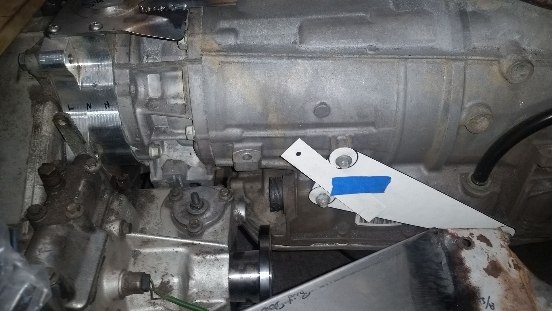
Don't worry about making the first template in one piece. It was much easier in this case to add the pivot location after the main bracket template was already done. Then I just make another template for the final bracket shape one I had ALL the hole locations.
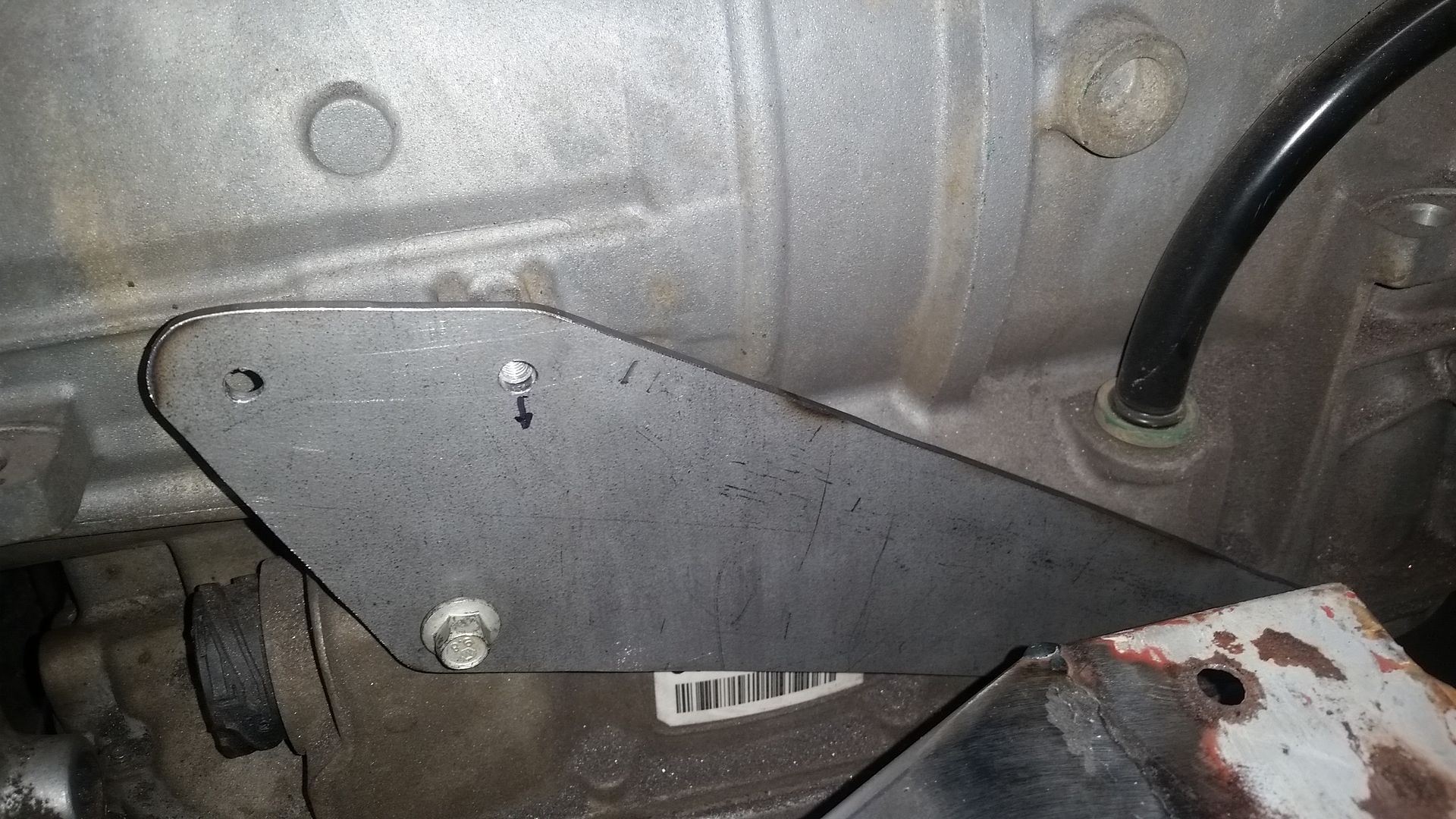
If you have a hole that doesn't line up perfectly, take an extra second to mark the direction that the hole needs to be adjusted. This way once you remove the bracket you know how it was bolted on and where you need to file to adjust things.
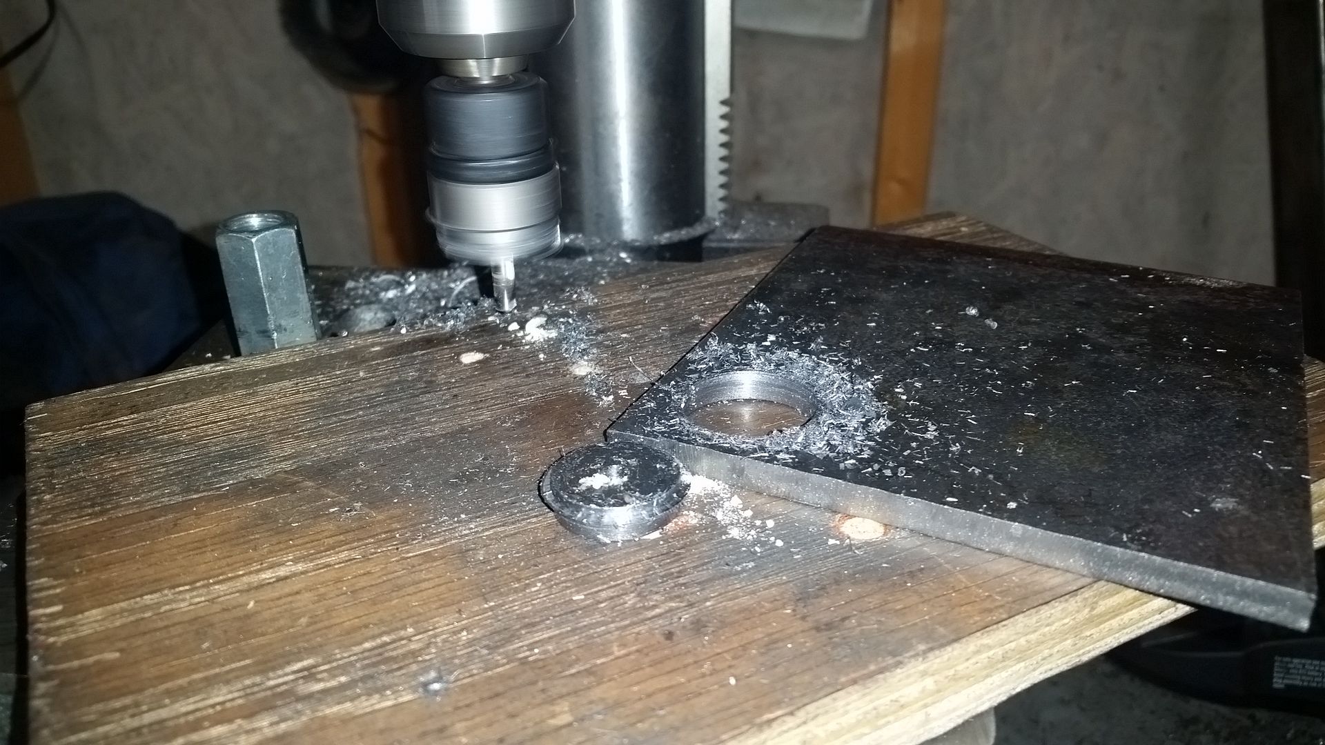
Blair Holcutters are great, but they have thickness limitations. If you cut from both sides you can really stretch them out. The center pilot reaches all the way though so it is very easy to just flip the part over. Cutting from both sides seems to work better in a lot of ways on thickness.
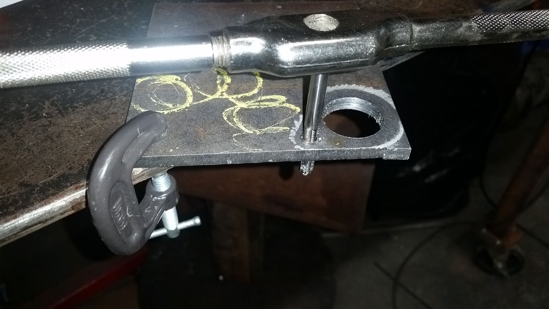
If you have to tap a hole in a smaller part, tap it before you cut it out. It is way easier to keep things straight and level.
Also, silver sharpie works great for making the edges on metal in some cases. It is much easier to see than black for my eyes in some cases. In this case I just used a paper template and 'wiped' the edge of the sharpie off the template instead of trying to trace around it. This gives you a finer line in a lot of cases for more detail cutting. You basically cut/sand/file off all the silver to get the exact shape.
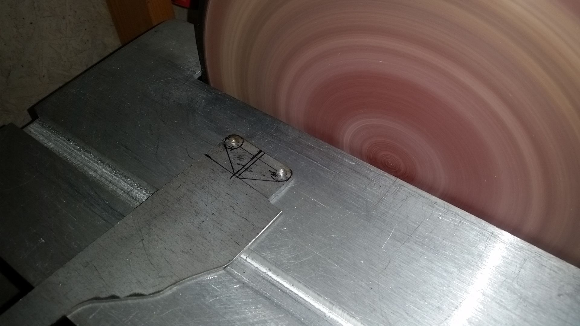
Sometimes it is easier to try and clean up most of a small part before you cut it out of the plate. A little forethought goes a long ways with small parts like this.
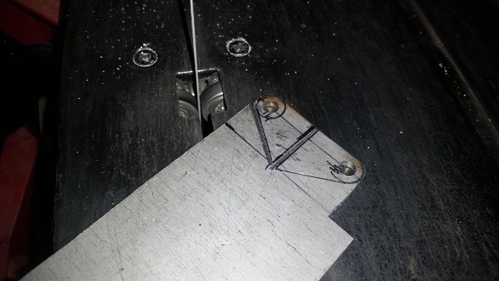
It is also easier/safer sometimes to cut small parts out one as a time vs in pairs. Again, just trying to think ahead helps.
")


