Blender, My LX450/FZJ80 + FJ45esk + GM + Land Rover crazy concoction

Metcalf

Expedition Leader
I have started a new project that is going to be a pseudo replacement for my 1942 Willys MB and my Dodge W250 that I built a few years back.
You can read about those builds here....

http://www.expeditionportal.com/forum/threads/58343-Rango-1942-Willys-MB

And.

http://www.expeditionportal.com/forum/threads/24653-Project-Doitall-Dodge

I am going to have to play a bit of catch up with this thread. I don't get over the Expo as much as I would like these days. I got sucked into the Willys section at Pirate4x4 when I was building my 1942 MB. That little thing opened a few doors for me. After taking it on a few trips to Moab and an epic 2000+ mile 13 day trip up north...

Read about that here....
http://www.pirate4x4.com/forum/jeep-willys/1280122-2000-miles-nervous-nirvana.html

...I was lucky enough to be one of the readers invited to attend the 2014 Ultimate Adventure trip hosted by 4-wheel and Off-road Magazine. That trip consisted of a crazy 3150 mile tour of the midwest. In 2015 I was invited back to Ultimate Adventure again as the Returning Reader. Once returning from that trip the gears in my head wouldn't stop grinding away at what to build next. I had another project lined up to build that was ( and still is ) a frustration. In a fit, I made the mistake of cruising Craigslist for a project. I knew generally what I was looking to build as far as the general package, but I didn't know what to start with.

After my adventures over the last few years, my wishlist has evolved as I spend more time neck deep in this sport. My Dodge has been a great vehicle for years. It is basically just a 1 ton diesel powered 4wd truck with big dumb tires. For a lot of things it works well. It has a top, doors, windows, heater, power, and gets good mileage. My ol' Willys, on the other hand, is open, small, short, limited to about 60mph, and did I mention small. While I love the little thing to death, and it is FAR more capable than I ever through a vehicle on 35" tires and an 85" wheelbase could be, it just isn't that practical.

What I really wanted was a blend ( ha...get it...blender ) of both those vehicles.

This is what I came up with so far....


-1996 LX450 ( same as FZJ80 ) chassis ( it was a super clean unit with only 110K miles that was flopped over in a ditch on a snowy road )
-1970 FJ45-esk custom pinched cab/tub ( which started out as a mostly rust free FJ40 tub from Arizona )
-2013 LC9 5.3 GM V8 all aluminum engine ( from a rolled truck with less than 50K miles )
-6L80E 6-speed automatic ( from the same truck as the engine and still attached from the factory )
-Land Rover LT230 transfer case ( from a Discovery2(?), it is the SE version with the unused center diff lock from the factory with 1.2 high range and 3.32 low range.
-Toyota Factory 4.10 E-Locker Differentials ( that came in the LX450 from the factory )
-40" Tires and Beadlock wheels ( because I like big dumb tires )
-Warn 8274 winch

In general I wanted ( no real specific order )

-About a 110" wheelbase, the J80 chassis is 112" (close enough)
-Modern, reliable V8 power with about 300hp, cheap, with easy to find parts.
-Automatic transmission. I think for the technical 'wheeling they do have an advantage.
-BROAD gearing, not just low gearing. I like being able to run between harder section of the trail, and in the sand/desert, without having to do the low-hi range shuffle.
-Be able to travel at modern interstate speeds of 75-80mph without needing a death grip on the wheel and focused concentration.
-Cruise control. I seem to always go on these long adventures....
-Flat smooth belly at about 1/2 tire diameter. I tend to build vehicles very low for stability and handling. To make that work I try and maximize the belly clearance while keeping it as smooth as practical.
-Limited front overhang. Just enough room for the winch past the grill. It won't be a 90 degree approach angle, but close
-Limited rear overhang. With the longer wheelbase you can more easily get the front end up on very large obstacles. If the rear end gets in the way your forward/upward progress stops
-25-30 gallon fuel capacity that doesn't get in the way
-Full float rear axle because semi-float shafts suck when they break, or bend, when you're doing stupid stuff you shouldn't (check)
-Serviceable wheel bearings, because I like being able to inspect/replace/repack those parts (check)
-Big dumb tires, because I feel that allows me to do crazy things that I like to do.
-Room for a big dumb spare tire that will not get in the way of rearward visibility
-4 wheel disc brakes, to help stop the big dumb tires.
-Coil/link suspension, to help with approach and departure angles along with provide a more complaint 'modern' ride quality.
-Front end weight bias, so that when it is loaded down for larger trips it is still close or better than 50/50 front to rear.
-Smaller body. I want the body to be comfortable for 2 people, but no bigger than needed for tight trail work.
-Almost no lift. I like running big dumb tires, but I don't like using feet of 'lift' to do it.
-Modular lockable hard top. While I enjoy an open air high visibility driving immersion in the environment, I hate getting hit in the back of the ear by tire spray on the highway.
-Doors, that lock, with windows
-Heater
-Good ventilation, but no complex heavy complicated A/C systems
-Comfy interior
-etc
-etc

I have a thread in the wrong section of pirate here...

http://www.pirate4x4.com/forum/jeep-willys/2126506-jumping-ship.html

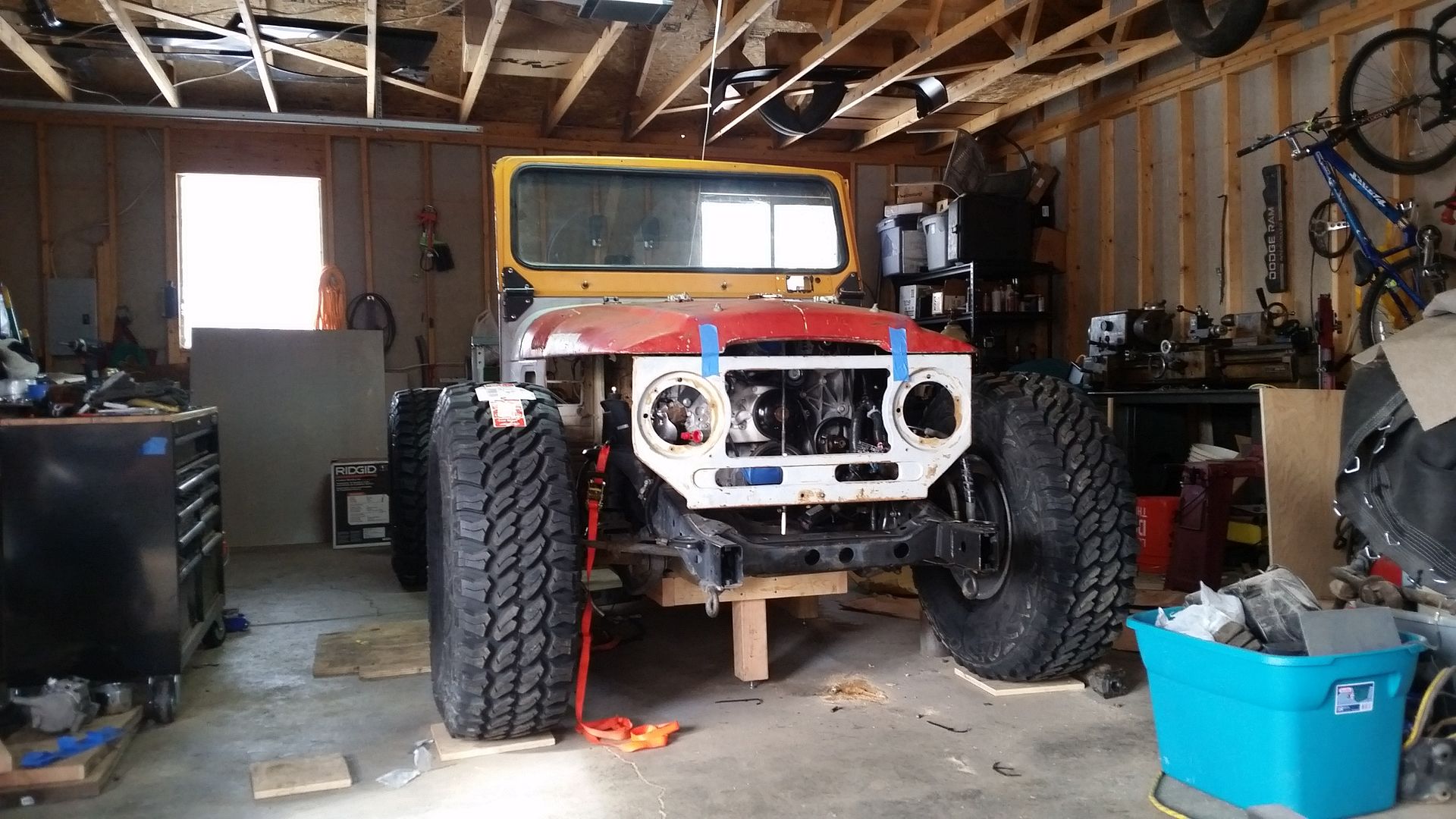
I will be taking off from the point in the above picture in this thread. If you want to ask questions from the stuff in that other thread feel free.
I like questions. I like hearing other points of view and criticism on my dumb ideas.
And go....
 
Last edited:

Metcalf

Expedition Leader
I'm new"ish" to wheeling, etc but my god, I didn't even know 40" tires were a thing. :Wow1:

I will be the 1st to admit that I am on the fringe with tire size.
My old flat fender Willys runs 35s and my Dodge is running 38.5s, both with basically no lift.
 

TrucMan

Adventurer
This is great! Exactly what I would love to build someday, I love your Jeep! So this should be like that only better...


Sent from my iPhone using paper airplanes.
 

Metcalf

Expedition Leader
Damn! There goes what little is left of my spare time! Did you have to???

You've been thinking on this a while. Good to see its on!

Sorry....

This project just kinda happened. I had my heart set on doing something else that I have been designing for a few years, but I just couldn't get it to go like I wanted. In a fit of frustration and with a fistful of cash I ended up here.
 

Klierslc

Explorer
You might rethink the factory locked axles. The rears tend to twist the splines when they break (usually wheeling hard with 37" or bigger tires). This prevents you from removing the broken axle shaft and requires you to cut the housing open to cut out the shafts. The process usually trashes the locker shift fork as well. You may have a lower risk of this being a bit lighter, but the 40" tires are pretty extreme for those shafts. An easy solution might be to trade somebody for a non locked rear....
 

Attachments

  • AXLE.jpg
    AXLE.jpg
    42.8 KB · Views: 289
  • 144_4436.jpg
    144_4436.jpg
    353.9 KB · Views: 288
  • 144_4427.jpg
    144_4427.jpg
    463.9 KB · Views: 307

njtacoma

Explorer
Glad to see this project over here. I don't get over to Pirate.

I have really enjoyed your other builds, so look forward to this one.
 

Metcalf

Expedition Leader
To summarize what I have done with the body so far.


I brought this up from Arizona. It is in decent condition for a 45 year old tub, but not perfect.


Then this happened! I swear it just fell in half like that....


Then I removed what was left of the old toolbox under the drivers seat along with the fuel tank sump. The rear floor support had to go also.


Then I took a 6-7 degree wedge out of the floor pan starting at the door opening and stuck things back together.


Now I am left with a tub that is only about 55.5-56" wide overall. It is just about 3" narrower than your typical CJ5-7-8/YJ/TJ tub. I can still use a stock hood, windshield, wipers, etc. I wanted something slightly less wide in the hips for this chassis. The axles only 63" wide and even with 9" wide wheels with 3.75" backspacing and a 13.5 wide tire the overall width is JUST under 80" wide. Having the body be slightly narrower will keep it out of trouble on the trail.

This body is also 'modular' for the most part. The windshield frame comes off, the top panels bolt on, etc. This way, it if is damaged on the trail I can replace parts without having to worry about the entire tub that much.

I went back and forth ( and honestly still am ) about building a pickup vs an SUV shape. I think both have upsides and downsides.....


I have decided to make this one a small pickup. It will be stretched about 2.5-3" from a standard Toyota FJ45 dimensions. The back end is basically going to be a simple skin over a 1.5" square tube skeleton that will also function as the rollcage. With the smaller cabin volume I didn't want to sacrifice a lot of space by having a separate cage structure. The top panels will also be bolting to this structure, in the end I think it will actually save be a decent amount of work along with space.

The hood will remain stock for easy replacement. I got this cool extra patina mockup hood from the guy selling the tub. It is pretty rough, it will work for mockup and test driving but I am in search for a later model seamless hood in good condition for when it goes to paint.


While the hood can remain stock, I am going to have to do quite a bit of work to the grill to make room for the tires to turn. This is a rough 'chop of what the modded grill will look like. I am basically going to have to move the headlights in about 2" per side to give me enough room to eliminate the 'corner' on the factory grill shape. I will narrow the bezel also....which I need to find also.

The front end will be getting some small aluminum sheet fenders to help blend with what I am going to do on the bed I am designing.


I also have to cut a big freaking hole in the floor to make room for the transfer case. The Land Rover LT230 is NOT a mall unit. The entire powertrain is above the bottom of the frame rail to provide a completely flat belly. The body is as low as practical on the chassis. There is only about 1" of clearance over the engine to the hood ridge.

In the end it doesn't look like the vehicle will be as low as I hoped for. While the suspension will be 'stock', the position of the body is adding about 2" of 'lift' compared to a stock FJ40 from what I can tell. The J80 frame is 6" tall in the belly section and the FJ40 hat channels are rather chunky units. The body can't really go any lower unless I swapped to a car intake on the engine, which I don't want to do. Having about 2-3" of 'lift' overall to run a 40" tire doesn't sound too bad. My math may be a bit off also compared to 'stock'. The chassis will think and drive like it doesn't have any lift other than what I get from the reduction in sprung weight. My hope is that this vehicle will just squeak in under 4000lbs when it's done. It will be close, and likely over that with a full tank of fuel, people, a 40" spare tire, etc.

Ok.....I think that is where I am at with the body.....
 

Metcalf

Expedition Leader
You might rethink the factory locked axles. The rears tend to twist the splines when they break (usually wheeling hard with 37" or bigger tires). This prevents you from removing the broken axle shaft and requires you to cut the housing open to cut out the shafts. The process usually trashes the locker shift fork as well. You may have a lower risk of this being a bit lighter, but the 40" tires are pretty extreme for those shafts. An easy solution might be to trade somebody for a non locked rear....

How about adding alloy shafts? From my research, that seems to fix the spline twisting and breaking issue for the most part.

http://www.justdifferentials.com/AXTFF-FJ80-p/axtff-fj80.htm

or

http://www.rdmoffroad.com/polyperformance-toyotafj60andfj80full-floatrearaxleshaftspair.aspx

The other think I have been looking into is seeing how similar the E-locker internals are from a later model cruiser with 32 spline shafts. I have heard rumors that it may be possible to swap some of the parts around to allow a 32 spline shaft to fit. That may only apply to other differentials and not the factory e-locker.

Buying a non-locked axle, and then another locker, isn't in the cards....or rather the wallet.

I should be seeing a fairly drastic weight loss from the stock application, especially a build stock bodied vehicle. Most of those I have found seem to be pushing 5-6K pounds loaded, with a LOT of weight on the rear axle. This thing is going to be as light as practical on the rear axle. The fuel tank will be located behind the axle, but the bed will be mostly aluminum. I tend to pack pretty light. I will likely run a full size spare TIRE ( only the tire ) on longer trips. I will make sure to get some corner weights when it's getting close to done.

I watched one of the other UA2015 invited readers BEAT on his FJ80 rear axle with E-locker which had upgraded shafts. He was running 38.5 sticky tires. This was swapped in a 4-door sidekick, but it was loaded down pretty good for this trip. That gave me some faith in the alloy shaft solution....

Thank you for the input.
 

Metcalf

Expedition Leader
Last night was arts and crafts!

I started off in the computer however.


I use solidoworks for most of my designing in the box mainly. I am lucky enough to have collected a fair number of files over the years from here and there to work with.

Once I have a design in solidworks I like, I can print a 1:1 paper template. Then I spray glue that template to whatever material I want to cut the template out of. In this case I am just doing a trail fit of the parts in the chassis since I do not have a model of that.


I made a foam board model of the engine mounts I designed. Foam board is cheap and easy to work with. It has enough rigidity that it retains its shape. You can make taps and slots to hold assemblies together just like you can with cnc materials. A little hot glue holds it all together. The hardest thing to do is cut holes. That takes a little time to do cleanly.

These mounts will be using a large Johnny-Joint type joint. My hope is that these joints will allow some misalignment when installing/removing the engine, but some compliance with the urethane bushings to isolate some vibration. The mounts will also be a 'captured' design where if the bushing was to fail, the engine would still be mostly constrained.


I decided to use the new weld-on kit from Trail Gear. There are about a dozen or more companies making this style joint now. Trail-Gears version looks just as good as any I have seen. The joint had proper preload on the bushing. The snap ring groove is nice and deep. There is a grease port not only in the shell, but also in the ball. The surface finishes are all good quality.

They are selling for $20 shipped!

https://www.trail-gear.com/TG/Creeper_Joint_Kit__Weld_On__18mm/i_0_0_4471/_303892-KIT.aspx

You might have to look around for a free shipping deal.

I elected to design the bushing into the removable part of the mount, not on the frame. This should make fabrication of the mount easier, along with repairs in the future. I am using a standard 2.63" wide bushing also. This gives me the option to rebuild the bolt on mounts with a multitude of other bushings if the vibrations are too extreme with this style of bushing.


Drivers side test fit.


Passenger side test fit.

Overall everything looked pretty good. I am debating a little bit on using a common part on the engine or making an A and B side. The engine is offset in the chassis 1" to help with the front driveshaft clearance. If the part on the engine is identical the distance to the frame rail, and corresponding leverage, is different.

I am probably going to make the passenger mount slightly longer and lower both mounting points 1/2". The lowered position will give a little more clearance to the exhaust manifold which will be a significant heat source. I should also think about adding some kind of heat shield on the mount itself to further isolate it from the exhaust heat.

Off to make V1.1 of the engine mounts....
 
Last edited:

Metcalf

Expedition Leader
Body to Frame and engine setting catchup...

I figured I would do another summary of where I am at with the body/chassis/powertrain juggling.....


After pulling the spring and rubber bumpstops out of the chassis, I basically stared by leveling the it the best I could on my not-level concrete garage floor. The body was then roughly positioned on the frame. The only 'known' reference point I really had was that I wanted the grill to sit JUST in front of the steering box. From a few other builds on Pirate and some pictures I found of other FJ40 on J80 chassis builds I found, that looked like a good place to start. Staring with that known reference, and that I knew I wanted the body centered side to side on the frame, this gave me a 'home' position to use. I still didn't know where the body was going to end up vertically because I didn't have the powertrain at this point. I decided to make a set of very temporary body mounts so I didn't have to spend hours measuring every time I had to remove the body from the frame.....


This is what I came up with. It is just some 3/4 box tube and hardware scabbed together. I turned up a small bushing that fits in the old body mount hole. This is just a female receptacle for the 1/2" all thread. Nothing is jointed together. You can still lift the body off the pin. That pin is threaded so that I can adjust the height of the body vertically over the powertrain after it is in position. There is a locking nut that keeps the 'home' position set vertically one I find out where it is. There is also a welded nut on the very bottom which I use for turning the all thread. You can use an impact driver for fast adjustments, ratchet, or a end wrench.


In order to give myself a reference plane for the powertrain, I decided to build a quick wooden table that would fit under the frame rails in the belly section and extend forward towards the front axle. One of the goals for this build was to have the belly of the chassis be flat to the frame. When setting the powertrain I HATE having things floating around in space hanging off of a hoist. With the clearances I usually built to with my typical low slung vehicles it just isn't practical to set the engine that way. This table will allow me to set the entire mess on top without having to have anything connected to the engine hoist. I can set the angle and position just like I want with cribbing under the oil pans. This also gives me a very good reference plane for how much clearance things will have to the belly pan when I am finished.


Somewhere shortly after building the table top my new tires showed up. When your building a car with basically no lift and a 40" tire you start to doubt if they will fit sometimes. I decided to mount the tires up and install them on the chassis to see how much space they really took up. I had measured at least a dozen times to see if they 'should' fit with the body position I had basically pulled out of my rear end.

Before I got my engine and transmission I had already started measuring the position of the body to frame and where the engine might end up. One 'wishlist' item that came up a few years back, and again on both Ultimate Adventure trips, was how nice it would be if the vehicle used the same length driveshaft front to rear. That way you only need one spare part and it would fit either end. In a worst case situation, you could pull the front driveline and install it in the rear to get you home in rear wheel drive. After lots of head scratching, graph paper, measuring, and thinking....it looked very possible in this chassis/body combination.

Using all my rough calculations, I basically guessed that the body needed to go back 1" more than my initial guesstimate based on the pictures I had seen of builds like this. Originally I had about 1.75-1.88" of clearance between the grill face and the factory J80 steering box. I decided to move the body back that extra 1" before fitting the tires and wheels.


I ended up making this horrible looking little jig to add a position for the temporary body mounts that was 1" further rearward. Then I simply moved the all-thread back to the new position and set the body back on the pins.


At this point I decided to actually bolt the tires/wheels onto the axles. This raised the position of the frame/body and it was no longer level, but it did allow me to do a quick check fit for clearance with the very much larger tires with the front of the tub. All went WAY better than I could have hopped. The turned tire cleared the tub with plenty of room for articulation. The chassis is sitting metal to metal right now. There is VERY little chance that the suspension will ever get this compressed again, but a little extra space is good insurance as the suspension is will remain using all the stock rubber mounting bushings. I have been pretty impressed with the tight, but realistic, clearances that the Toyota J80 chassis was built to as far as the suspension. Everything clears lock to lock even with the stock rubber bumpstops removed completely.


As an icing on the cake bonus, the 40" tires even clear the radius arms at full lock with a little extra to spare. This is with a 9" wide wheel that has 3.75" backspacing. The steering stops are still set at the factory length. I have a little extra clearance to play with even! I may have to play with adding a little more steering angle if the steering box and birfield joints in the axle will take it. I am VERY happy to have the full stock steering angle available with a 40" tall tire at this point!


Next it's time to stuff a lot of engine, transmission, and transfer case in the chassis....
 

Metcalf

Expedition Leader
Engine, Transmission, and Transfer Case positioning....

Now it is time to go over the process and the issues I had when setting the powertain position.


This picture basically sums up 90% of the complications I had with the position of the powertrain in the chassis. This picture is looking through the hole for the front output in my mockup Land Rover LT230 case. I had previously set the engine in the chassis, but it wasn't until I received my transfer case adapter that I had a way to fully visualize this issue.

The J80 chassis is very well designed. Both differentials are still traditionally on the passenger side of the chassis. While I was dreaming up this crazy concoction of parts I stumbled upon the idea of using a Land Rover LT230 transfer case. I didn't have any of the stock J80 powertrain parts. The gentleman I purchased the chassis from had removed them to use in a high mile FZJ80, after all they only had 110K miles on them. That is hardly broke in for a Toyota engine! With both axles being offset to the passenger side that limited my transfer case options somewhat. I didn't really see any advantage to using a Toyota transfer case really. They don't seem to be anything special, and the gearing is on the pathetic side. I would definitely have to change the gearing in the axles also for the larger spare tires. That is where the LT230 really started to shine.

The LT230, in most versions, does not have a direct 1:1 high range. It uses a 3rd gear on the intermediate shaft to allow various under-drive ratios to be used. My version of the LT230 has a 1.21:1 high range ratio. If you combine that under-drive high range ratio with the stock 4.10 axle gears in the factory J80 axles you end up with 4.96:1 effective combined gearing. The low range ratio in the LT230 is also lower than most transfer cases you commonly see in the USA expect the Rubicon edition wranglers. All versions of the OEM LT230 have a 3.32:1 low range, while the high range can be 1.0, 1.2, 1.4, or 1.6. With the broad gearing provided by the 6L80E transmission I am using all the math worked out really well.


While the LT230 itself is actually very easy and cheap in the USA for the most part, finding an adapter to mate the LT230 to the 6L80E transmission was another story. I looked at a few one off conversions, and contemplated building my own, before finding a source in the USA. Nicholas Markiw at Rover-Works ( info@rover-works.com ) has taken to swapping Gen 4 LS engines with 6L80E transmission in land rovers. Lucky for me, he offered the adapter I needed for sale that he developed. His adapter is a 2.36" long unit that bolts to a factory GM 4wd 6L80E tailhousing and provides a stub shaft to adapt from the 32 spline GM output to the Land Rover input shaft which rides on a large sealed bearing in a sealed 'dry' adapter.


Once I had identified the issue with the front driveline with the mockup case, it was time to bolt in a full unit. These LT230 transfer cases are NOT small nor light units! Land Rover typically runs their powertrains very close to level with a large amount of clocking on the transfer case. Overall it fit very well in the chassis for the most part. The driveshaft is pretty close to pan. It is still light years better than what you typically see with passenger drop differentials and most of the older GM automatics with larger offset pans.

As a small note, I also eliminated the factory drum e-brake off the back of the LT230. The J80 chassis has an e-brake provided on the axles inside the rear disc brakes.

I also converted the transfer case over to a Toyota pattern driveshaft output flange. The LT230 just happens to have the exact same output spline size and cut as a Ford 9" pinion shaft. Trail-Gear offers a Ford 9" to Toyota flange. I was able to slightly modify that flange to fit on the LT230 transfer case. Any ford 9" pinion yoke could be modified to work I think. The seal for the new flange has been the hardest part. More on that later.

Once I had the full transfer case installed I was also able to check and see how close the front and rear driveshafts where for length. I actually got that to work out! Both shafts are within 1/4" of each other with the suspension fully compressed! Now I should only need one spare shaft and it will fit either end. Win. I love small details like that.

I did run into some issues with the front driveshaft however as illustrated in the 1st picture.


Once I had everything together and setting on the engine table, I was able to grab a section of tubing ans start to better visualize how the front driveshaft might fit.

The J80 chassis has a high pinion front differential. While this provides some protection and a reduced operation angle for the full-time driving front drive-shaft, it does make for some packaging headaches. Since 1st introduced, the GM V8 engines have had a passenger side starter. While the modern LS generation 4 starter is comically small and light compared to the 20lb beasts of years past, it does still get in the way. It isn't so much the starter itself, but the bulge on the bellhousing which provides clearance for the nose of the starter.


Here you can see the offending 'bulge' for the starter nose, and the added kick in the goal post of an added boss on the 6L80E LS V8 bellhousing. This little bugger was right in the way. I was really stoked that the driveshafts where going to be equal length. I didn't want to have to run a reduced diameter front unit to get the clearance that I needed. I really want to be able to use a standard 2" diameter tubing driveshaft if possible.

After playing around with the engine position a bit, I was getting close. I dropped the transfer case down about as much as I could, which wasn't more than about 1/2" because of the clocking angle. I also ended up shifting the engine over to a full 1" off centerline. That helped a bit, but didn't get me all the way there....


I finally ended up having to break out the cut off wheel and the flap disc to remove that offending boss on the side of the bellhousing. I was able to keep the 'hoop' of the bellhousing intact. I also ended up being able to trim down the factory dirt shield and re-install it with the starter. The bellhousing is still as sealed up as it was from the factory.


This FINALLY gave me enough room for a standard 2" diameter front driveshaft at full metal to metal suspension contact. It is close, that is for sure. I highly doubt if the front suspension will ever get this compressed again, but having a little extra clearance built in is probably a good thing.

Now I think we are all caught up. The engine is in the final position and now I am working on building the mounting system for the engine and transfer case. I stuck the body back on again and trimmed the floor out for what seems like a HUGE transfer case. It was a big hole. The firewall ended up having to be trimmed slightly to provide transmission clearance, but I was able to retain the stock dipstick for the transmission! With the engine 1" offset from center the steering shaft looks like it will still clear with no issue. Since the engine is so high in the chassis, and with the body as low over the intake as possible, I think I am going to have to get a little creative with the brake booster and master cylinder mounting. I have a somewhat unconventional idea brewing for that. I kept the stock J80 booster and master cylinder. I would like to use those parts.

I think we are all caught up with the summary of what I have done so far. Feel free to post questions and comments. I like them. I don't mind people being critical.

Stay tuned.
 

Forum statistics

Threads
185,424
Messages
2,874,297
Members
224,720
Latest member
Bad Taste
Top