Designing a complicated power infrastructure, seeking inputs on my inputs and ouputs

rayra

Expedition Leader
Howdy. I'm working up plans for a complicated power setup and am seeking design inputs / error checking. I know just enough about power and electronics to be dangerous. Built a color TV from a HeathKit when I was 9. I'm a computer nerd, been assembling and modifying my own machines and wiring / lighting models and sci-fi movie props and reading about various prepper power solutions for many years. I know enough to know there's a lot I don't know, so I'm here asking.

I'm modifying my Suburban. I'm adding an isolated aux battery in the factory under-hood location. Deliberately matching my starting battery. The rest of the added systems will for the most part depend from that aux battery.

One sub-project is laying heavy-gauge cabling to both front and rear bumpers to feed a hitch-mounted winch, probably in the 12,000-lb class. Or one notch below that (I'm a cheap bastard)

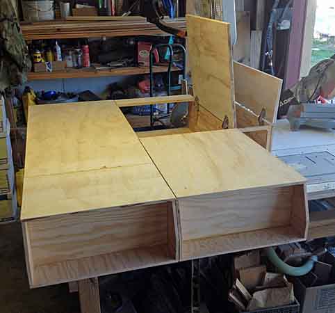
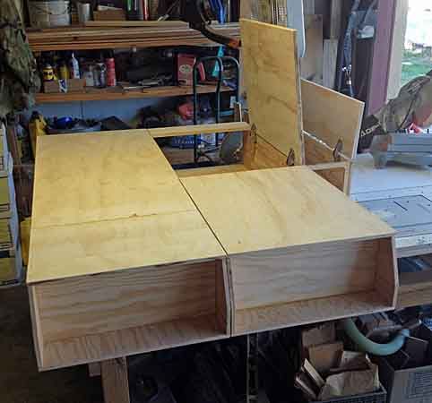
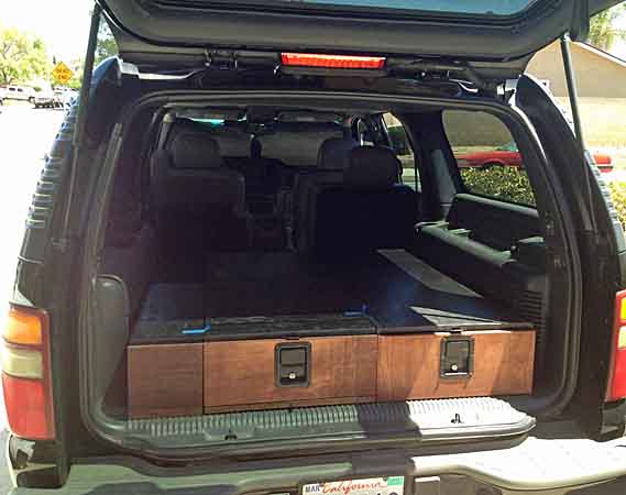
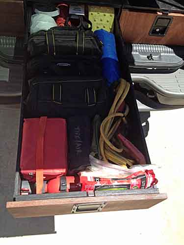
The 'complications' (besides a lot of power ports, switches, DVD stereo head unit stuff that I've been adding) come with the 'Power Module' that I'm adding to the rear cargo area and part of my Storage Drawer / Platform project, which I've finally begun - http://www.expeditionportal.com/for...e-Drawers-Platform-for-my-GMT800-Suburban-WIP

The concept on the Power Module is to be able to power just about anything for camping, small electronics, HAM radio and even CERT or Search & Rescue. It will also have a solar charge controller and both internal wiring to a jack embedded my roof rack rail support for a roof rack deck -mounted panel, as well external connectors on the module for jacking in a ground-deployed solar panel setup.
Each end of the power module will have a wide variety of connections available, 12vdc cig lighter / power ports, 5vdc USB ports, 12vdc Anderson power Pole connectors and 115VAC electrical outlets. And probably two of each kind on both ends. So totally accessible from inside of the vehicle and from the rear with the Liftgate raised.

Also inside the power module and under the hood there will be marine-style rotary battery cutoff switches on the main supply to the front and rear couplers for the hitch. So they'll be dead until needed. I'm also modifying a set of heavy jumper cables so one end uses a large Anderson power coupling, so I can detach that set of clamps and jack the jumper cables into that rear bumper connection, to be able to jump a vehicle from my rear bumper, a la the 'slave cable' arrangement on military trucks.

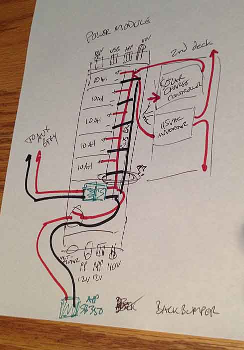
I am ALSO considering adding some compact 10.5Ah sealed lead acid 12VDC batteries inside of that Power Module. I think I can fit 4-6 of them in the available space. Right now I 'm not sure how those will be connected to the whole system. They will likely depend from the solar charge controller. But the solar charge controller will be fed by both rooftop solar and from the aux battery. Not sure if that's even possible, not sure I can hang things together in a series like this, with disparate battery types.
I think I COULD do it if I keep the rear batteries isolated from the Aux until the vehicle is off. Then the under-hood relay / solenoid decouples the Aux from the Starter battery and I flip a switch to manually connect the Aux to the Solar Charge Controller. I'll eventually have a thin-film solar install on my roof deck, always feeding the solar charge controller and keeping those rear batteries topped off.

Here's a couple rudimentary diagrams to convey what I'm imagining / intending.
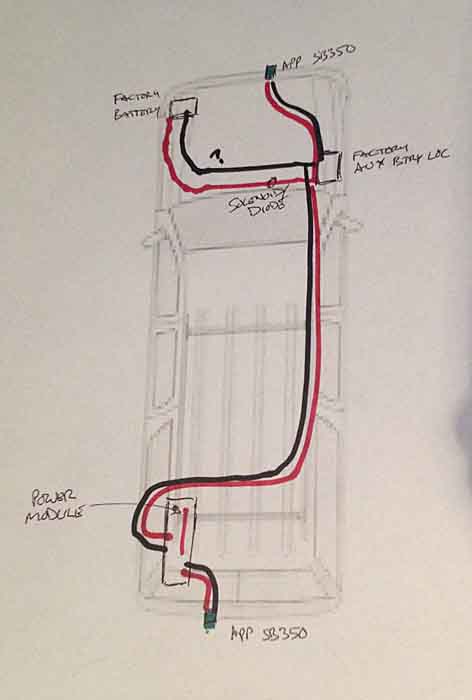
powermodule01.jpg
powermodule02.jpg


So my questions are many, what is possible or impossible about this? How best to couple or NOT couple the various subsystems? What am I forgetting, or have wrong?
And how do I do it as inexpensively as possible. I'm looking for the intersection low budget and reliable. I'm not throwing any $400 dollar parts at this. In fact I'm hoping to do the whole thing for less than that.

Lastly, The entire lid / top deck of the power module will be hinged and readily opened. And there will be Class C extinguisher(s) nearby. And I'm also considering an external breaker(s) on the box, so power to it can be swiftly killed.
 
Last edited:

Bear in NM

Adventurer
One suggestion would be to look at the Sunsaver Duo charge controller. In my portable system, I used both a standard controller and the Sunsaver Duo. My thoughts were that the Duo allows charging to two battery banks, easily. If you do install batteries in your Power module, that will give you three batteries to charge (as I also have), and having the flexibility is pretty nice. I have my suitcase batteries (similar to your Power Module battery) hardwired. The second Duo port is set up with plugs, compatible with lines to my starter or truck Aux battery.

Craig
 

rayra

Expedition Leader
That's an interesting idea, I had thought to use the panel and controller to keep the aux topped off or the added sealed batteries once I added those.
What has me concerned is is having all the subsystems connected together. I don't think I can properly get away with having the primary and aux getting charged by the alternator while also having the aux connected to the smaller battery subsystem.
And if everything is connected then when the vehicle is running and the solenoid / isolator is 'closed' then all three battery setups would become a load on the alternator. And different capacity batteries connected at the same time is bad juju, from what I understand.

I think what I want to do is have the aux battery as a power source to the solar charge controller, same as the panel(s). That should segregate the Power Module batteries from the Alternator / Starter / Aux setup. And that way I can power all the ports and inverters in the Power Module from the local batteries via a local bus / fuse panel. And indirectly from the Aux, thru the solar charge controller.

But that is then further complicated by the heavier cabling from the Aux, which is switched thru the Power Module to feed the back bumper connection.

I can run the fat feed from the aux to the Anderson coupling and make that a mounted receptacle in the cargo sidewall, with its rubber cap. And have that line up with an access hole in the side of the Power Module facing the cargo bay wall. Then in the module have a terminal / post setup with a short lead and matching plug. This connects the Module to teh vehicle power. And a feeder line can go from that post to the input on the solar charge controller. Then another fat lead and coupler comes from that terminal post and plugs into a second cargo wall connector that leads to the back bumper.

I'm pretty sure the big Anderson Power Pole connects can also mechanically stack or at least be bolted together. I can make a dual plug. Just have to figure how to plug and unplug that fat ****er without getting shocked or starting an electrical fire. I guess that's where the rotary cutoff in the engine bay at the Aux comes in. I can kill power to teh whole mess while I'm jerking around the fat connections.

It will be a few more days before I get the basic construction on the storage platform stuff done. Then I can focus on mocking up components in the Power Module and start producing some more detailed schematics to be picked apart.

eta the 'Power Module' is that smaller lidded box on the right.

storagebuild031.jpg
 
Last edited:

rayra

Expedition Leader
There are various mounting brackets available for all the Anderson power Pole (APP) connectors, including the very large ones.

$(KGrHqR,!qoE-Z(JsHVzBPqTvq!fZ!~~60_35.JPG
mtIp15XnsPIwvBln6vek1Yg.jpg


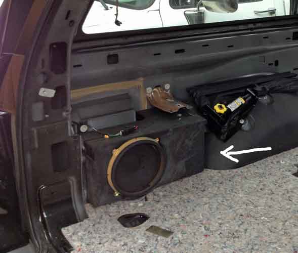
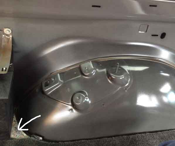
I have the spot in mind for penetrating the floor and mounting the couplers. It's right behind the rear wheel well and between it and the factory subwoofer box. In fact the side of the box would make an excellent fixed mounting location.

powermodule03.jpg
powermodule04.jpg


That mounting location falls about in the middle of the side of my 'Power Module' box. Easy to cut a hole in its side and in the cargo bay trim panel. And have a matching 'pigtail' within the box with enough cable slack to allow manipulation of the connectors.

And a 'jumper' could be rigged to connect the cargo wall connectors if the power Module is dismounted. Or for that matter the 'hot' connector could just be plugged directly into.
 
Last edited:

DiploStrat

Expedition Leader
That's an interesting idea, I had thought to use the panel and controller to keep the aux topped off or the added sealed batteries once I added those.
What has me concerned is is having all the subsystems connected together. I don't think I can properly get away with having the primary and aux getting charged by the alternator while also having the aux connected to the smaller battery subsystem.
And if everything is connected then when the vehicle is running and the solenoid / isolator is 'closed' then all three battery setups would become a load on the alternator. And different capacity batteries connected at the same time is bad juju, from what I understand.

Can't comment on the other aspects of your concept, but connecting all of the batteries together, when they are on charge, is exactly what you want to do, assuming that they are have grossly the same charge requirements and your charger matches those requirements. In this case, recent Suburbans are set up to charge AGM batteries, probably Lead Calcium formulation. (Typically a slightly higher voltage.)

You want the batteries disconnected when they are discharging.
 

Bear in NM

Adventurer
Ray,

Looks like a plan. I made the mistake of using an off brand of the big connector from my aux truck battery, to the rear underside of my Av bumper. The male to female are a little tough to slide in and out, already. And I found that my rubber boot, same design as you show, does catch water. At least it did while hosing my truck down, on Sunday. You will be inside with yours, so not a problem. I am going to have to plan a visit to the APP site, and place my next order direct. I did the big connector to someday maybe add a winch, but tapping into the same line, I have a couple of APP 30 amp connectors in my bed, under the bed covers, to plug in my fridge when rolling. So right now, I have minimal loads on my aux truck battery. When in camp, everything gets moved to my portable solar controller box. But the big APP plug on the back also lets me charge my aux battery from the comfort of my carport. This will be better this winter, when I want to charge my truck batteries when it is cold and/or snowy.

But I will be following this to see how it goes, as I may add a battery to my off road trailer, then I would have 4 batteries to deal with. Oh, I think the big on/off switch is a great plan for the lines. I placed one on my aux battery, so that I can safely work on things, and to allow me to disconnect the aux battery system in the event I ever take the truck to a repair shop.

Craig
 

rayra

Expedition Leader
Can't comment on the other aspects of your concept, but connecting all of the batteries together, when they are on charge, is exactly what you want to do, assuming that they are have grossly the same charge requirements and your charger matches those requirements. In this case, recent Suburbans are set up to charge AGM batteries, probably Lead Calcium formulation. (Typically a slightly higher voltage.)

You want the batteries disconnected when they are discharging.

Yeah, I get that basic concept, but I'm trying to figure out if the smaller SLA batteries I'm considering adding within the Power Module should be part of the pool getting charged by my vehicle's alternator. I'll have either Group75 or 78 SLA as my Starter battery and Auxiliary (a matched pair). I'm not sure the smaller batteries ought to be in that charging pool.

eta - I'm deliberately avoiding deep cycle / AGM, trying NOT to create an 'off grid' House setup, even if I'm sort of using it that way. I want redundancy for my Starter battery with my Aux. I'm trying to add additional battery capacity in the Module as the supply for true 'House' functions. As well as avoiding (for now) the much higher costs of AGM / Deep Cycle setups.

I'm trying to figure a way for the Module stuff to use the Aux as a power source, without the added batteries being 'seen' by the vehicle's charging system. I'm not even sure I understand the issue(s) correctly.

I have a more detailed diagram in my head, but won't have time until late today to lay it out on paper and post it. What I'm envisioning is hanging the whole Module mess off the main cabling from the Aux to the back bumper via a smaller feeder from that cabling to the 'input' side of a solar charge controller. Then the added smaller batteries are charged thru it and all the power connects, inverters etc are fed thru a fuse block attached to the smaller batteries. If I understand things correctly, that will segregate the smaller batteries from the issues related to hanging disparate batteries on the charging circuit. The solar charge controller just acts as a drain / draw.
And in this way all the module stuff is isolated from a big drain such as with using the back bumper connector to power a winch or jump another vehicle.
My initial layout would have tied the Aux and module systems together by using both to feed the Power Module's bus. The bus would have bridged it all together.

I'll diagram what I have in mind later this afternoon. I'm trying to blend together 4-5 different circuit ideas in a way that works together but segregates things. And doesn't catch fire.

But right now I have to get back to turning money into sawdust, while it's still cool.
 
Last edited:

dwh

Tail-End Charlie
That's an interesting idea, I had thought to use the panel and controller to keep the aux topped off or the added sealed batteries once I added those.

You would need two isolators. One for aux under hood and another for small bank in rear. Something like Samlex ACR160s. Good cheap auto connect solenoid isolators with dual sensing and can add an override switch and can add indicator LED.

The isolator for the rear would have to be in the rear. Reason is, you don't want to run the winch through a small isolator. So, big wire to rear, then tap that, at rear, to feed rear bank through isolator.

What has me concerned is is having all the subsystems connected together. I don't think I can properly get away with having the primary and aux getting charged by the alternator while also having the aux connected to the smaller battery subsystem.
And if everything is connected then when the vehicle is running and the solenoid / isolator is 'closed' then all three battery setups would become a load on the alternator. And different capacity batteries connected at the same time is bad juju, from what I understand.

No, Diplostrat is right, having all connected together *while charging* (alternator, shore power or solar) is exactly what you DO want. Hence the dual sensing auto connect solenoids. Apply a charge voltage anywhere and the solenoids will sense it and engage and all batteries will charge.

I think what I want to do is have the aux battery as a power source to the solar charge controller, same as the panel(s).

That's a no go. You can't use a battery as input source to charge controller, the input voltage potential will be too low to charge another battery. Solar can charge a battery only if the input voltage potential is higher than any voltage the battery will reach during charging.


That should segregate the Power Module batteries from the Alternator / Starter / Aux setup. And that way I can power all the ports and inverters in the Power Module from the local batteries via a local bus / fuse panel. And indirectly from the Aux, thru the solar charge controller.

Since you can't feed the rear battery from the aux battery through the charge controller as you imagined, now you are getting into the realm of the actual bad juju...tying different batteries during discharge. That's the juju that will chew up the batteries.

Now you get into all kinds of headaches trying to figure out how to do it. But really, the only way is to use a battery switch and switch the loads (or some loads anyway) from the rear bank to the aux battery.

Two conflicting problems make this a nightmare.
A) you need the winch running from the engine battery without going through an isolator, so that most of the power for the winch comes from the alternator, and
B) you need your rear loads running from an isolated battery.

Yikes.

I think you gotta "simplify your life".

Here's how I'd do it...

Feed the under hood aux battery with a bigass isolator like the 500a Bluesea. Run the big wire to the rear from that aux battery and engage the solenoid "always on" override when winching so that the winch get most of its power from the alternator, with both under hood batteries available to supply extra oomph to the winch as needed.

Tap off the big wire at the rear to feed your rear load box.

Forget the extra batteries in the rear, they just make the whole thing too much of a complicated PITA.

You can feed you solar into the rear box and put your charge controller there if you want. I would, it's handy. Just run the charge controller output positive to one of the fuse slots in your aux fuse block to backfeed power to the bus and charge the aux battery (and via the auto connect solenoid, keep the engine battery topped up as well).

You'll have to remember to engage the override when jumping someone off the rear, but it won't hurt anything if you forget, since the engine will be running and if the automatic solenoid disconnects when the other car turns the key...no biggie. You can jump just fine off the aux, and the solenoid will reconnect right away once the starter in the other car is disengaged.


Now if you just gotta have that extra battery in the rear then do what I just described and then also add a Samlex isolator in the rear to tie in the rear battery during charging.

But you'll have to manually switch the loads to run from either the rear or the aux, or split the loads so some are on the rear and some on the aux.

As the Captain said to the Blade Runner, "No choice pal."


But that is then further complicated by the heavier cabling from the Aux, which is switched thru the Power Module to feed the back bumper connection.

I can run the fat feed from the aux to the Anderson coupling and make that a mounted receptacle in the cargo sidewall, with its rubber cap. And have that line up with an access hole in the side of the Power Module facing the cargo bay wall. Then in the module have a terminal / post setup with a short lead and matching plug. This connects the Module to teh vehicle power. And a feeder line can go from that post to the input on the solar charge controller. Then another fat lead and coupler comes from that terminal post and plugs into a second cargo wall connector that leads to the back bumper.

I'm pretty sure the big Anderson Power Pole connects can also mechanically stack or at least be bolted together. I can make a dual plug. Just have to figure how to plug and unplug that fat ****er without getting shocked or starting an electrical fire. I guess that's where the rotary cutoff in the engine bay at the Aux comes in. I can kill power to teh whole mess while I'm jerking around the fat connections.

It will be a few more days before I get the basic construction on the storage platform stuff done. Then I can focus on mocking up components in the Power Module and start producing some more detailed schematics to be picked apart.

eta the 'Power Module' is that smaller lidded box on the right.

storagebuild031_zpsvcts5haf.jpg
 

rayra

Expedition Leader
haven't forgot about this - nor been deterred - I've been busy digging up some answers and options for myself. And along the way found that Energizer has produced a jumper cable kit that's almost identical to my idea, right down to the Anderson Power Pole connector.

https://www.amazon.com/Energizer-1-...1470900321&sr=8-2&keywords=jumper+cable+plugs


I think I've got a design layout that will let things coexist. I'll try and find time to diagram it this weekend. Basically it's running the heavy gauge wiring from the Aux into the power box, to a terminal bolt and having a lead off of that as the 12v source for most of the connections and inverters in the Power Module. Then another fat lead off that bolt and thru a marine rotary cutoff, leading back out of the box and to the rear bumper for the winch / jumper connector. Maybe even using that cutoff switch as the junction point.
There still will be an isolator between starter and aux, and a cutoff between the aux and the rear.

The other design question remaining is do I cut off the branch circuit to the other stuff in the box, when a heavy load is put on the rear bumper connector?

If I put a solar panel in, and solar charge controller in, feeding the added 10Ah SLA batts in the power module and they in turn being also connected to the same bus powering all the other ports in the module, and then put an isolator / diode on the feeder line coming from the fat cable junction, then ALL the batteries would be getting charged by the alternator, but only the power Module batteries would benefit from the solar. And I'm fine with that. I could even add a shunt that dumps the solar power into the Aux if necessary, while simultaneously leaving the Module batteries isolated.
And adding an isolator / diode on that branching line would then protect the smaller batteries from any heavy draw originating on that heavy cable line at either bumper or directly off the Aux.

If I get the layout right, I can protect against a heavy load on disparate batteries, while still allowing disparate batteries to charge. I can do that with isolators / diodes. Effectively the Power Module systems / outputs are on their own 'island' / branch circuit.

So still looking for technical info and reasons, rather than negative opinions about the idea.

meanwhile, the storage build related to this continues apace. I'll be working up more component info and mockups this weekend, while paint dries.
http://www.expeditionportal.com/for...e-Drawers-Platform-for-my-GMT800-Suburban-WIP


And I'll try and get all that diagrammed out with proper symbology and components, too. I don't think what I'm attempting to do is much different from some RV and Off Grid power systems that are all over the internet. I'm just trying to do it in a Suburban and add a couple more useful features to the underlying architecture of it all.
 
Last edited:

Bear in NM

Adventurer
I have no technical reason to not have other loads plugged into a high load line while under such a load, but in my system, if I ever get my winch installed, I had plans to disconnect my fridge, if I had to winch. Historically, I never had issues while winching in the dark with headlights on, or wipers, etc. when using only one battery, but in my simple mind, disconnecting a 1200 dollar fridge from the line seems like a reasonable precaution. I am guessing that the location of your module box (in your other thread) is designed to be accessible from the passenger rear door, and not to be buried by a ton of camping gear? If a disconnect is not a major headache (wiring complexity), probably not a lot of downside to having the ability to isolate the parts. I guess I am just paranoid.

Craig
 

dwh

Tail-End Charlie
There's really no need to disconnect the aux fuse block. After all, you won't be disconnecting the chassis fuse block when winching.

As to the fridge mentioned in the previous post...it has a low voltage disconnect built-in and will disconnect itself is the winch (or the jump start or the inverter) pulls down the bus voltage far enough. The inverters will do the same.

The diode isolator will work, just be aware of the voltage drop through the diode.
 

rayra

Expedition Leader
You two aren't anywhere near as subtle as you think you are. I'll take it as given that you don't like the idea, going forward. Guess I left the door open with my request for inputs. Guess I should have narrowed it to technical review instead of opinions on worthiness.

I have multiple reasons for adding the stuff I am. Lost my home to the Northridge quake and I'm still in the region. Getting involved in CERT and HAM radio. An amateur astronomy hobby that benefits from such power sources. As well as other outdoor off-grid activities. Road trips and a desire for some future trips farther afield to several national parks and up the Sierras re-creating some of Ansel Adams' treks and photography. So while you both say 'too complex, don't do it' with your koans, I'm pressing on. With your technical assistance, or without it. Preferably with it. If you can get past your own naysaying.

Just finished a bunch more work on the storage platform system and have a variety of power port adapters inbound via amazon, as well as a second battery tray. It will be several weeks before I start laying the wire to the rear power module. Initially I'll drive everything off the aux battery. But I still want the additional batteries / Amp-hours and the solar. And while I can isolate the 3rd battery(ies), I'm still trying to figure out how I can connect the solar charge controller in a way to passively charge both the Aux and the 3rd batteries, without bridging both systems together on a discharge, and without having to actively switch things. Yet another isolator I presume.

I'll get the updated circuit layout worked up as soon as I can, maybe I can get some useful technical help on it. Work continues.

storagebuild089.jpg
storagebuild092.jpg


http://www.expeditionportal.com/for...e-Drawers-Platform-for-my-GMT800-Suburban-WIP
 
Last edited:

dwh

Tail-End Charlie
Like or not like doesn't enter in to it. I've got no emotional investment. My reply was purely based on the technicalities involved. There were no hidden messages.

I generally start out with a list of the problems, a way to do it that I think eliminates as many of the problems as possible, and then how I'd do it if the OP insists on doing it his way anyway.

Which is my SOP and is exactly what you got.

And yes, as I already stated, the third battery is going to involve another isolator.

And load management is going to an issue that will have to be taken into account.
 

Forum statistics

Threads
188,045
Messages
2,901,566
Members
229,411
Latest member
IvaBru
Top