Designing a complicated power infrastructure, seeking inputs on my inputs and ouputs

rayra

Expedition Leader
Dunno, that 40mm has the power to evacuate the total volume of that box every 15 seconds. Isn't that enough airflow?
But if I'm every operating the large inverter for an extended period I'd probably leave the box open anyway.

Still shopping sizes and shapes and features, found this 2000W KRieger unit, proprietary faceplate so I'd have to remote the plug somehow. But it has a swell remote faceplate with status light. Just the thing for the wall in an RV or trailer. And unfortunately, the inverters get pretty big once you are above 1000W, as do theirs. This unit would fill roughly 1/4 the internal volume of the box. Can't really afford that. Too much other crap I want to put in there.

https://www.amazon.com/KRIËGER®-200...0301&sr=8-3&keywords=2000+watt+power+inverter


So still looking around, maybe a 1500W in a smaller footprint with a peak / surge near twice that and I can get away with running a table saw or electric chainsaw. And certainly my circular saw and smaller powered hand tools.
I wonder what the load numbers are on my Sawzall. I have a 'Kill-O-Watt' meter, maybe I'll check it out tomorrow, after I finish carpeting the storage drawers.


eta

a new challenger emerges

https://www.amazon.com/ERAYAK-Allig...1505&sr=8-6&keywords=1500+watt+power+inverter

nice compact size, good reviews. 1500W
 
Last edited:

4x4junkie

Explorer
Dunno, that 40mm has the power to evacuate the total volume of that box every 15 seconds. Isn't that enough airflow?

I think you'd need to exchange the tiny volume of air in there much more often to effectively draw out the heat of a 1000W inverter (I imagine the inverter's own built-in fan is much larger than 40mm, probably 60 or even 80mm). I guess you could try it and see how well it works, though I would suggest leave yourself enough room to mount a larger fan just in case.

FWIW, I have a 1500W (3000W surge) inverter myself (it's an older Statpower MSW unit). I've run a jigsaw, drill, 4.5" angle grinder, Sawzall, and a 2×500-watt halogen work light on it no problem (not all at once of course). I could not get it to start up two different circular saws though (both 7¼" saws), the start-up surge apparently was too much for it (it would try for about 1/8 second, then shut down, not enough time for the blade to get up to speed). I suspect a 2000W (4000 surge) unit would be the minimum needed to get a circular saw going.
 

rayra

Expedition Leader
I've got a smallish computer UPS laying about, I'm wondering if it could be used like a capacitor in such a situation. PLugged into a 1500W inverter or even my 900W tiny generator, charged up and providing the surge / peak power for the motor starting, while the steady flow of the inverter or generator is enough to sustain the saw in operation and still make good the drain on the UPS battery.
I've got my Kill-A-Watt meter sitting on my workbench now, planning to run thru a bunch of my tools and get peak and steady readings. I already know my mini generator won't handle my saws.

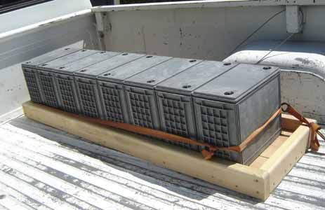
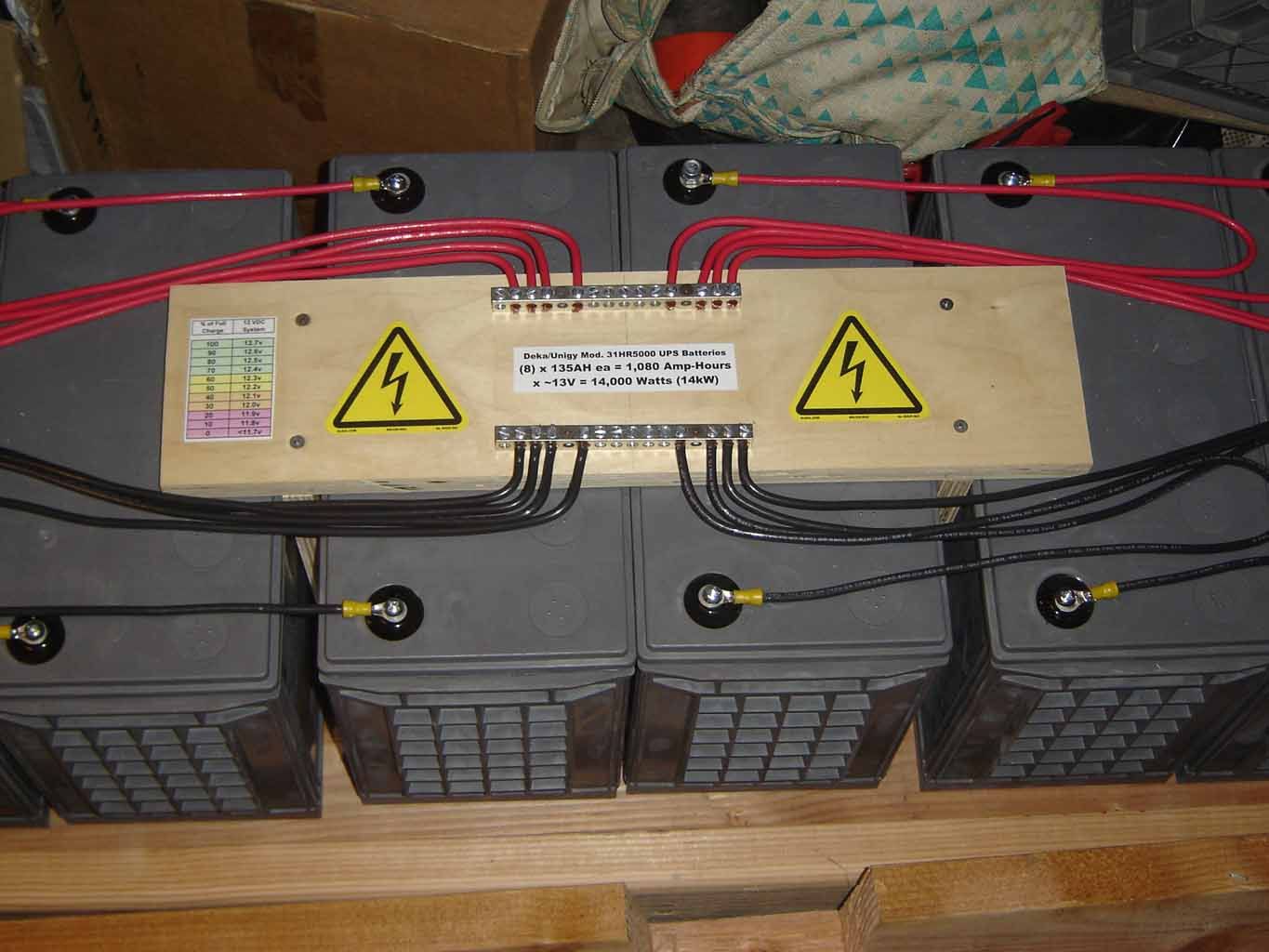
Some time ago I was fortunate enough to lay hands on (8) Deka AGM batteries from a mega-UPS, in good shape. My idea then was to create a home UPS that would charge from both grid and solar power and it would feed a couple deep freezers. I got the batteries set up in a 'tending' setup and the rest sort of fell apart as other things changed. Eventually the batteries were moved along to some HAM guys to use as a UPS for a moutaintop repeater.

batteriesretrieved_zpsqkogj1it.jpg
battery%20array%20keepalive%20wiring%20busses%20091120_zps9fuce2uy.jpg


That was nearly 7urs ago and I still don't have a proper battery bank set up at home. Re-arranged the garage layout twice, shopped home solar to death and postponed the whole idea as I really want to GTFO of CA.


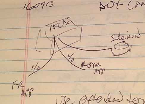
Anyway, I've got yellow sheets of paper all over my desk. Keep doodling layout diagrams for THIS system and revising things. It's too much info to cram on a single sheet / diagram. And I put it off because I didn't want to be arsed with plotting it out in photoshop with clipart etc. I'm scribbling everything down out of my head and onto paper. Then I'll take a look at it all and figure out how to make it intelligible for posting. Probably an overview / block diagram, akin to what I've already posted. Get the layout presented and the nomenclature annotated on it so we have a common frame of reference. Then some more detailed diagrams of different sections. It's further compounded as I'm planning changes over time, as well. The first version is just going to feed power to the rear Module and have all those power ports in it. The second version will add the extra batteries. The third will integrate solar charging. The 4th will feed a rear winch. And along the way I'm figuring which feeders / branches / circuits should just be implemented in the 'final' version from the get-go. And sort of working backwards from the desired end-state so I don't have to re-do or relocate anything as I go. If I just wanted to sling some mor epower ports in the back I'd just run a 4AWG branch circuit to a new fuse panel in the box and be done.
 

4x4junkie

Explorer
I totally hear ya about getting out of CA. lol This state has some great positive aspects, but the negatives are starting to get to be too much for me also. But I digress...

Yeah I don't know enough about a UPS to say whether it would work or not. I would think that a UPS is simply a pass-thru until it detects a disturbance or loss of AC on the input side, then would immediately switch via a relay over to inverting from the battery (which it's own inverter is probably only capable of a few hundred watts). This would mean it cannot actually supplement the incoming AC (it's either-or), but again I don't know for sure. If you do try it, let us know if it works.
 

rayra

Expedition Leader
I think I'm going with a 1500W inverter. It will meet all my portable tool needs and my camping needs. And it will run my emergency needs if I need to power my home refrigerator or chest freezer.
And it's about the largest class size I can fit comfortably in my 'Power Module'. The 2000W+ have a marked increase in physical size that becomes unworkable in my situation.


I ran all my portable power tools thru my Kill-A-Watt meter, running / steady draw, no load. None had a peak value more than a few percent above their steady draw.
As expected my circular and table saw exceeded 900 watts. They might work fine with a 1000W inverter, but I'd rather run a 1500 at 2/3 its rating, than keep a 1000W at max capacity.

KillAWatt%20power%20tool%20wattages.jpg


eta

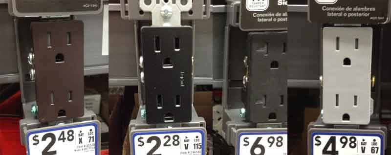
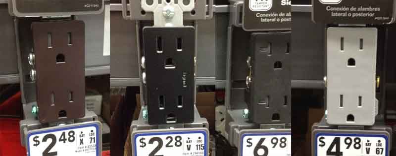
If I do go forward with the bubba-ghetto mod of remoting the inverter power outlet, I'd likely use the modern rectangular 2-gang outlets and flush-mount it in the wood face of the module. I don't htink I'd even use a plastic faceplate or outlet box. I mean if I'm gonna start an electrical fire I might as well do it up right.

powermod001.jpg


But seriously speaking, I don't really want a standard electrical outlet faceplate on the end of the box. I will likely be looking for an inverter designed with a screwed-on faceplate and consider detachign and installing that on the face of the Module. And backing it in some shielded manner back to the body of the inverter. Spark-safe.
That, or opening the wood end plate large enough to pass the entire (usually aluminum extrusion) body of the inverter, and adding a broader faceplate as a shim between the inverter faceplate and body, with the shim broad enough to cover the hole in the wood panel. That keeps it cosmetic on the outside, while keeping the inverter closed up.


And thinking more on the wiring, I think I might place the rear bumper plug feeder and the inverter and the box ventilation fan wires on the same terminal on the rotary switch. So turning it on to provide power to the inverter turns on the box vent fan. Maybe. As that doesn't do much good later when the solar charge controller is in and doing its thing.
 
Last edited:
rayra

Expedition Leader
GMT800 Auxiliary Battery Tray Install

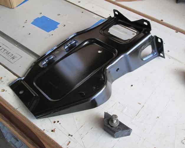
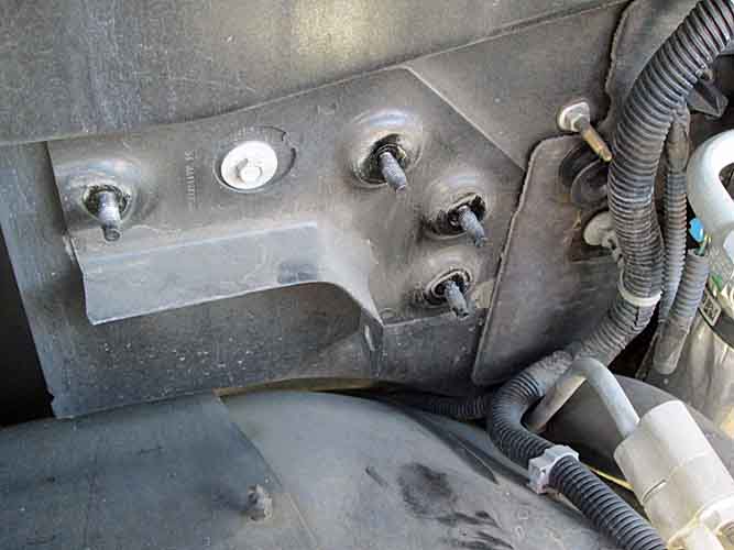
I've got various shipments coming in for my dual battery setup, but I saw my 2nd battery tray was due today so I made time in the middle of packing for a weekend road trip to make ready and whip it in. Took about 25mins.

The tray is available on both Amazon and rockauto.com for about $30. It replaces some bracketry in the passenger-side hood hinge area and allows a matching group 75 or 78 (factory equipment on GMT800 vehicles) to be installed. Group34 roughly same as 78, just a top terminal vs side terminal. The tray re-uses the mounting hardware of the lower bracket you remove.

auxbatt001.jpg


The reservoir / overflow tank shares one bolt with the lower tray. It's also bolted down under the corner of the factory air box. There's enough play to lift and tip the tank toward the centerline / engine and get clear of the lower bracket and battery tray install.


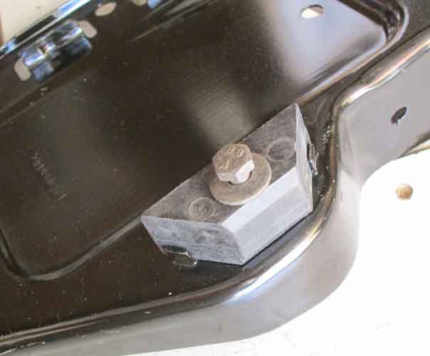
The heavens sing:

auxbatt002.jpg


That odd-shaped piece is the battery hold-down and is NOT included. I had one laying around courtesy of a plan to install a 2nd battery in my C-10, 20yrs+ ago. It exactly fits this new bracket, 27 model years later. That's pretty 'thrifty' of GM.

auxbatt004.jpg


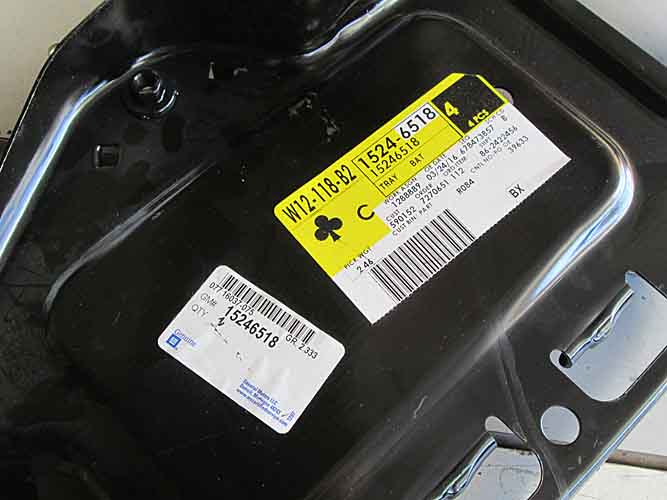
Model number

auxbatt003.jpg


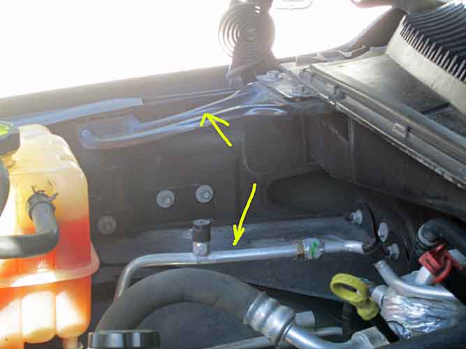
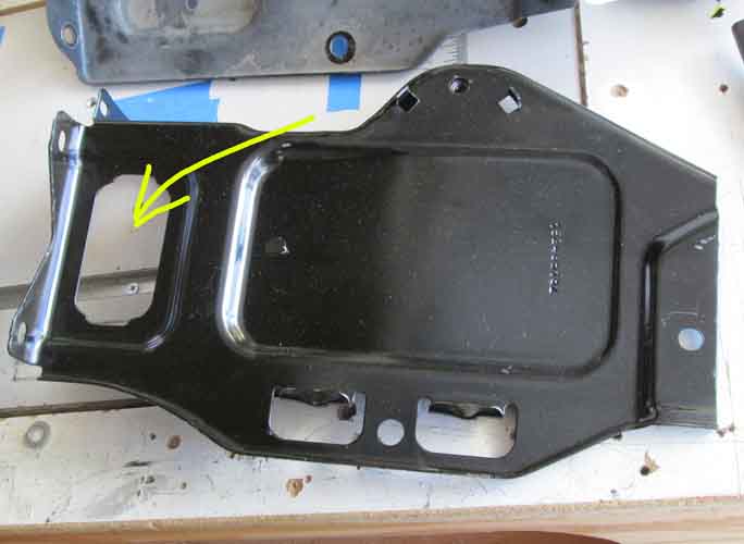
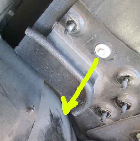
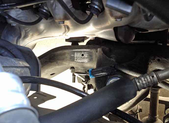
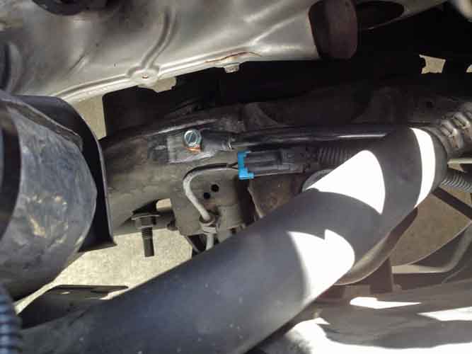
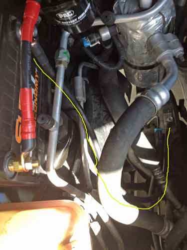
As I worked the install I noted the large opening crafted in the tray. Given the room left by my using Grp75 batteries (about 1.2" shorter in length than a Grp78/34), and my plans to run some heavy cabling to the rear of the vehicle down that rear corner of the front wheel well to the frame rail, that hole seems like a likely pathway if I really try to tuck things away.

auxbatt005.jpg


But the edges of that stamped steel are quite sharp. Heap bad juju for 1/0 cabling with ~200A rubbing on it. So I cut open some 3/8" fuel line I had laying around to trim it out. A proper pinch weld trim would be better, hold on better. For all I know there's a factory plastic insert for that hole.

.jpg


The mounting bracket on the firewall has a similar sharp edge to worry about, it protrudes about an inch below the hole in the tray. So it got the same treatment, using some 1/4" fuel line, so it would hold there better. The yellow arrow would be the approx. path of the 1/0 cabling

auxbatt007.jpg
auxbatt008.jpg


aaand I forgot to take a pic of the tray installed and the alignment of the now covered edges.


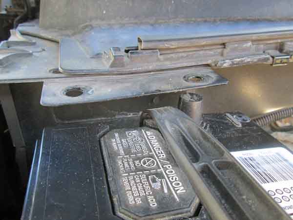
There isn't much clearance between the cowl tab of the old top bracket and the top post on my Grp75 battery, And a 34/78 would be further under there. That's the negative terminal.
In the near future I might cut that bracket tab off. But when I get another new 75 battery there won't be any top terminals anyway. The battery pictures is the 2yr-old cheap POS that was in the Sub when I bought it. It started having some trouble during our recent heat wave and my incessant fooling around with my new in dash DVD player and charging ports installs. So I just recently bought a new Interstate 75. The old battery seems to be holding a charge after a proper recharging, so I'm going to use it up as the Aux while I get my electrical upgrades installed.

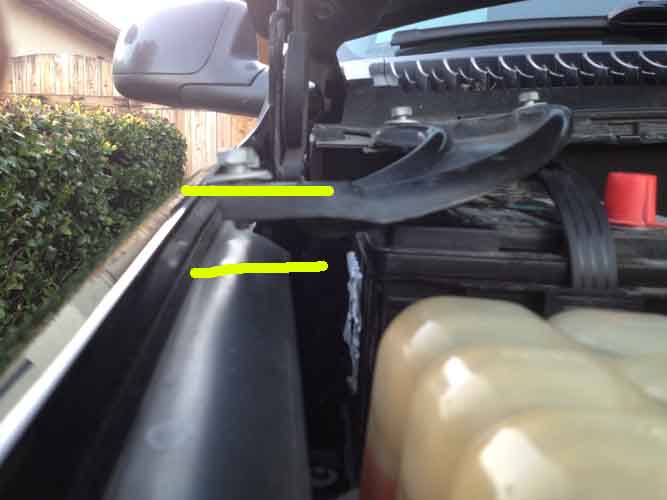
I forgot to check if that upper bracket will re-install over the battery , I don't think it will.

auxbatt009.jpg


eta yeah that's a No, not even close on putting that bracket back in, unless your battery is about 1.5" shorter in height than a Grp75

auxbatt010.jpg


There'll be more on this next week as my 200A isolater and copper terminal ring lugs arrive and I get some 1/0 cable for my Aux battery charging circuit. Could have gone much lighter as with the '$50 Dual Battery' plan, but my later plans will involve heavier cabling so I'm starting out that way from the get-go.
 
Last edited:

Bear in NM

Adventurer
Rayra,

I did my tray from GM Parts Direct. I know they are a little pricey, but at least I have the schematic so I do not miss any necessary parts. My primary battery, as well as secondary use those bottom mount pucks for hold downs, and they being my first that do not use metal rods, I am a lot concerned. I tend to check mine frequently. Yes, I too eyeballed re-installing the fender brace, but certainly a no go. I have not looked at the newer models with the primary battery in this position to see if there is additional hardware, but not really fretting over it's removal.

Please let us know when you figure out how to shoe horn a larger amp hour battery in there. If anyone can pull that off, I suspect you can:D

Craig

Oops, forgot to mention. If you decide to try and run your cabling inside the frame rail, it can be easily done with a plumber's snake. I did this with my backup camera wiring, and added my battery cable to the rear. I know this puts the wire in a place that it cannot be inspected, but it is also a place where the wire is well protected.
 
Last edited:

dwh

Tail-End Charlie
Aye, packing the the wires into a one gang box with those can be a challenge.
 

rayra

Expedition Leader
Spooky. Just did EXACTLY that this weekend. Traveled out of town to help my nephew and his wife commence a complete master bathroom remodel in their new-old house. Fought like hell to get that Leviton-USB jack crammed into a 1-gang box along with 3 sets of 14-2 romex connections and their nuts / pigtails. Only to realize I had to do it all over again because the GFCI outlet had to go in that location to protect the other downstream outlets.

auxbatt012.jpg


I'm completely wrecked. Getting too old for this ****. About 45hrs of remodeling work since saturday mid-day, just got home a couple hours ago.

But my last batch of parts orders arrived while I was gone, so the Aux battery setup will likely get done by the end of this coming weekend. Just as soon as I get uncrippled.

auxbatt011.jpg
auxbatt013.jpg


Bear, don't worry about that hold-down. The very same-design part has been serving on my C-10 pickup for well over 300k mi. and 30yrs, and a LOT of washboarded desert southwest roads. I've broken at least 3 radiator overflow reservoirs over the years from those vibrations, worn out several batteries, but the hold-down just does its job.
 
Last edited:

rayra

Expedition Leader
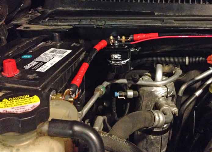
Although I can fit (3) 1/0 terminal lug ends on the extended battery bolt - feed in from the solenoid, feed to the front bumper APP plug, feed to the rear bumper / Power Module - I'm more likely to put (2) on the Aux side of the solenoid - feed to the Aux battery and feed to the front bumper - and then on the battery (+) put the feed in from teh solenoid, the feed out to the rear and a terminal-mounted 4- or 6- slot fuse panel. Feeding my aux lights and HAM and CB radios.
 

rayra

Expedition Leader
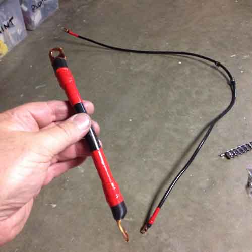
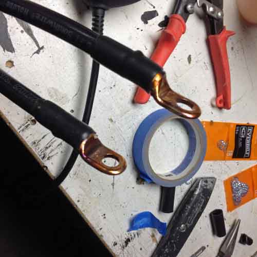
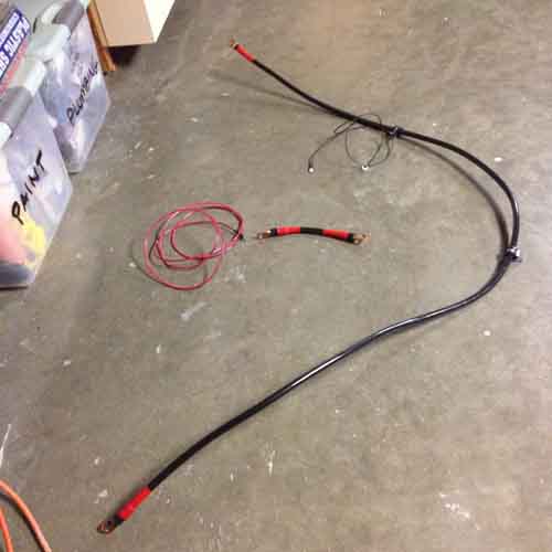
So I took my first crack at fabricating heavy cables this evening, I think it went splendidly. A bit like wrasslin' a boa constrictor, though. I bought 20' of 1/0 cable, and started off by soldering lug ends on both ends. Then wasted a lot of effort trying to wrangle that monstrosity around. So I took some rough measurements and attacked it with long-handled pruning shears - which by the way worked a hell of a lot better than the bolt-cutters the guy at Home Depot used to mangle-cut the cable

Anyway, I watched a few YouTube vids on cablemaking, methods of soldering the lugs on and got right to replicating that effort with my equipment. The parts were shiny and new so I decided to forego using any flux. Just this weekend I was sweating copper pipes in a bathroom remodel (full gut and layout change) for my pseudo-nephew. So the torch soldering skills were fresh as could be. So it was set the lug in the vise, cut some segments of fat solder into its cup, and heat / melt it up. Then once melted, work the exposed strands of the cable and the lug both for a bit and EASE the cable into the end of the lug. If you plunge it in too fast molten solder squirts out.

Here's the last one I did, the new ground cable for the Aux battery -

auxbatt011.jpg


Terminal lug orientation is vital on these cables, you aren't going to easily twist them into the correct orientation after the fact. And even if you can, you'll be putting a lot of strain on the battery terminals you connect to. So better to pre-fit the cables and mark orientation on them so you get the lugs close. Likewise, try to pre-bend and generally shape your cables, before soldering their ends into a lug.

Here's the very short run from the isolator to the positive no the Aux.

auxbatt012.jpg


Progress

auxbatt013.jpg
auxbatt016.jpg


Worked to about midnight then gave up in the middle of the install. Couldn't mount my new negative where I wanted it, couldn't find the rivnuts I'd bought, nor a spare battery terminal bolt.

So tomorrow I have to solve those issue and then figure out which switched circuit I'm going to attach the solenoid signal wire to. And how to do that in this GMT800 fuse box. But all the cables are built and most are mounted. So shouldn't take much to finish this stage and have a working 2nd battery charging arrangement.

Nope, no inline fuses yet. Still figuring the kind I want to go with. The mega car stereo market has sure cluttered up the landscape with fusing options. And driven pricing up.
And there's no load on the Aux battery for now. But I'll have fusing in place before there is.
 
Last edited:

DiploStrat

Expedition Leader
...
Nope, no inline fuses yet. Still figuring the kind I want to go with. The mega car stereo market has sure cluttered up the landscape with fusing options. And driven pricing up.
And there's no load on the Aux battery for now. But I'll have fusing in place before there is.

Use Blue Sea Terminal Post fuses. Pick the size you want, no extra installation, and you can't get closer to the power source: https://www.bluesea.com/products/5191/MRBF_Terminal_Fuse_Block_-_30_to_300A
 

rayra

Expedition Leader
True, but that bevy of cheap crap crowding the lower tier is floating the better gear to higher pricing, 'buy once cry once'.


Anyway, plugging away at a few more cables and trying to find a switched circuit to plug the isolator into. Not really any 'surplus' connections in the main fuse panel / 'power center'. Figured out how to dismantle the shroud and get access to the back side, so I can splice into an identified wire if I have to. But I've found references to a provided subpanel under the dash by the steerign column that may have some switched and unswitched connections I can use. Haven't crawled in there yet. Google search terms are 'Special Equipment Operation ' (SEO) and Retained Accessory Power (RAP). Apparently some connections ARE provided for aftermarket goodies, but they aren't in the 'normal' three fuse panel locations in these GMT800 trucks.


Meanwhile, I picked a likely spot for the negative cable on the aux battery, a pre-existing 9/32" hole in the top of the frame rail just rearward of the front shock tower bracket. Almost like it was meant for a 2nd battery install. ;) And thanks to folks at my local Fastenal store, I found a 5/16" self-tapping bolt to drive into that hole and serve as my grounding point.
First I did some scraping and solvent spraying, then some sanding, to get to clean bare metal. Then I bolted my cable down with star washers between both the frame and lug and lug and bolt head. Bolted it down nice and snug, then shot it all with some black satin enamel. Was a good reasonably accessible spot, too. A few ratchet extensions and I was able to easily drive the bolt in.

auxbatt014.jpg
auxbatt015.jpg


A lot of PITA putting the cable in and taking it out, shaping the cable, trying to put some bends and twists on it such that there was no load / strain on either of the end mountings, particularly on the battery post. This 'Aux' battery is the cheap POS that was put in my used Suburban just prior to my buying it. It's 2yrs old and on its way out. But after a conditioning full re-charge, it seems to hold charge well enough to use and it's serving as a 'stand-in' of sorts, while I get all the components together. And if it lasts another year (or not), I'll buy another fresh Interstate battery from Costco for my Main battery and bump its current twin to Aux duty.

Here's the simple bend / path for my Aux ground cable

auxbatt017.jpg


Which photo also reminds me - I had to modify the PAC 200A isolator a bit. The clamp collar on it is mounted at the midpoint on the Isolator body. Given the shape of the cowl / firewall ni that mounting location, it put the wire-mounting lugs very high and close to the upper lip. Wasn't really any room to go lower, without crowding hard against the Aux battery. And the band clamp on the isolator has its screw pass thru a lug / key cast right into the body of the isolator. So I took a stab and drilled a new hole higher up on that key so the isolator would sit lower. Got away with it, there's enough access now. But I still pre-attached the ground wire on the isolator before mounting it for good, that terminal being on the back side and still hard to get to.

So today I'm going to go for the isolator switched power source wiring connection and take some battery voltage readings both key off and on / running, to see that my isolator is working as it should. Then finish my under-hood LED engine bay lighting and finish fiddling with DVD player / EQ settings for my replacement speakers install. Then it's on to picking and ordering the next round of components for adding loads to the Aux battery.
The Blue Sea stuff is nice, but what a price premium. $17ea for fuses?
 
Last edited:

rayra

Expedition Leader
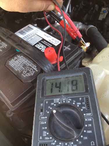
Success!

auxbatt018.jpg


That reading was 12.31VDC with the vehicle off (been 3 weeks since I took it off the charger). The reading as shown is after starting the vehicle, with it running. And the reading as shown is only a few milliamps lower than a reading taken at the Main battery terminals. Almost no loss thru the isolator.


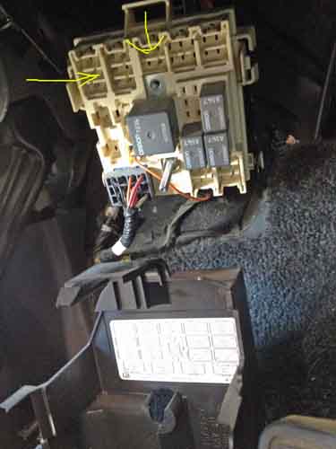
Found some online references to a subpanel under the dash by the steering column which had some switched power sources. I'd left enough length on my power supply line for the isolator anticipating a worst-case splicing under the main fuse panel. I was able to pass this thru the firewall penetration of the main wiring bundle, between the master cylinder and throttle controls.
I had to bastardize a regular spade connector but it's not really on very well, the panel prongs are quite narrow. So I'm thinking to find / source the factory connectors for that fuse block. Or scavenge some from the auto wrecking yard, next trip.

Page B-8. Although mine is a 2002, the layout was much the same as shown in this PDF.
https://www.gmupfitter.com/publicat/2004_BB/2003_Beyond_LD_Electric_CK.pdf

auxbatt019.jpg
auxbatt020.jpg
auxbatt021.jpg


eta the topic that led me to the panel solution
http://www.duramaxforum.com/forum/g...to-mbec-mid-bec-relay-center-2003-2007-a.html
 
Last edited:

Forum statistics

Threads
185,815
Messages
2,878,490
Members
225,352
Latest member
ritabooke
Top