Yes, thank you, I am familiar with the power multiplying effects and will make use of them. I also need a good sand anchor and and longer cable, as there's a dearth of trees in my usual haunts.
MagicMtnDan, here's roughly how -
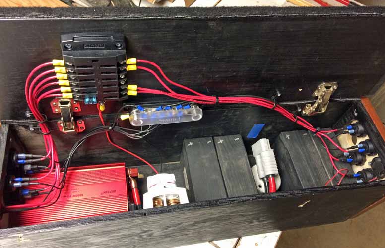
Fiddling around some more with the internal arrangements for my power module. I think I have all the parts I need now. Just not sure yet about the optimum arrangement. And I'm trying to hold options open for a later addition of some small sealed lead acid (SLA) batteries and a solar charge controller, in conjunction with some roof mounted or external (on the ground?) solar panels.
The components are big and blocky, the space is small, but I think I'm figuring it out.
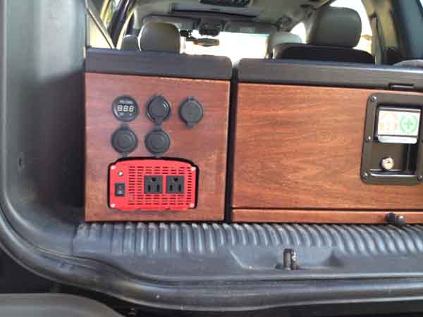
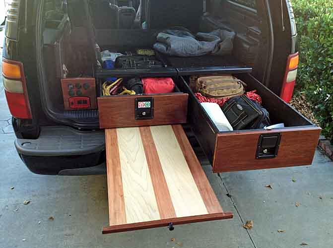
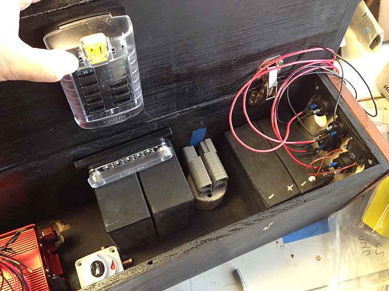
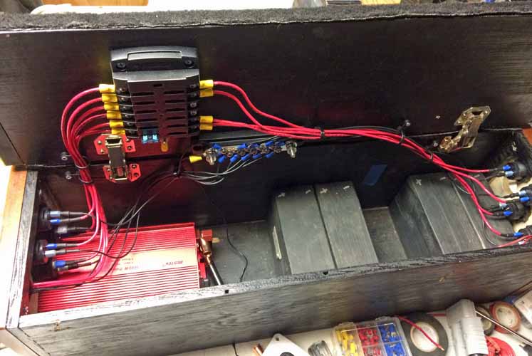
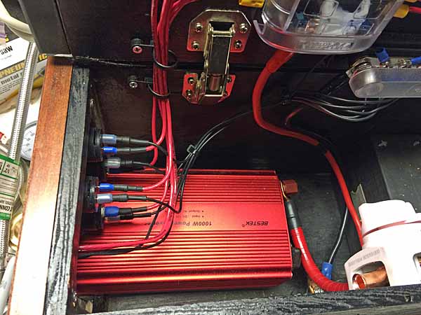
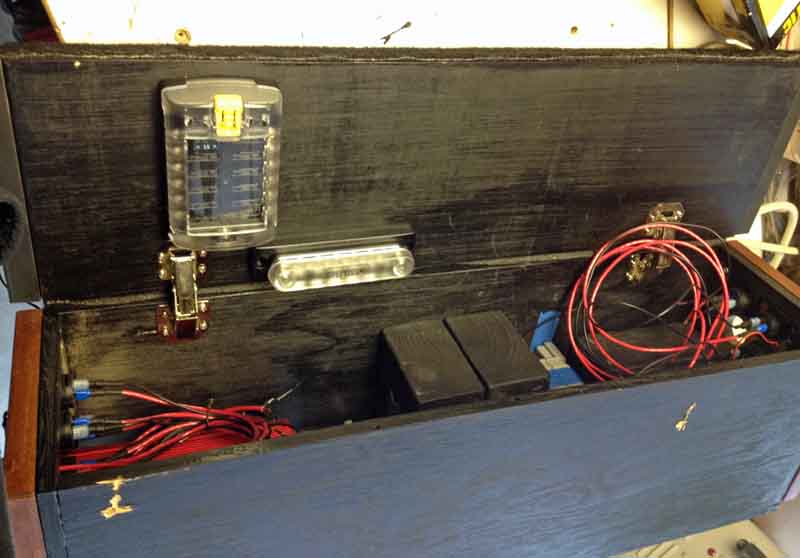
I'm mounting a large fuse block to the inside of the lid of the Module. As well as a separate grounding bus bar. They'll be mounted closer to the Liftgate end of the vehicle for easier inspection and servicing. Each power socket on both ends of the Module will be individually fused. I was originally going to fuse each like socket on each end to a single shared fuse, but it was only a few bucks more to provide a separate fuse for each.
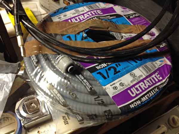
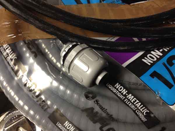
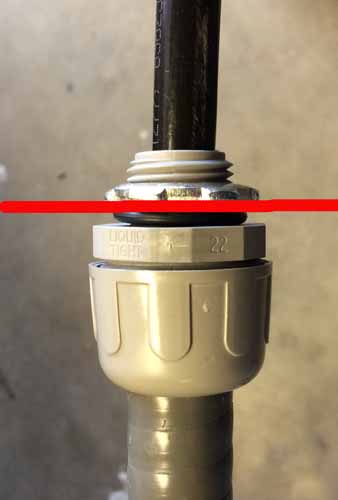
I'm going to be using plastic flex conduit with their compression bulkhead fittings as an armored pathway for the heavy cabling to my aux battery. The 2/0 cabling just fits within. I earlier mentioned I could pass a wire snake clear thru the vehicle's box frame, but decided running two cables thru it might incur the very damage to the cable insulation that I'm trying to guard against. And I further decided just mounting the cable runs along the top inner frame most of the way was insufficient protection as well. My haunts have a lot of sharp gravel and the cables' proximity to wheel wells at both ends causes me to want more protection thus the conduit. The cables just fit thru the compression end fittings, and loosely in the conduit.
100' of flex conduit was $34 at Lowes. The connectors <$2ea IIRC. I expect to use ~70' of it. 26'+ for each main run and 4-5' for each rear hitch run.
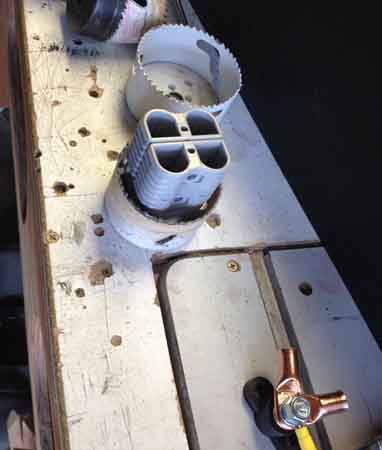
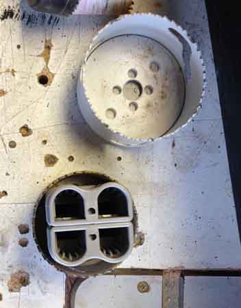
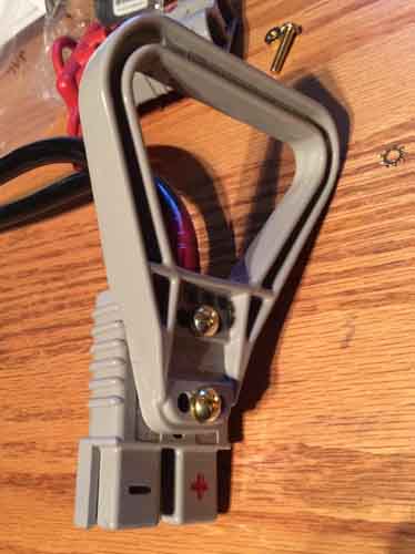
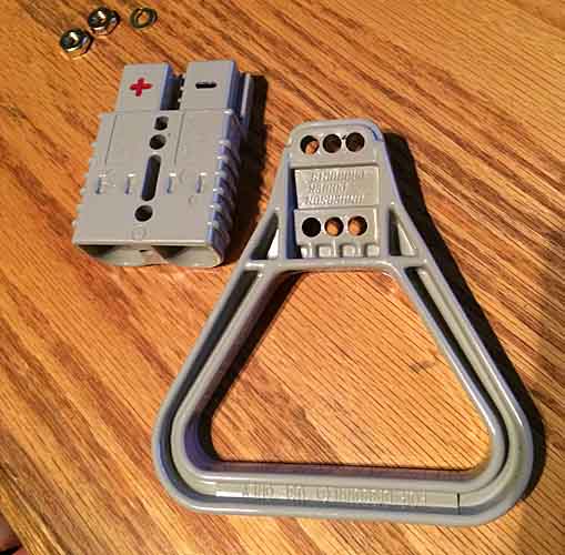
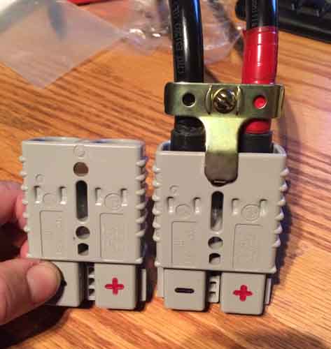
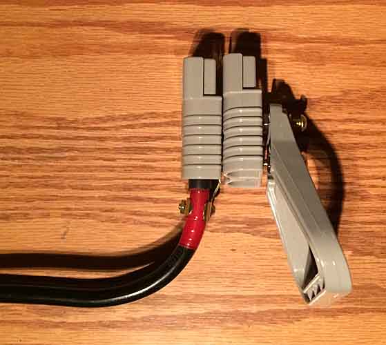
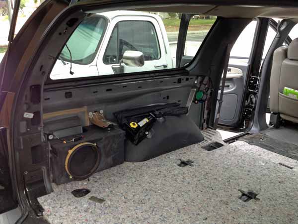
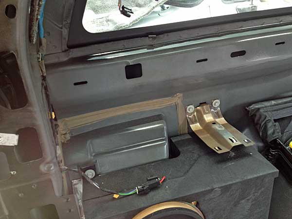
These will be routed to a penetration of the cargo floor trailing the driver rear tire, back behind the interior trim panel. They'll terminate in the large Andersen power connector, pictured earlier. That connector will be mounted with a bracket to the forward end of the subwoofer box, with the connector mouth flush with the cargo area sidewall trim panel. My further plans include another power coupling at the rear bumper for a receiver hitch -mounted winch. In my design that means stacking two connectors at that side panel mount.
I'll be stacking them base to base, so they better fit a round opening.
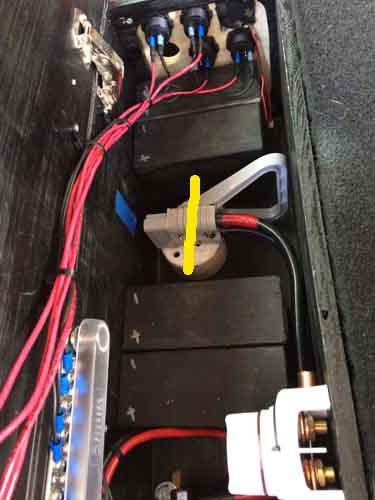
Those connectors will be mated to with a matching pair inside the Power Module. Which will have a matching hole cut in its side. Positioning of the stuff inside the vehicle side compartment dictates placement inside my Module, and that drives placement of other things inside the Module. The wood blocks are simulating the SLA scooter batteries mentioned earlier. They're about 10.5Ah ea, x4 if I can fit them. Nearly the capacity of a third group 34 battery.
I intend to route the wires from the end panel power connectors thru some anchored loom along the top edge of the Module near the hinges, transitioning to an anchor on the lid edge near the hinges, then branching to their respective fuse and bus bar connections. That will get all that up and out of the way, I'll zip tie and bundle things like a telecom / aviation install.
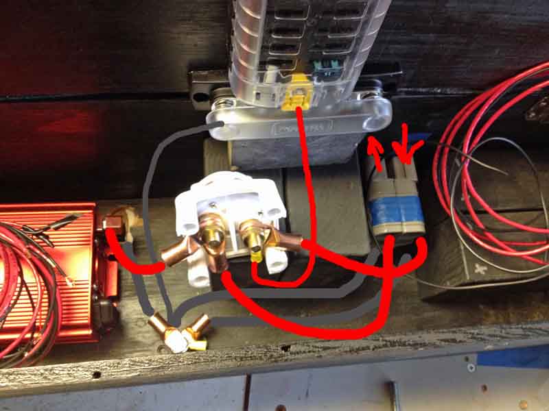
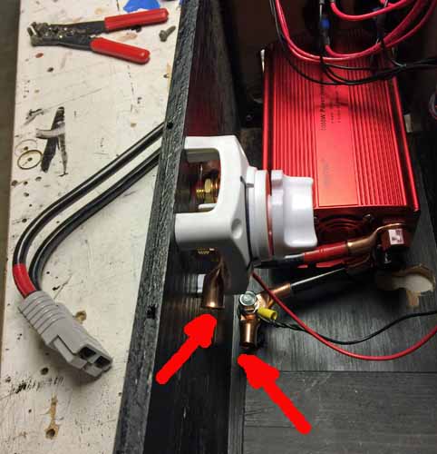
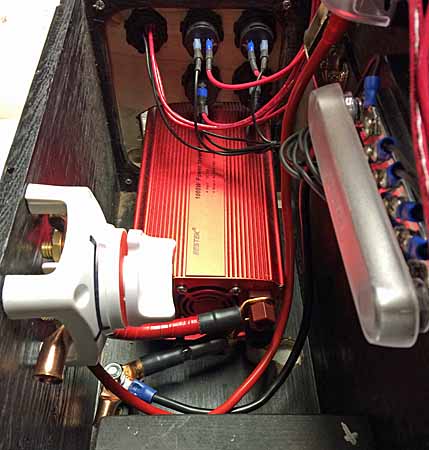
Then there's the issue of the main power distribution and cutoff. The main power line from teh Aux (+) will have a rotary cutoff at the battery terminal. Then pass thru the anderson coupling to the Marine rotary switch (white component in these pics). It will be mounted high on the side wall opposite the hinge side. It's positioned in these pics to show its underside and terminal connections.
The illustrated wire routings are not accurate, just illustrating roughly where things are going.
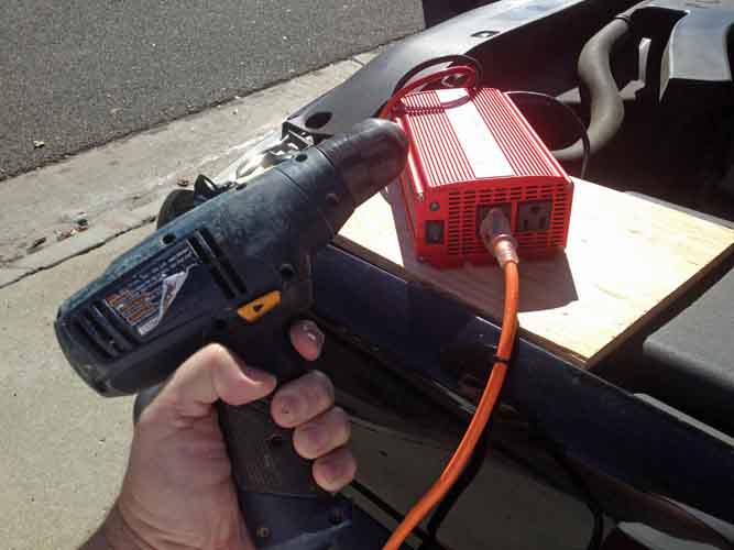
Basically the power comes in the box and goes to the marine rotary switch and the feeder line to the fuse panel is always hot (on the same terminal post), as long as the Aux battery connection is on. The marine rotary switch then controls power to both the 1000W inverter and to the future rear bumper connector.
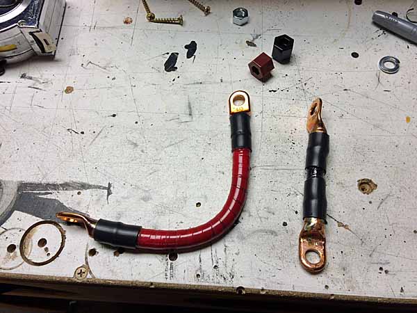
Visible in the bottom of the box is another standalone terminal bolt, for the major ground lines. The studs in the bus bar are the same size, but the routing is problematic for such a confined space and thick stiff cable.
When it's done, I expect to have enough slack and range of motion to be able to plug or unplug the andersen coupling and remove the box if desired.
The space on the right / forward half of the Module lid is for a future likely solar charge controller. I'm considering a bus and feeder line that will charge those smaller batteries from both the vehicle alternator and from solar, with a diode on the vehicle line to prevent drain from these smaller batteries by the vehicle or winching operations. And likewise a diode on the feeder line to the fuse panel, which the small batteries will also power. Thus isolating the added small SLA batteries from major drains. While allowing them to be charged from both solar AND the vehicle. And I have to figure just where to tie in the solar controller so it also tops off my Aux battery. Have to draw out that logic diagram still, haven't thought it all the way through.
My intention remains to be able to power just about anything at all, both inside and outside the vehicle.
I'll also likely in the future get a much larger inverter and fit it with an andersen coupling so I can power heavier tools if necessary.
What I really need to do is the electrical math to figure how much drain at what ratings I can sustain and for how long, with the vehicle off and with it running and with and without solar feed. Doesn't do me much good to power a table saw in the middle of nowhere if I can only do it for 5mins. But I guess that's what a 2kW+ generator is for.
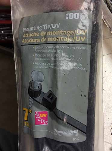
eta I expect to measure my heavy cabling run with standard household wire, then cut my heavy cable to match with a few feet extra. Then I intend to feed the cable into the conduit and then route / wrestle things into place under the vehicle. I'll anchor the rear end with the bulkhead fittings and solder the andersen lugs on the cables and mount the connector. That will 'fix' the orientation of the cabling so I'm not fighting that later. Then I'll get teh cabling runs under the vehicle and up into the narrow gap between front wheel well tub and firewall, rising up to the aux battery location near the existing cabling and charging solenoid. I want the conduit up somewhere between frame rail and bottom of the battery tray. I'll seal the conduit ends to the cables in them, to prevent water intrusion. Then the cables will continue their rise to their terminating connections on the Aux battery. I'll use conduit clamps and self-tapping metal screws to affix the conduit runs to the vehicle frame. I'll probably zip-tie them first as I go, for a rough/ quick attachment, until I'm sure of their locations, then bolt them down.
8000

