Designing a complicated power infrastructure, seeking inputs on my inputs and ouputs

There is no gotcha for oversized power cables. More is better even if you dont pull big power thru the cable. The caveats are weight, cost, and space used...

BTW, you can estimate cable size by referring to wire size/load charts. Remember to add together both legs (÷ and -) of each wire run as the total wire length for that wire run's load requirement... :)

Sent from my Z970 using Tapatalk
 

rayra

Expedition Leader
Did some work today on the rear camera setup. Did some test fittings and parts and radio manual inspection, to see what extra parts I might need.
The camera itself has a thin lead. I'll make some modifications to my license plate, bumper plastic top cover, cargo opening pinch weld and completely route that wire out of sight and more protected. Photo shows the rough reach of the camera lead. That whole area is under the cargo area threshhold, which is laying in the background of the picture with the brass-colored clips on it.

rearcamera07.jpg


The full size RCA jacks are in the washed out bright light patch in the photo. Yellow AV / Video signal connector, and a red for the power.
The vid lead is ~21' long and has sufficient slack for the entire routing to the dash-mounted stereo/DVD/Display. Don't have to buy an extension. I've found 18' radio antenna coax to be JUST long enough, would prefer longer.
The camera kit also comes with a wiring loom for tapping the rear backup light for operating power. The camera only requires a small fraction of an amp. Thus the camera comes on whenever you are in reverse.

If I understand it correctly, my Pioneer receiver unit will auto-sense and switch its display to the rear camera when a signal is detected.

I've fit 6 switches in my dash console, in the bottom right area where the analog On-Star button was. There's a cupholder there in older GM trucks. I intend to wire one of those switches to provide manual power to the camera, so I can turn it on whenever I want, say for reading the plate of a tailgater.
I'll be wiring both the backup light and dash switch power lines with diodes so neither source will backfeed the other. That way I won't be turning on my backup lights.
But now that I type that, that might not be a bad idea, to illuminate things for the camera. But I'm also planning to do the Z-71 roof rack backup / area light mod to my vehicle in the future as well. So if I do need more light, there will be plenty of it.


I also did some slight modification to the plastic mounting bracket of the camera. I think it's designed to fit both USA and euro-style plate mounting bolts, it had very long slots. Those slots greatly obscure the registration stickers on my CA plate, in their proscribed positions.
So I went ahead and cut down the mount tabs into an open fork sort of thing, rounded and sanded the corners. shortening them a good bit so they wont obscure my tags.

rearcamera-5.jpg
rearcamera06.jpg


This weekend I'm pulling the driver side cargo panel to start the preparatory work for my main power cable installs, cuttign down the subwoofer box, fabricate the Anderson power connector mount, cut the access hole in the cargo trim panel and the matching hole in my Power Module, and get under the vehicle to test fit and size my power cable conduits. I'll temp-ziptie them in place, pre-drill the mounting holes for my conduit clamps, verify my floor penetrations for the cable routing.
Next week / weekend, weather permitting, I will finally run my power cabling and my rear Power Module goes 'hot'.
 
Last edited:

rayra

Expedition Leader
A lot of partial progress today.

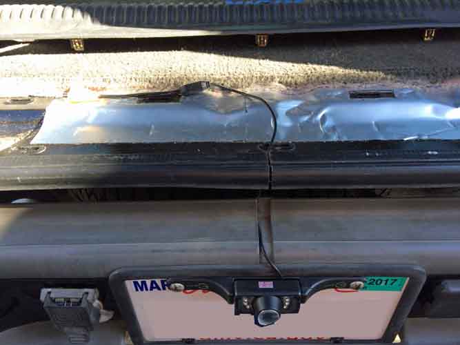
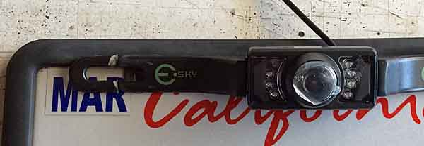
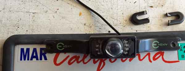
I pulled apart the driver side of the cargo area, in what started out as a final planning on the main power run and the backup camera install. Turned into a partial install / fitting of the empty conduits instead.

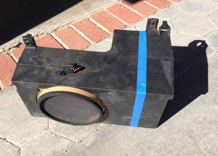
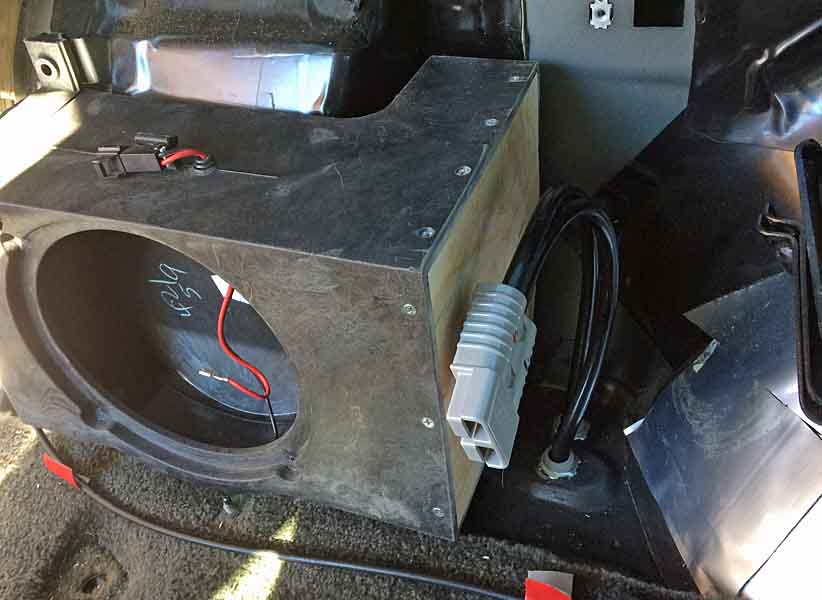
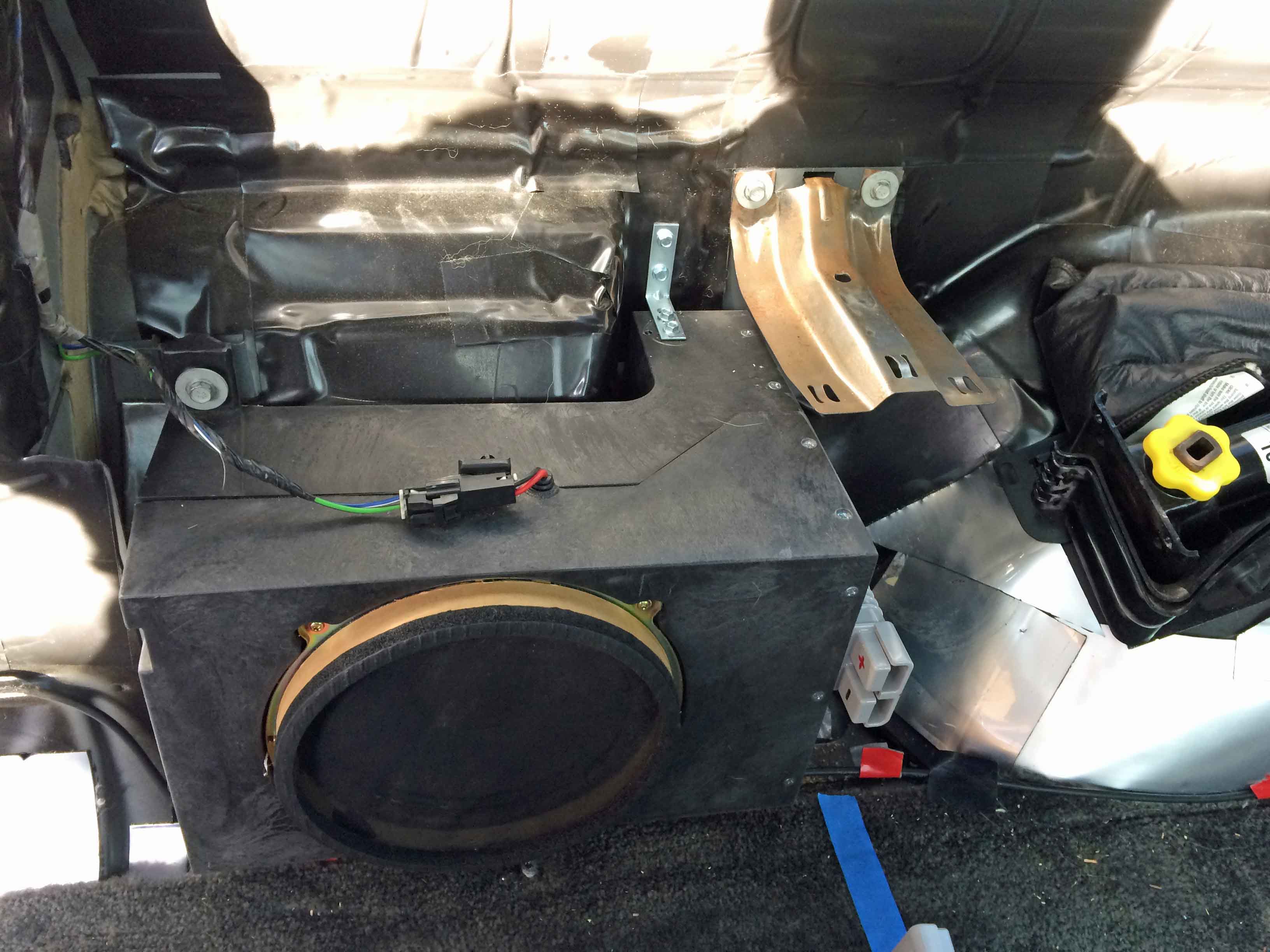
First I pulled out the factory subwoofer box (found my speaker cone degenerated, falling apart, and the large portion of the resonator chamber was stuffed with chunks of carpet foam, apparently from the factory, didn't seem like the box was ever apart.

powermodule139.jpg


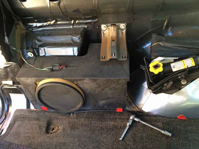
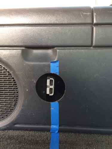
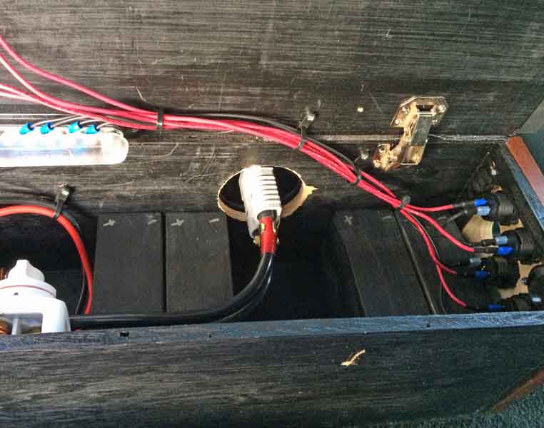
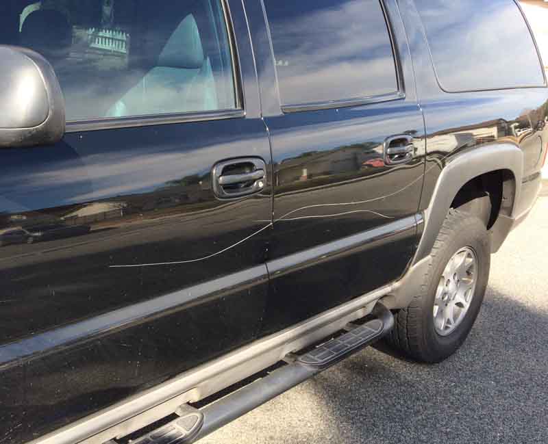
I then re-examined the area where I intended to make my cable penetrations. I'm planning for 4 locations but only using two, intending a future expansion with a rear hitch extension of the main power feeds for a rear winch mount connection. I tried a couple layouts, considering the clearances underneath, the conduit routings, and relative inflexibility of the cabling and the tight bends it will have to make so I can mount the Anderson couplers to the end of the subwoofer box. And also figuring which arrangement will let me butcher the box in a way to make room for everything, but still keep it sturdy. I'm going with the latter L-shaped arrangement of conduit connections as it lets me retain more of the subwoofer box and retain the mounting hardware of the box on that end.

powermodule140.jpg
powermodule141.jpg
powermodule142.jpg


I'm likely cutting on the left edge of the blue tape. I might retain the top surface and its mounting bracket. By coincidence the subwoofer box and my cargo deck height are almost the same. So the mounting location of the power coupling will be a few inches down and not impacted by keeping the top edge of the subwoofer box.

powermodule145.jpg


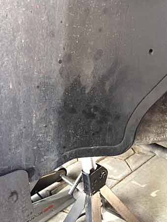
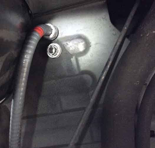
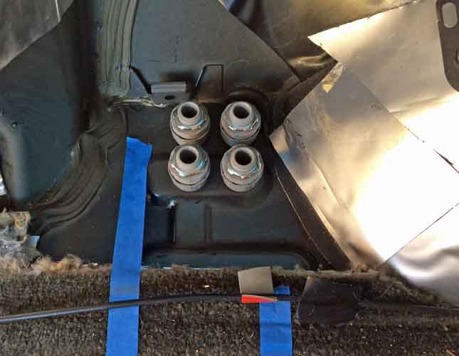
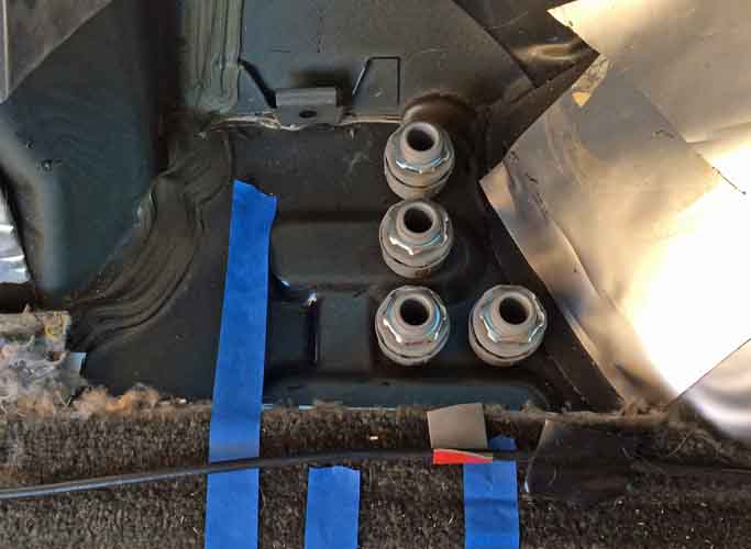
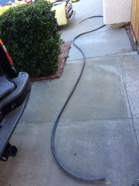
Then I went ahead and drilled my first pair of holes and got the conduit compression / bulkhead fittings installed. Then got my conduit laid out in the sun and bundled it together with twist ties. Not strictly necessary, but it seemed to help emulate the rigidity of having the cable inside it, which will be a factor in my routing of the conduit under the vehicle.

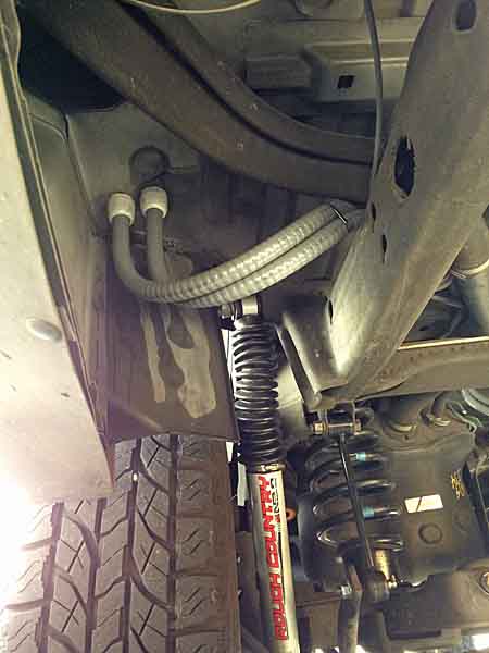
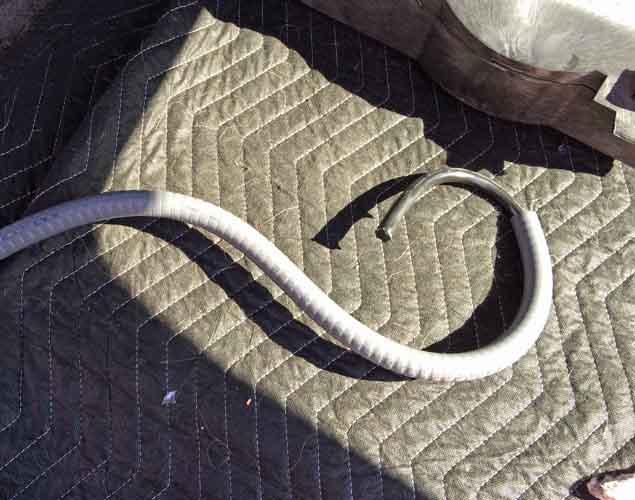
I also took a couple 4' sections of conduit, with scrap sections of 1/0 cabling inside it and bundled them up to use as test fittings to figure my routings. A lot easier that screwing around with 25'+ of paired conduit. I also wanted to see just how sharp a radius I could bend it into. The ends at the floor penetrations are going to have to dip like a plumbing P-trap. It's far too tight a turn to make as a 90deg bend. And likewise at the front where the cabling run turns up from the frame up inside the wheel well to the area of the aux battery location.

powermodule143.jpg
powermodule144.jpg
powermodule146.jpg


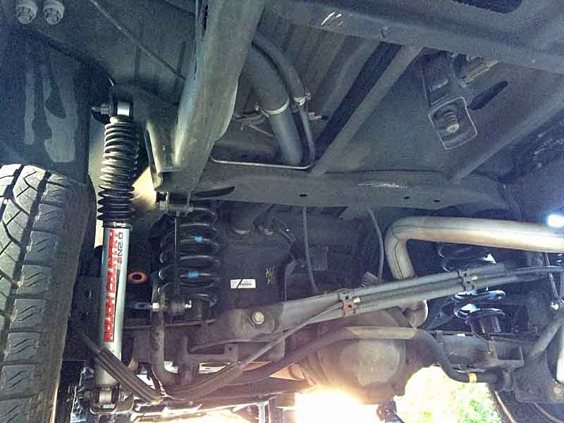
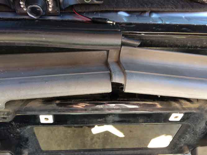
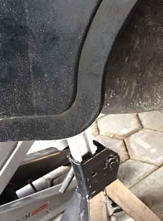
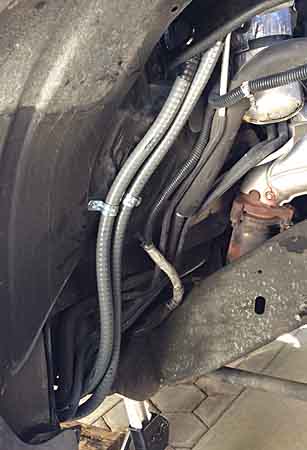
I dropped my spare and made a study of the space and clearances available. My original intent was to go straight across from the floor penetrations, over the spare, then turn up the passenger frame rail. But the spot where I wanted to make that turn, above the forward end of the trailing arm is right adjacent to the rear end of the muffler. So I explored a bit and found a suitable route diagonally across the cargo floor and high over that end of the muffler, clearing it by about 5" plus, and just outside the edge of the factory floor heat shielding.
Should be fine. Only some worst case driving / idling in extreme heat would be of any concern. Will see how it does this summer and if I see any discoloration or blistering of the conduit I'll blind-rivet a sheet metal extension of the heat shield to protect that section of conduit.

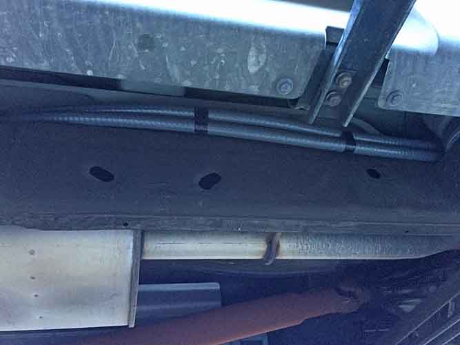
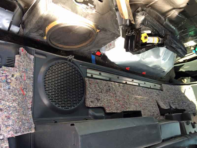
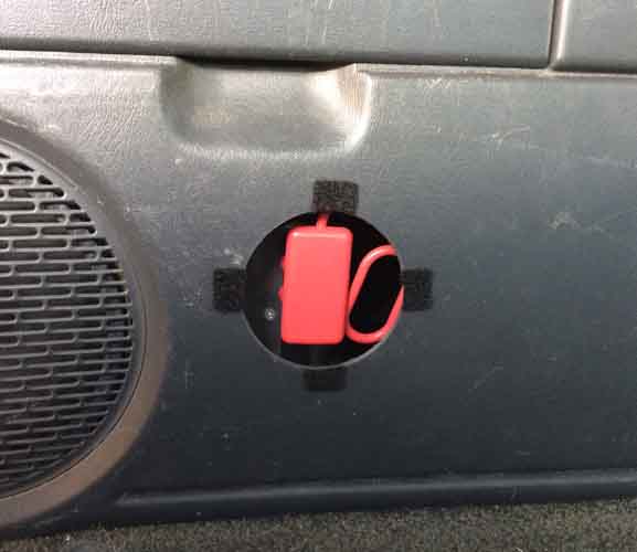
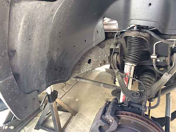
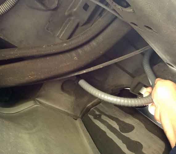
In the top left corner of this image you can see the two conduit compression couplers installed in the floor.

powermodule147.jpg
powermodule148.jpg
powermodule149.jpg
powermodule150.jpg


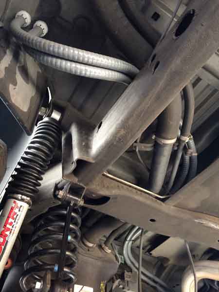
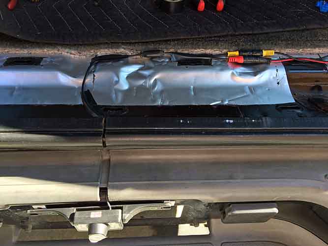
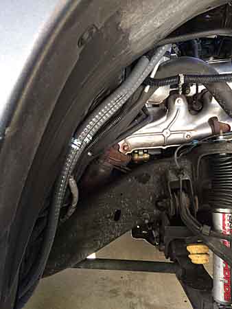
Then I made a few more test fittings along the passenger side frame rail, workign from rear to front, , tucking in and over / behind the body mount sponsons / frame horns, all the way up to where the front arc of the front wheel well.

powermodule151.jpg
powermodule152.jpg
powermodule153.jpg


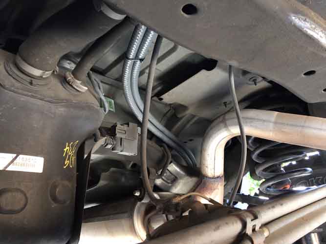
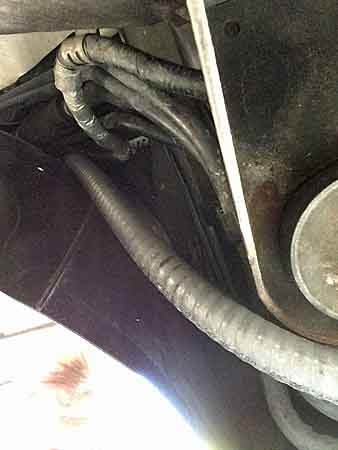
Then when I got to that front point there's a very narrow restriction, cluttered with the rear AC lines and control wiring and an immediate sharp turn upward between the firewall and the wheel well tub / liner. I found it easier to separate the conduits and work them around individually.

powermodule154.jpg


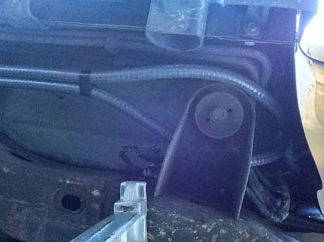
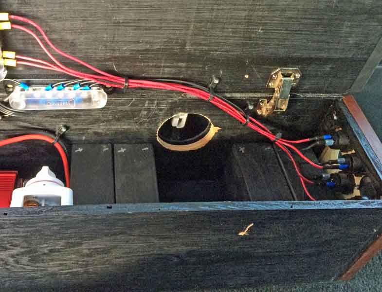
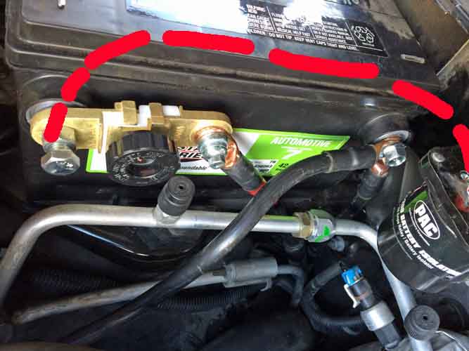
My intention is to have the conduit rise up into the engine compartment, to about the level of the aux battery tray. From there measure the distances to my battery terminals. When I do the final install I'll solder the terminal lugs on those ends, pre-run my cable in the conduits, set those distances and seal and tape the cable in the conduits to close that end against moisture / flooding. Then I will clamp those terminal lugs to the adjacent rigid AC plumbing to their orientation remains correct and then route and clamp the rest of my cable/conduit install. Winding up with a few feet of cable protruding out of the floor in the cargo area. Then I'll size and cut the cable to a good length and sete up a suitable soldering jig in the back of the vehicle to orient the anderson connector lugs properly. There just isn't going to be much give or twist or play in this cable once things are rigged. If the lugs are oriented incorrectly there's going to be a lot of twisting load on the end connectors.

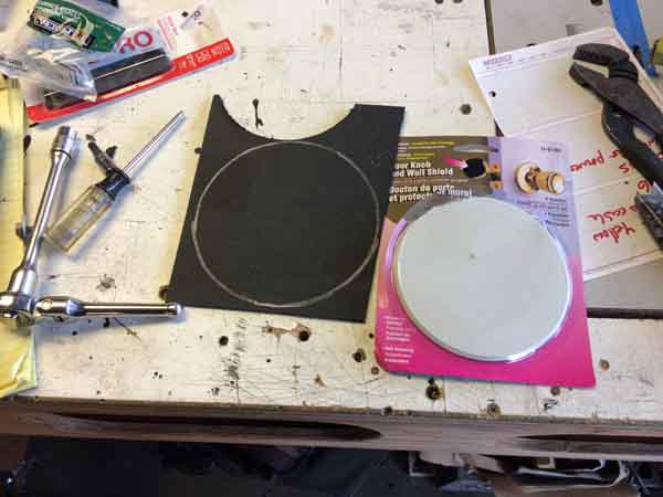
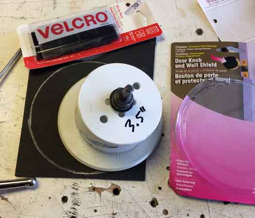
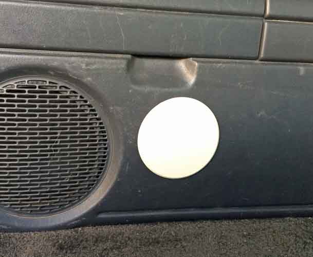
I started fitting the empty conduits last thing today and ran out of daylight and relative warmth. Tomorrow I'll finish up that sizing and cut the conduits to desired length. I'll also drill the conduit clamp mounting locations. Before it gets any later tonight I'm going to go see about chopping up that subwoofer box. And get a pattern made for a wood plank end plug to close it back up and be the mounting surface for the Anderson connector.


9909
 
Last edited:

rayra

Expedition Leader
Bunch more work today. I spent a good bit of time workign on shaping the subwoofer box, using my air saw to trim off more portions of the box, using artful curves to try to prevent stress cracks from spawning from cut inside corners. All so I could retain the top tight mounting bolt location, as I wanted the box as sturdy as possible / original, so I can mount the power cable connector and bracket to teh subwoofer box.
And after all that the box slid off the pile of junk on my work table and fell right on the mounting tab I was working to keep and busted it off in two pieces.
So I went ahead and cut the 'artfully shaped' portion right off. Cut the whole end of the box square and fitted a 3/4" thick piece of planking to fill in the end and form the mounting location for the power connector.

here's an approximation, dummy cables, loose plug. It will be affixed about 2/3 the way up that wood surface.

powermodule160.jpg


Then I finished wrasslin' the conduit into a close approximation of its install location. I really overestimated the needed lengths. When I was guesstimating the layout I was padding each section as a safety margin, would hate to come up short. I was also originally planning to run at right angles, across the frame then up the side, but the rear suspension and muffler / exhaust precluded that and the new routing is essentially diagonal from teh bulkhead fittings to several inches forward of the right rear fender opening, so that saves a few feet of run.
Altogether, I wound up with a third too much. The total conduit run from aux battery tray to rear bulkhead fittings comes out to a tad over 15' with a good bit of slack / broad curves, to better accommodate a clear path and avoid heat sources and exposure to road debris.

powermodule157.jpg
powermodule158.jpg


This portion of the conduit routing is hanging lower down from the future clamped location. It will be tight to the ceiling / floor and away from the sharp edges of the heat shields. And as far up and away from the muffler as possible.

powermodule159.jpg


I'm painting the end of the sub box now and will simply add an angle bracket to that top surface to make good the loss of the factory bracket. It's pretty sturdy without, certainly good enough for normal use. But I want it really bolted down for future couplings / uncouplings of that power connector. That's why I tried so hard to retain the factory mounting when I realized I had to cut the box down to make my overall plan work.

Later this week I'll procure my power cable and fabricate the mounting place for my power coupling, then I can get things installed. Then proceed with the thru-holes in the body trim panel and Power Module box and the other interrelated mods I'm doing in the cargo area.


9975
 
Last edited:

rayra

Expedition Leader
Today it was work making the cargo area cutouts for the power connection.

Here's the subwoofer reinstalled with an added bracket to replace the lost one. The Anderson connector is screwed directly into the wood end panel of the subwoofer. It's all very solidly mounted.

powermodule161.jpg


I would have liked to mount the plug lower down, but don't think I can get that kind of tight curves out of the cabling run, not in that tight space after the cable is in place.


And it was just as well, as the interior trim panel has some metal reinforcement along the bottom that would preclude getting much lower.

powermodule162.jpg


I was planning to make a cover plate of sorts for the hole in the trim panel out of some textured plastic I had, then while browsing the hardware aisle I spotted the wall protector plate (for doorknobs) that was the very size I wanted. So I just went with that. I'm attaching it to the trim panel with velcro. It's 5" in dia., covering a 3.5" hole.

powermodule163.jpg
powermodule164.jpg


And after a bunch of fiddling around with tapes and framing / speed squares figuring alignments, I went for it.

powermodule165.jpg


Looks well centered, doesn't it? NOT what I was aiming for. I wanted the hole centered on a future PAIR of couplings. But this will do for now. But my mind is already working on a future charge port inset panel, like a forklift or RV shore power port. Should have done that from the start.


Here's the Anderson silicone rubber safety cover, which I'd use whenever I have the Power Module disconnected. And the velcro in place and the cover plate. My vinyl dye rattle can was long dead so went ahead and painted the cover plate satin black. Maybe I'll paint it charcoal gray later, if I don't change things altogether.

powermodule165.jpg
powermodule166.jpg
powermodule167.jpg


Then it was a bunch more fiddling with tape, registration marks, measuring tools, trying to make a matching hole in the Power Module box. Which I managed to do, pretty much dead on.

powermodule168.jpg


An approximation of how things will fit. The Power Module connector will go about 1/2" deeper into that hole. And my four mockup 10Ah scooter batteries still work out fine.

powermodule169.jpg


I'm already thinking about some sort of 'junction box' enclosure around that plug behind the body panel as well as an annular gasket between the Power Module box and the trim panel, all for potential spark control. Worst comes to worst, my extinguisher is right in the front of the adjacent cargo platform drawer, and the top tray of that trim panel lifts right out for access to the jack. I can hose that confined space.


10,040
 
Last edited:

MagicMtnDan

2020 JT Rubicon Launch Edition & 2021 F350 6.7L
You had me at "Heathkit"

I need to come by and check out your Sub and your electrical system and your woodworking.
 

rayra

Expedition Leader
Sure, one of these days. Not much woodworking going on lately. But have some stuff lined up for the Spring.


Today was a bit of a detour, spent a couple hours work fiddling around to get my backup camera installed, while I wait on Amazon and continue shopping for my last run of 1/0 cable.

Straightforward install, decided not to do the 'extras' today as I need to do some related other stuff first. So no additional switch / wiring to make the camera hot whenever I want.

I'll also have to review the Pioneer dash unit manual again, as I had the impression the camera visual would appear automatically whenever its signal was detected. As it stands now I have to manually switch to it. But that's just two touches on screen, after putting the vehicle in reverse.
Maybe a better thing to do is wire the camera to the stereo power source so the camera is always hot when the key is on.
Anyway, more options to explore.

The camera image itself seems adequate, got a good image looking back into my shaded garage.

Decided to forego for now drilling clearance notches in my plate frame, license plate to fully hide the wiring. But did notch the plastic bumper cover to pass the wire under it, on the way to entering the cargo opening.

backupcamera05.jpg


I took advantage of the existing butt-joint of the Liftgate opening gasket. I notched the pinch weld under it adn used a bulkhead grommet to pass the camera wiring inside, then just put the Liftgate opening gasket back in place.

backupcamera06.jpg


backupcamera07.jpg


I'll try some images 'in the wild' in coming days and see how easy or cumbersome it is to switch the camera view on while in the midst of backing.

The one other thing I particularly like with the license plate location is that it will make hooking up trailers a breeze. The camera head can be pivoted up/down slightly, so I can aim to perfectly frame an attached hitch ball.

I'm hoping to do my major cable runs this weekend or next. I think I have everything figured out now.
 
Last edited:

Bear in NM

Adventurer
I have the Pioneer Nex4100 and my backup camera will automatically come on in reverse. I can also press a couple of buttons and have it fire up while moving, which is very handy for taking a peek at my trailer while under way. I think I tied into my parking brake to bypass being stationary while playing a dvd. Although that is not something I do. Take a look at your manual, and perhaps do a little web crawling against your model number, to see what it will do.

In having the backup camera for a year and half now, I have certainly formed some opinions. Not sure whether you have better or worse view out the back than my Avalanche, but the camera is great, coming on automatically. But, I have found that if I try and just use the camera as an aid to actually looking out the back and using mirrors, things are more dangerous for me. Probably all of the brain gyrations of seeing left and right, then looking down at the screen, then repeating. i have found that I am much safer if I just use the camera, and focus on just that. If I back with mirrors and looking, I try and just do that, perhaps looking at the camera if trying to see the distance to something low, behind my tailgate.

Certainly hooking a trailer is stupid easy now. But having to fiddle with the stereo screen to have backup view would be a pain in the rear. The additional installation of your system looks great. And I am jealous, as the weather in my locale has pretty much meant no vehicle exterior work for a few more months of snow and mud.

Craig
 

rayra

Expedition Leader
It was over 70 and sunny, yesterday. Lovely day for such work.

I found the other section in the manual last night and I'm re-wiring things today. There's a violet-white signal input wire on my unit, that should have been connected to the reverse light. And I fould a good suggestion online last night suggesting hooking the camera to the 7-pin wiring instead for both power and ground. Thus the camera is always hot when the key is on and whenever I put it in reverse my unit will auto switch. And the camera will work whenever desired, manually.
And since I've previously relocated that 7-pin connector into my bumper next to the license plate, it will be a very short run to wire things up. Just annoyed I'm going to have to pull the interior apart again to route the new signal wire. Probably take me 2hrs to re-do things.


eta

Took about what I thought. Spliced into the trailer coupler for power (red) and ground (white) and ran a new signal wire from rear backup bulb to camera he stereo connection. I tried to pick up that backup wire in the thick bundle of 35? 36? Wires in the passenger side door track, but all the same green wires were all hot with key on, not in reverse.
I've got a bunch more dash and console wiring to do in the future for radios and light switches so this time I half-assed the wire routing. I have to open it all up in a couple months anyway.

backupcamera08.jpg
backupcamera09.jpg


So everything works as desired now. Display auto-switches to rear camera view when I put the vehicle in reverse and at any other time with key on I can call up the rear camera view.

I'm REALLY liking modern head unit tech. This Pioneer AVH-280BT does damned near everything. Stereo, DVD/DIVX/MP4/MP3 playback, aux mini-din input cable, USB input cable, camera AV input and display, AV output for back seat displays, blue tooth connectivity with phone integration of addy book and microphone input. And I added an aftermarket bit to fool the Park sensor and allow video playback in the dash while I'm moving. All of that for about $300, including the (cheap) camera, doing all the install stuff myself. whoops add about another $50 in junkyard and adapter kit parts, for making a double-DIN stereo work in the DIN-and-a-Half dash of the 2000-2002 GMT800 trucks.
 
Last edited:

Bear in NM

Adventurer
Cool, looks good and glad you got the stereo sorted out. I know for lots of folks, having a large display and all the av goodies is old hat, I came from a 91 Wrangler, and my Toyota work only has a radio/cassette. My Pioneer does everything yours does, and I have it set up with remote plugs for just about anything anyone would want to plug in. When I did my din and half to double, and installed everything, I am sure I had my dash apart at least 20 times getting everything perfect. I'll have more to do this summer, when I get new speakers, and sort out some shielding I need for my anderson connectors in my cubby hole mount, that have fouled my AM reception.

My Pioneer also has a slot for micro sd cards, and it sure is nice to have all of my music ready to go, all the time. My biggest headache in doing all of it was probably the amp bypass. That puppy is tucked up high and tight, and was a pain in the neck. Unlike mechanical mods to my truck, I actually like the stereo and aux 12 volt stuff. Not near as back-breaking......

Craig
 

rayra

Expedition Leader
Yep. Is yours a newer series, or is the Nav-equipped line?
The only difficult parts are integrating with these highly-computerized vehicles and getting your hands and wires where they need to go.
I'm looking forward to replacing my former defunct 4:3 fold-down ceiling LCD display and putting in a newer HD(-ratio) screen. Right now I hvae its large baseplate still on my ceiling as it covers the large hole they cut in the headliner during that install (prior to my ownership). There's a remote control unit offered for my stereo, it would go well with the ceiling display for camping / sleeping in the back. Or even going RV-style with the exterior TV. That would be a cool thing to add, glamping-wise.
 

Bear in NM

Adventurer
I bought mine a year and a half ago, so I guess it is fairly new. No nav on the unit, but as it will mirror my phone screen I could nav that way. But I am a Garmin user from back in the dark ages of navigation. And as I frequently use my Garmin for work, I decided a good handheld was in order last year. I now have a Montana and a Monterra. I have a cradle set up on my dash, attached to the A pillar. I find that having the screen closer to eye level is easier to navigate, as my eyes only have to look down just a tad. And as the unit also gets used handheld and now on my little motorcycle, a portable nav works well for me. I live in a small town, and never need to use navigation like folks in real places. I did get to use it in Las vegas at Christmas, and it does work to do the mainstream like Starbucks and malls ;^)

My Pioneer came with a remote, but it sits in my console box. I don't really camp with AV per se, just using a Jawbone speaker for music. But, I could see the integration with more Av stuff would be cool. Especially with a Suburban. For truck camping in my Avalanche, I set up my bed tent and open the mid-gate, so I do have an open area much like a Suburban. Surround sound and a ceiling screen would be a little tougher for me. Don't be giving me ideas......

Craig
 

rayra

Expedition Leader
yeah, I like the screens up high as well, been using a suction cup mount for my iPhone, at the top edge of the windshield just left of the rear view and dash cam.
I also fabricated a dash-top mount for a 7" android table, it rides right above the dash unit's display. Been farting around with a couple topo-/nav- apps in that and it looks quite promising. And the location is ideal for me. None of the stuff blocks my forward vision like the rear view mirror does, anyway.

http://forum.expeditionportal.com/t...ablet-GPS-mounts-please?p=2075866#post2075866

Things have changed since this photo, now the iphone and dash cam are more in a sort of 'eschelon' formation with the rear view. The dash cam bottom is higher than the bottom of the mirror. But you can see the tablet over the Pioneer screen. I like the way they align. are a near match in size.

tower%20of%20power.jpg


/that reminds me, I need to increase my auto insurance coverages lol
 
Last edited:

rayra

Expedition Leader
[Jaws intro theme]

powermodule170.jpg


Going for it tomorrow, weather should be prime


10,616
 
Last edited:

rayra

Expedition Leader
Went out about 10am raring to go, a beautiful day. And found this. Not even a week since the drug dealers moved back in next door.

keyed.jpg


After screwing around at the Sheriff station reporting the felony vandalism, getting a report number, calling USAA and shopping for a short run of welding cable, it was 2pm before I got started.

Had to go out to shop for some welding cable and lunch, so I went by the Sheriff station to make a report and get a report number for USAA. It's felony vandalism. I was surprised to find out the price plateau for that is a mere $400. I'd thought $1k was the threshold for a Felony.


Work ran well after dark with a headlamp. Not finished, but both ends are hooked up and things are zip-tied in place so the vehicle can be driven if necessary. If there's a break in the rain tomorrow, I'll work on soldering the rear connector plug and get things tested. This weekend I'll get the conduit clamps installed underneath and tidy up the cable / conduit routing.

The front end of my conduits are open, I wanted to caulk and tape them up, with a calculated amount of my cable runs exposed. But I had to use cable lube to shove 18' of 1/0 cable thru 15' of 1/2" conduit. So much for caulking, no good way to get the lube off / out. So instead I wrapped the cables in electrical tape, sufficient to make a plug. Then wedged that plug (peeling a winding or two off to make it fit snug) into the conduit opening to plug it. Then thoroughly taping up that union. The other end of the conduit goes in the bulkhead compression fittings in the rear cargo area floor.

powermodule171.jpg
powermodule172.jpg
powermodule173.jpg


I once again used a couple empty conduit sections as feeders / guides for routing my cables up the fender well and to the aux battery area. I did this by bundling the empty sections together and shoving them down the narrow gap between wheel tub and firewall, from above. Then I fed the bare terminal ends of my prepped cables into the empty sections and shoved it all back up the gap. The empty sections act like guides / protectors for the factory wiring looks, AC lines, and the very sharp edges of the aux battery tray, while the cables are routed into place.

When it was done I had me new cables sticking up roughly where I wanted them.

powermodule174.jpg


Then it was time for some wrasslin' and twisting. Despite trying to straighten the stiff coiled 1/0 cable, it still have a bit of a curve / twist to it. This was compounded by the curves and turns of installing the front portions. The terminal lugs wound up out of plane with the battery side terminals, by about 20-30 degrees in opposite directions. So I had to work hard to twist and the whole cable run to get the battery ends aligned closely. I wanted no rotational torque on the battery terminals. Especially from this stiff cable. Not forgiving at all.

Once I got the lugs aligned correctly I worked things up and down and did my hand-bending of the cables to get the connection alignments I wanted. I removed the short straight run from my dual battery setup / isolator to the Aux POS terminal. It's position totally interfered with my intended rotary cutoff switch for the power run to the rear. I'll make a new / replacement isolator->Aux POs cable that has a J-bend in it to pass above and clear of the rotary cutoff, keep that accessible.
I have two negative cables on that aux post. The run to the rear, vertical, right down the firewall; and the ground to frame connection. I passed it over the other side of the AC line.

powermodule175.jpg


And my new power line to the rear is positioned so the rotary switch is installed in a horizontal line

powermodule175.jpg


And the new line from the solenoid will pass over top

powermodule176.jpg


And a random shot of the POS conduit hooked up.

powermodule177.jpg


No camera work after that, it was getting dark and I was working hard to get things secured enough to drive the vehicle.
Tomorrow, rain or no, I'll get the rear cable ends sized and shaped and get the Anderson terminal lugs solder on them and make the rear connector hot. then I can test my Power Module box and see if can keep the magic smoke from escaping.
 
Last edited:

Forum statistics

Threads
185,891
Messages
2,879,506
Members
225,497
Latest member
WonaWarrior
Top