Designing a complicated power infrastructure, seeking inputs on my inputs and ouputs

rayra

Expedition Leader
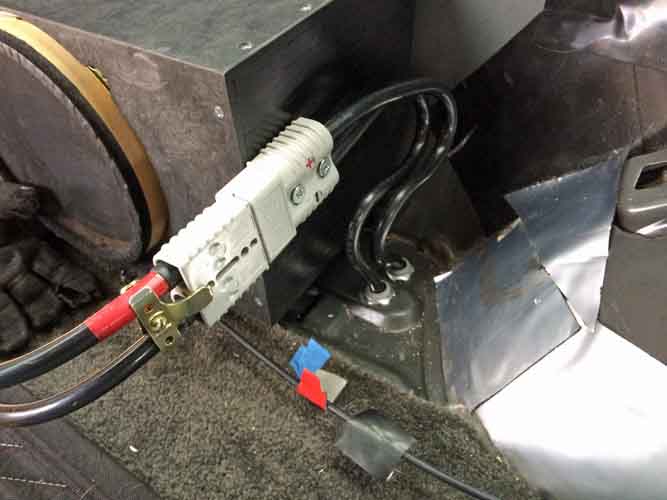
Made up the new solenoid->aux battery connection cable. Routed high and down to the terminal bolt, leaving ample clearance to work the rotary cutoff switch on the cable to the rear. And glopped some 'liquid electrical tape' on the exposed top connections on the solenoid.
powermodule178.jpg


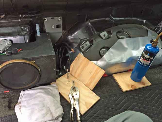
Then it was on to torch-soldering the other ends, inside the back of the vehicle (don' neeeed no stinkin' crimper). Ventilation, wet towel and extinguisher at the ready, all the tools ready for this silly exercise.

powermodule179.jpg


I used the vise grips to hold the anderson terminal connector with its cup up. I filled the cup with cut lengths of solder and did the initial heat / melt on my garage workbench. Then fed more solder into the melt until it filled teh cup about 2/3 the way up. Then carefully moved that molten mess into the vehicle. Got the torch back on the cup, grabbed the already prepared and positioned wire next to the cup and heated both at the same time, then seated the exposed wires fully. Go slow so you don't jet molten solder out. Do it right and the wire eases right in until the insulation makes contact with the lug.
powermodule180.jpg


No spills of molten solder, no torch burning of anything, and only a very light scorch where they tip of the anderson connector touched the plywood underlay.

I did a bunch of manipulating of this stiff cable, to see how much I needed to comfortable align with the connector position. I wanted extra to have the reach for the soldering, but not so much I could stuff the djinni back in the bottle, so to speak. Make the hand bends, rough test fit, re-bend, test fit, unbend it all and shift the curve placements, test fit. Like some kind of circus muscleman strangling horseshoes.
Finally got it sized well enough, committed with the bolt cutters, then did the soldering. All to arrive at this:

powermodule180.jpg
powermodule182.jpg


Now I go to try and find some welding cable by the foot, of some similar battery cable. 2 gauge will work for now, if I can't find 1/0. It's what WARN sells for their rear winch cabling kits, anyway. Get that Power Module coupling rigged and it's done.


10,692
 
Last edited:

rayra

Expedition Leader
"I HAVE NOT MADE FIRE!"


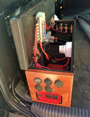
Last night I got the coupler inside the 'Power Module' remade with more flexible thin-strand 1/0 cable, but got totally raped on it $6++/foot. Need the better flexibility for the coupler, the way I have my box contents arranged. And to maintain the ability for a future addition of solar controller and extra batteries.

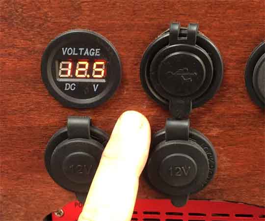
This morning got the power module plugged in and successfully tested everything. All the various power outlets are hot. My rotary cutoffs function with no trouble, the voltmeters work great. All that is left now is to crawl back underneath and finish arranging and securing the conduits/cables.

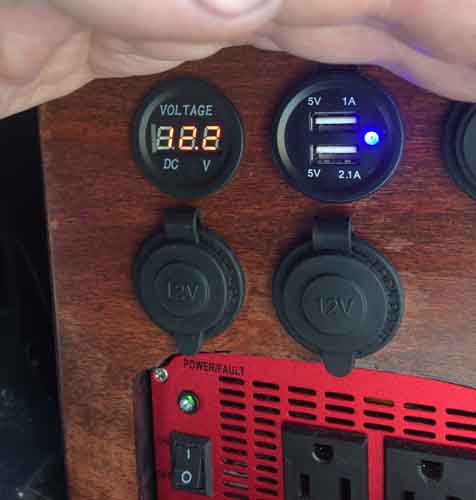
Basic connection and power up, the voltmeter showing the Aux battery is a little low. Been disconnected for a while.

powermodule183.jpg
powermodule184.jpg


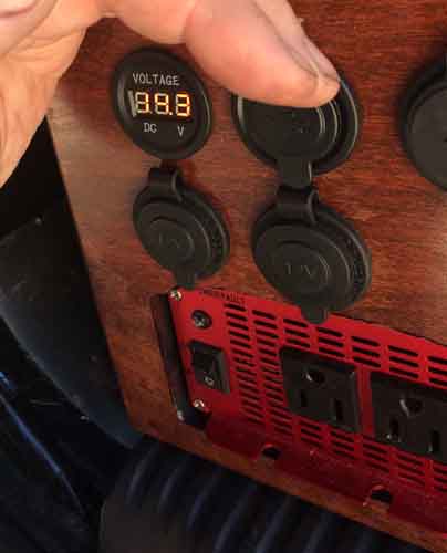
And showing 14.3V with everything coupled and the vehicle running.

powermodule185.jpg


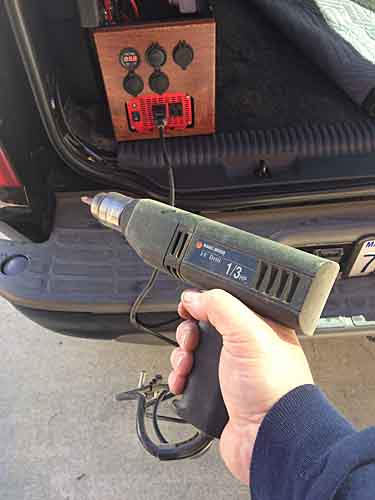
Running a powered drill off the inverter

powermodule186.jpg


So that's about it on the power upgrades for now. The magic smoke has not leaked out.
I'll update later with future upgrades / expansions or usage reports. And if there are any problems in use.


10,784
 
Last edited:

MagicMtnDan

2020 JT Rubicon Launch Edition & 2021 F350 6.7L
Nicely done and explained/demonstrated.

Now you're ready when the DWP throws a brown-out in your area. You can power your house.
 

rayra

Expedition Leader
I might go with a fatter inverter with an APP pigtail on it, for that sort of 'disaster prep'. This inverter is only 1000W. Enough for a few things, light, TV, radio, charging small electronics. But that was part of the whole idea for the 'Power Module'. I want it for glamping, my amateur astronomy hobby, road trips with several passengers and their electronics. I've now got 6 USB ports my dash / console areas besides the 4 I've just added with this power box. And small APPs for HAM radio power, RC hobbies etc. And the 110VAC. I wanted to be able to power and/or charge just about anything at all.

That big thunderstorm cell over our heads just chased me out of the driveway, was trying to make the last clamp installs on the conduit. Guess that has to wait for tomorrow.
 

rayra

Expedition Leader
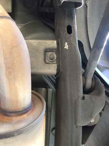
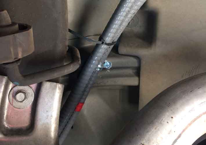
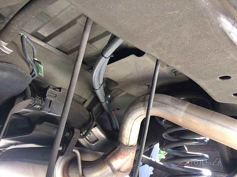
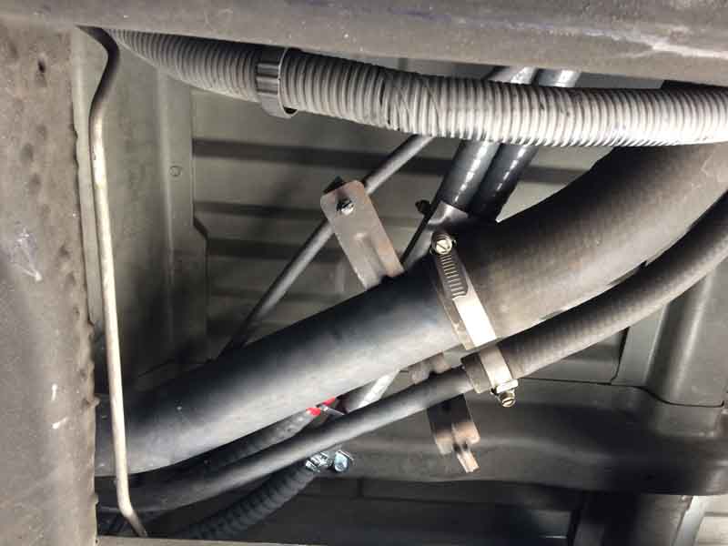
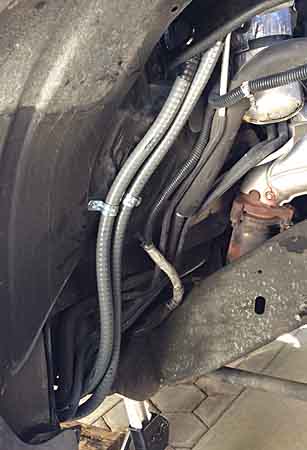
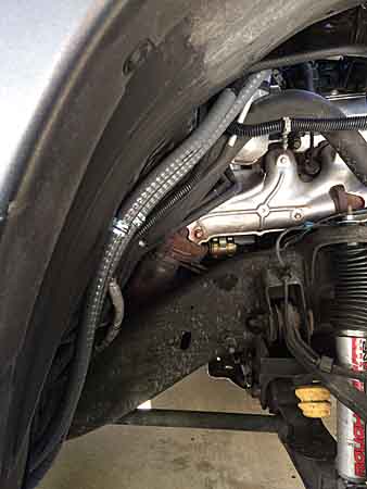
Finished the undercarriage work, tidying up and securing the cable / conduits. A few more cable clamps and self-tapping screws. I picked a few spots in the sheetmetal floor where it was a double layer. I didn't attach to the frame itself.

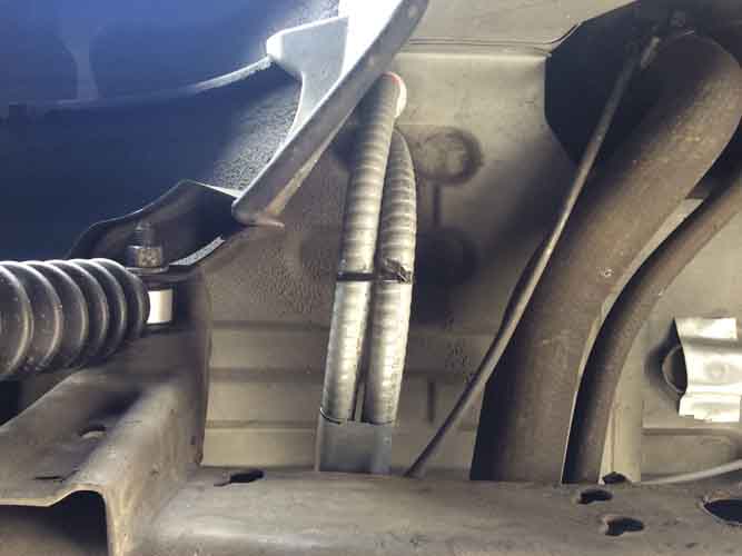
Peekaboo shot where the conduits cross from outboard passenger side over the muffler / exhaust. Physical separation is ~5" and their routing is an area with no heat shield, so very little concern about heating. But will be checking in the summertime.

powermodule187.jpg


The clamp / routing over the tailpipe rearward of the muffler. This is under the cargo floor, near the front of the right rear wheel tub.

powermodule188.jpg


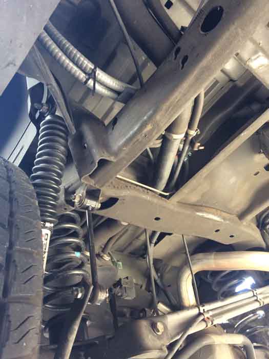
Here's a viewpoint from the spare tire area. Those two taught near vertical hoses are rear brake line and axle vent. That's with just the right rear wheel at max hang. Ungood. Not enough slack.

powermodule189.jpg


This is a shot looking straight up at the ceiling / floor, where the conduits cross above the fuel filler hoses & vent. Mounted and pressed up, the conduits don't touch. But there's enough flex / play that they my touch. So I added a rectangle of peel-and-stick sound mat material to the conduits as a wear guard / witness piece. Will be checking that too. I might add a thick piece of neoprene between them in the future. Don't want any failures from chaffing, especially not where a 1/0 battery cable cross a fuel/air hose.

powermodule190.jpg


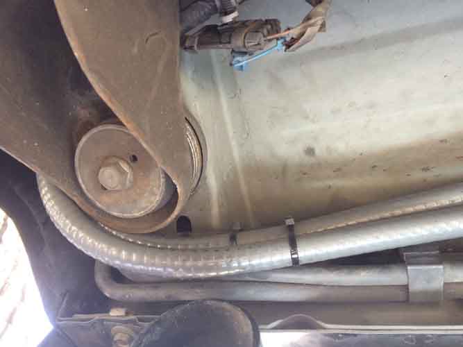
Another shot looking straight up, at the floor penetrations trailing the rear wheel well. And again a piece of sound mat material as a chaffing guard / witness material.

powermodule192.jpg


Here's a wide shot showing all the cargo floor cable routing. The spare winch mechanism is just out of frame, center right.

powermodule191.jpg


Here's the front where the cable / conduits go up between the front wheel well tub and the firewall, to the aux battery. Loose / unformed, they were pushing the plastic wheel tub towards the tire and I was making tire contact under suspension compression. I wrassled / strangled that for a while, working to put a sharper better-shaped bend in the cabling and made a good amount of improvement. But to do a proper job of it I probably need to pull the wheel and tub and really get my hands on the cabling to really shape it. Work for another day. My 'Leonardo's disease' is kicking in and I'm about at the abandonment stage on this project.

powermodule193.jpg


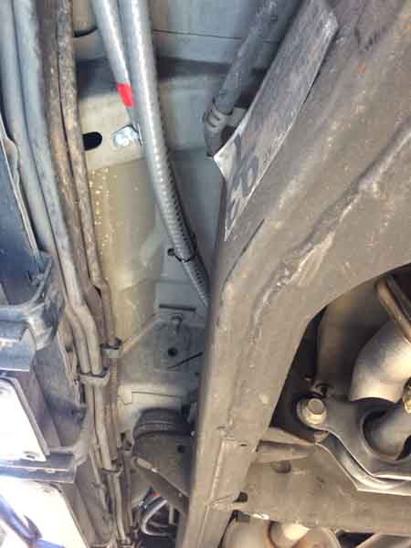
And a long shot looking rearward along the passenger side frame rail.

powermodule194.jpg


That's about it for this project. This initial phase at least. In the future I'll likely be adding some additional smaller batteries, a solar charge controller into the power Module box, and add an external solar panel input and shore power connection on the end of the Module. And a roof rack connector for a roof-mounted solar panel kit. I'll have it arranged so I can be secured flat and operational on the roof, be tilted up on the roof in camp mode OR be dismounted and placed on the ground and plugged into the Module face. Maximum flexibility.

For the 200 or so folks that seem to be following along, thanks for your interest and I hope I provided some useful info for you. See you in my other / future 'building' topics.

Fin-84762.gif


10,860
 
Last edited:

jgaz

Adventurer
Nice job! You put a lot of thought and a TON of effort into all this to realize your vision for this project.
Thanks for taking the time to document your progress.
 

rayra

Expedition Leader

Oh no, guess I better tear it all out and do it again

/f'n lol NON


Now you see it, Now you don't.

powermodule178.jpg
powermodule179.jpg


Added a very small momentary switch in the voltmeter circuit in the Power Module. Hadn't factored parasitic loads in the design, was losing about .1V++ a day from the twin voltmeters and 2x2 USB converters (with status LEDs). I unplugged the front-facing voltmeter, it's obscured by the cargo platform fill-in box anyway. And put the rear facing voltmeter on a momentary. The other idea is just leave the whole box unplugged when not needed, but that takes some of the convenience out of it.
 
Last edited:

rayra

Expedition Leader
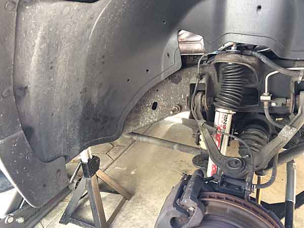
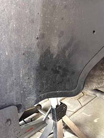
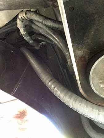
Was having a bit of trouble after my big power cable install, I didn't make a hard enough bed where the cables in conduits transitioned from the firewall to the undercarriage and they wound up pressing the plastic wheel tub / liner towards the tire. Hard right turn, suspension compression, the tire tread was contacting the liner. Terrible racket and possibility of worse damage.

So I figured I needed to pull that liner and find a place to clamp the conduit to the firewall and do so in a way that didn't wind up puncturing my heater core or AC plumbing.

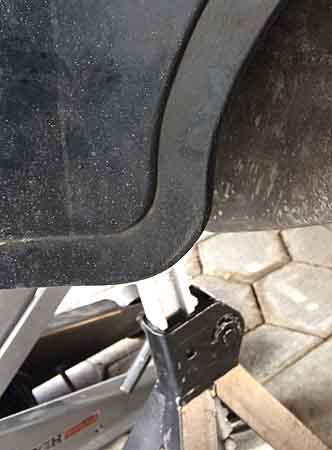
A few pics of the liner, the darker 'clean' area is the point of contact. And a view from the back side showing the conduits pressing against the back side of the liner

powermodule170.jpg
powermodule171.jpg
powermodule172.jpg
powermodule173.jpg


I failed to take an overall pic with the liner out, showing the conduits clearly standing clear of the firewall. But here's the pics after I clamped things down. I pulled upward on the undercarriage slack and pressed the conduit against a spherical indent on the firewall to test the fit and mark a clamp screw location. Then dug around on the interior footwell to assure myself I was clear heat / AC equipment. The location wound up being about where the toes of the passenger would reach, free and clear of critical gear. So I went ahead and drove the short self-tapping screws in. Before things were tight I pulled upward on the conduit / cable to relieve any strain on the battery posts above.

In this pic you can see how the conduits now tuck against the firewall indent. They used to hang / project about as much in the other direction.

powermodule174.jpg


And a shot across the rear plane of the wheel well, showing the tuck

powermodule175.jpg


I put the liner back in, had about 1/2" of clearance from the conduits and no longer making tire contact at full lock.
Just one of those little things / dominoes to deal with, once you start making modifications.


12380

13666 170525
 
Last edited:

rayra

Expedition Leader
another topic rescued from Photobucket's $400 extortion demand.


and a heads-up that Phase II is gearing up. Solar panel integration into the Aux battery circuit. Using a folding / briefcase panel and to include power connections for roof deck mounting, set into the roof rack footing, as well as on the rear face of the power module so the panel can be set up on the ground and connected with a longer cord run.

Panel roof mount will likely include some semi-permanent bracketry with security-head screws, so the panel can stay mounted, passively keeping the aux power at max. This would have come in handy last Friday. We made a 90mi trip across L.A. for an amphitheater event and I mistakenly left a medium-sized peltier cooler/warmer plugged into the factory power port circuit. ~6hrs later when the event was over, the keychain fob alarm / / unlock barely worked, interior lighting was very dim. With the Aux & solenoid I just turned the key and waited a short moment and started the vehicle. In the future I'll be sure to plug the cooler into the rear power module port(s), on the isolated Aux battery. It's why it is there, after all.


Everything else is working fine, as planned and built.

I'm also thinking of mounting a wifi high def night capable security camera in the rear of the vehicle, as part of my home security camera setup. Especially once solar is set up. The cameras are 12VDC native. And where I park is well within reach of my home wifi setup.


Such a setup should also be usable with my iPhone running as a hotspot, displaying the video on the phone. Useful form inside the vehicle with blackout curtains, useful inside a tent.

14275
 

rayra

Expedition Leader
cross posted from another related topic

------------------------

I'm getting 'close enough' out of my disparate pair of auto batteries, which are combined with the key on vi a 200A solenoid arrangement. My 'Aux' is a Grp 74, the Starter is a Grp 78. Both Interstate brand, manf dates a couple months apart. WHen I spot check with a handheld meter my aux is usually about .3 V higher. The Aux is daisy-chained off the positive terminal on the starter battery, rather than attached to the common connection point next to the alternator (little red box on GM / vortec / GMT800 setups).
Not sure if the internal regulator is being fooled somehow by the higher capacity Aux battery, or (more likely) that it's just a reflection of the parasitic drains I have from multiple aftermarket USB power ports with LEDs or the dashcam powered off the overhead courtesy circuit, which keeps running for 10mins after I turn the key off. Which are all on my factory wiring and thus draining the Starter battery.
I'm not driving the vehicle often enough or far / fast enough to keep the batteries topped off.
Individually I can charge them both up to 12.7-12.8, using a craftsman charger plugged into house power. But once back in the vehicle the disparity reappears.

I'll soon be adding a folding panel in a semi-permanent roof mounting and was intending to connect it to my cargo area power module / Aux circuit. But now I'm considering a way to make it switchable and leave it primarily feeding my Starter. Switchign it over to my Aux setup when I'm using that more heavily.
 

rayra

Expedition Leader
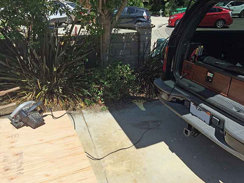
This weekend I gave the inverter a little workout, while installing a water heater and remediating some mold. Had to rebuild the whole corner where the leaking water heater had been. It was literally easier to just plug my circular saw into the inverter.

powermodule195.jpg


also another preview of coming attractions -

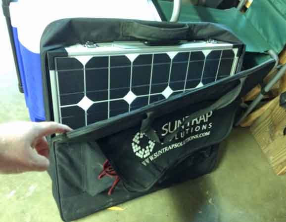
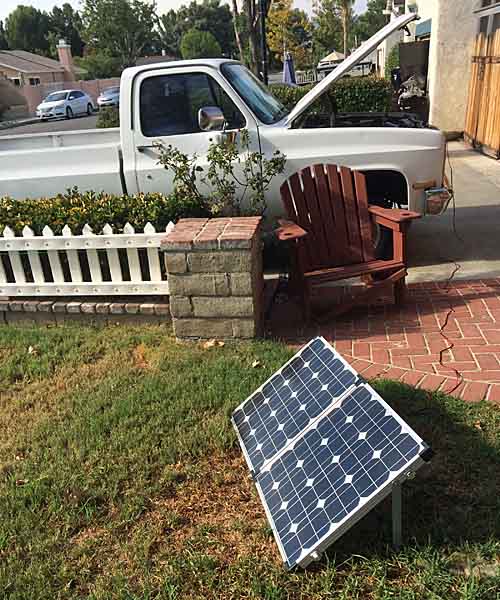
This is the panel I'm going to create a roof rack deck flat mount for. The panel will nestle into a lockable metal frame and be tied into my Aux power setup so it works as a trickle charger all the time, will keep that setup fully charged all the time. And when camped / bugged out, the panel can be more properly deployed for much better efficiency or even ground deployed at a short distance from the vehicle, so the vehicle can be shaded or concealed (awning project ;) ) while the panel is out in the direct sun.

solarportable01.jpg
 

rayra

Expedition Leader
report from another topic, as working notes

----

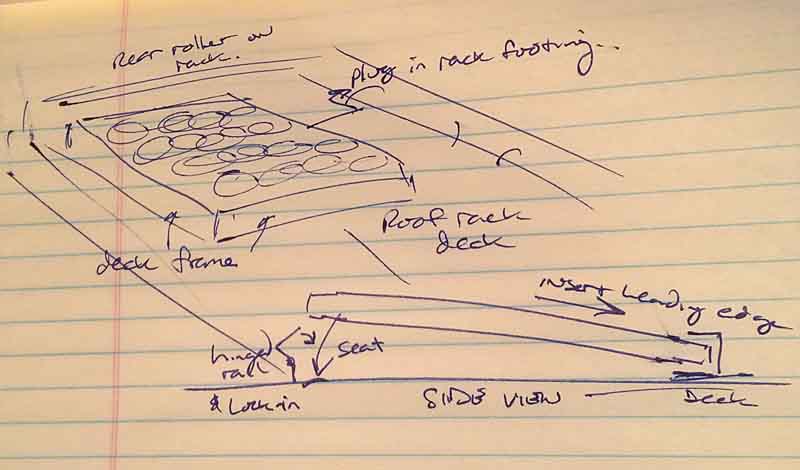
Here's a quick sketch of what I'm planning. A sort of picture frame that will trap the panel in a flat 'stored' mounting on my roof rack deck. Which can be readily unlocked to free the panel adn raise it to the appropriate angle and orientation for max gainzzz. Or even set on the ground on a longer lead. I'm going to wire things so the panel when on the roof will be connected via fixed wiring to my Aux Power Module in the rear of the Sub. And have a second connector on the rear faceplate of tha tmodule for when the panel is ground-mounted.

solarpanelmount01.jpg


eta I'm even toying with the idea of putting most of the mount and panel on a lazy susan so the panel can swing some side to side, locked in the centerline position when it is trapped by the locking plate. And incorporating a subframe with pneumatic lifters and a limiting wire so when you unlock the panel it pops right up to the pre-set optimum angle. And the 'ready' angle for mounting or dismounting the panel.
There's only 44" between the side rails of my rack, so it won't have much of a range of motion.

I'll be developing the idea in my Aux power topic in the 12V forum.
 

rayra

Expedition Leader
solarpanelmount02.jpg


The folding panel has some built in legs, but they are kind of short. Their angle of repose is more suited for peak summer in low latitudes and there is no adjustability in the leg height, except by how far you open them. And all those angles are even worse.
The legs are also made from cut flat sheet metal and have sharpish edges.

Another thing I don't much like about this folding panel - and it's nearly identical to the current Renology folding kit, right down to the latches, plastic corner pieces and handle - is that when folded the panel faces are on the OUTSIDE. With nothing but a cordura fabric bag for protection. I'll be adding some 1/8" pressboard to the bag almost immediately.

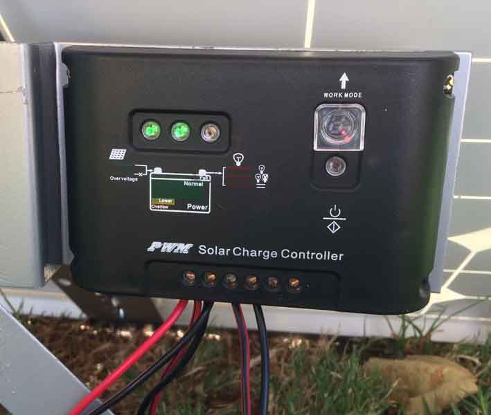
It has a first gen PWM Solar Controller on it, lacking much info about what the blinking lights mean. I'll figure that out shortly.
One nice feature is that the controller is mounted to the leg bracket, so it's visible and not in contact with the sun-heated panels when deployed.

solarpanelmount04.jpg


eta another design shortcoming for a portable kit, there's no strain relief on the wiring connections on the controller. All wiring movement or strains weigh directly on the set-screw style wire connections


Overall I'm not complaining about it, got it for a good low price, about 40% of the Renology kit and less than the 'cheap' Harbor Freight kits. And it's an inexpensive entree for me into solar power systems integration.


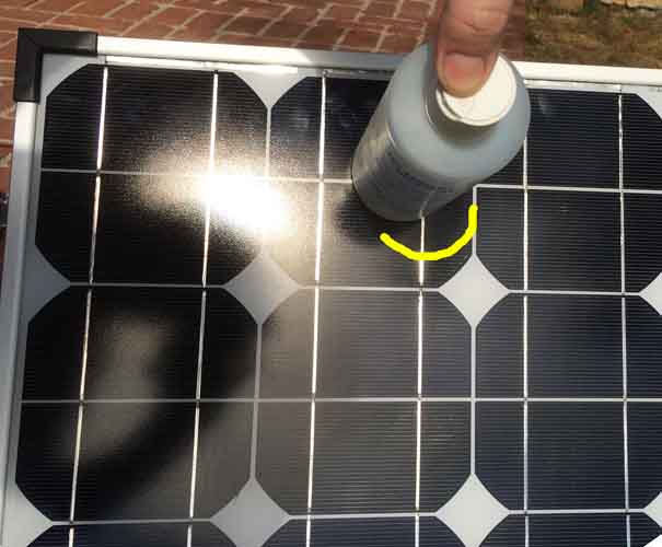
Lastly a quickie tip for aiming solar panels that I picked up somewhere online long ago. Using something like a can, cylinder, square box, anything with a flat bottom and perpendicular sides - place the object on the panel face and keep adjusting the panel until the object has no or very little shadow. Viola, your panel is aimed at the sun for maximal photon-gathering. Which is sort of moot, as the sun is moving 15 degrees every hour. So you'd have to fiddle every hour or at most ever two hours, to keep the panel axis close to on target. But it can make a big difference in panel output.

solarpanelmount03.jpg


And that's one other bit, on output. This panel setup has a rating sticker saying 5.7A. eh. in the general range for a single panel this size, maybe a little low. When I first set it up this morning I stuck a meter on it to measure and got a reading of only 1.6A. Hadn't had enough caffiene yet and was puzzled. Then I remembered 'state of charge'. I fully charged that pickup battery a couple weekends ago. I pulled the panel clips off it and checked volts, 12.68V, which is roughly 'full'. So the 1.6A was seemingly a proper trickle charge from the controller.
I suppose I could pound a couple lengths of rebar in the front lawn and measure the maximum Amp output of the kit that way.


eta

There is JUST enough room crossways on my roof rack for the panel to fit that way. 42-7/8" + luggage latches and 44" between roof rack rails. That would keep it manageable while I'm standing on the rear bumper. And the panel is 2' wide, so if the TV bracket retracts to within that, then it would really work nice. Couple that with turntable mount and yeehaw, could point the panel just about any direction.
 
Last edited:

Forum statistics

Threads
188,154
Messages
2,902,881
Members
229,582
Latest member
JSKepler
Top