rayra
Expedition Leader
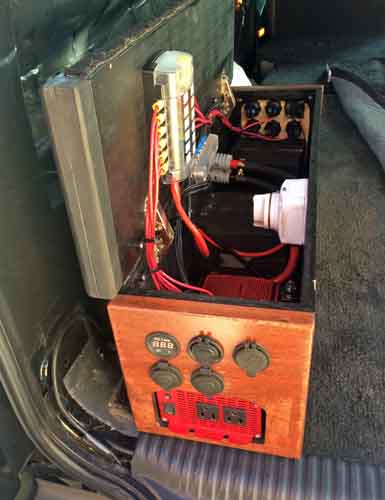
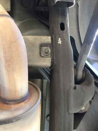
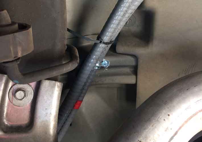
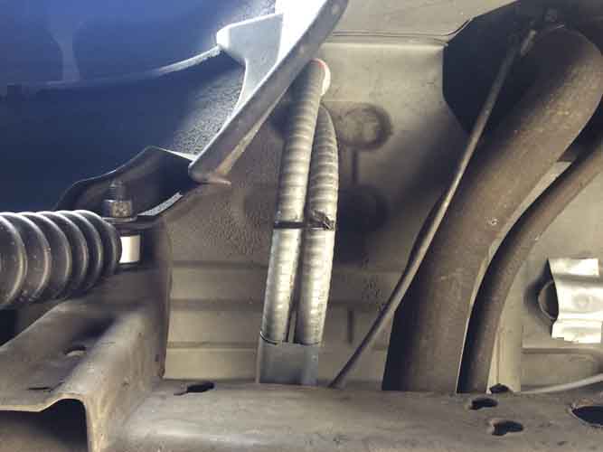
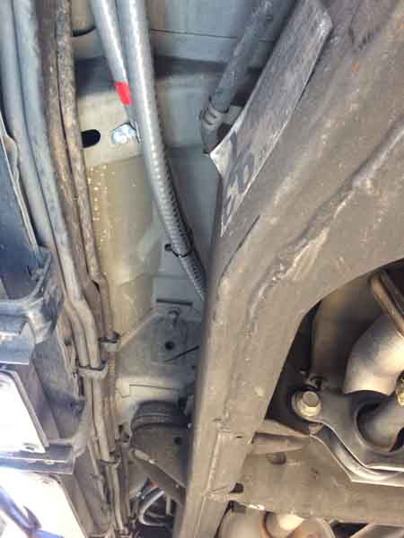
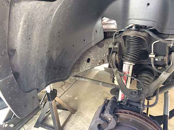
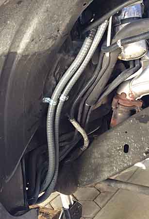
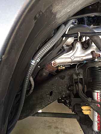
Made up the new solenoid->aux battery connection cable. Routed high and down to the terminal bolt, leaving ample clearance to work the rotary cutoff switch on the cable to the rear. And glopped some 'liquid electrical tape' on the exposed top connections on the solenoid.
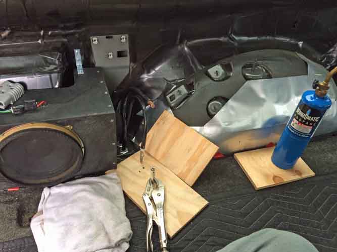
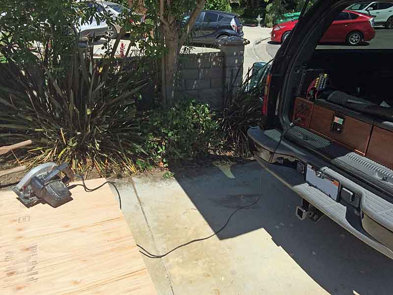
Then it was on to torch-soldering the other ends, inside the back of the vehicle (don' neeeed no stinkin' crimper). Ventilation, wet towel and extinguisher at the ready, all the tools ready for this silly exercise.

I used the vise grips to hold the anderson terminal connector with its cup up. I filled the cup with cut lengths of solder and did the initial heat / melt on my garage workbench. Then fed more solder into the melt until it filled teh cup about 2/3 the way up. Then carefully moved that molten mess into the vehicle. Got the torch back on the cup, grabbed the already prepared and positioned wire next to the cup and heated both at the same time, then seated the exposed wires fully. Go slow so you don't jet molten solder out. Do it right and the wire eases right in until the insulation makes contact with the lug.
No spills of molten solder, no torch burning of anything, and only a very light scorch where they tip of the anderson connector touched the plywood underlay.
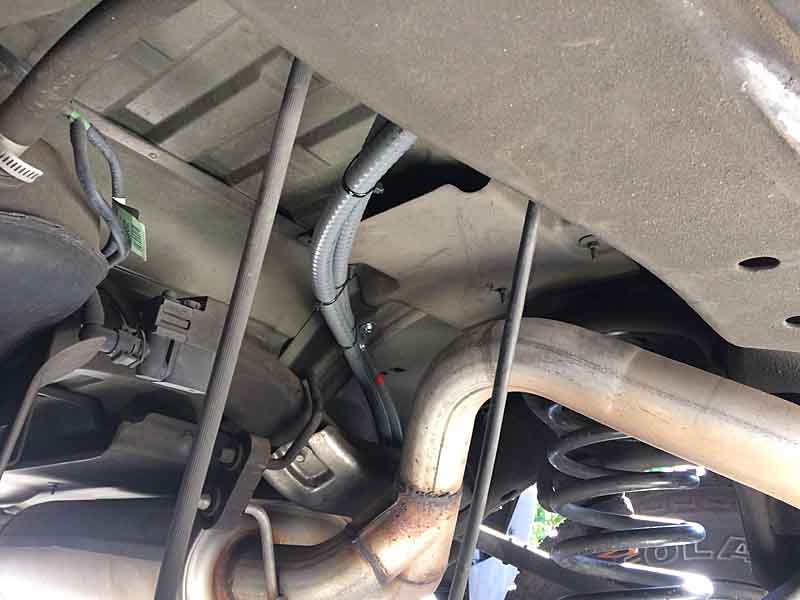
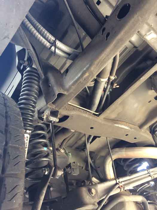
I did a bunch of manipulating of this stiff cable, to see how much I needed to comfortable align with the connector position. I wanted extra to have the reach for the soldering, but not so much I could stuff the djinni back in the bottle, so to speak. Make the hand bends, rough test fit, re-bend, test fit, unbend it all and shift the curve placements, test fit. Like some kind of circus muscleman strangling horseshoes.
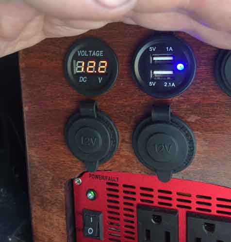
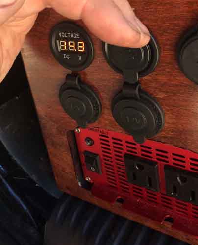
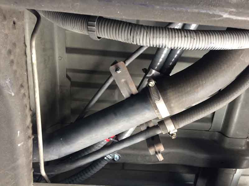
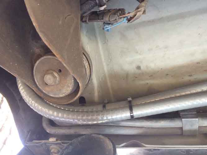
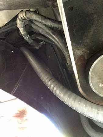
Finally got it sized well enough, committed with the bolt cutters, then did the soldering. All to arrive at this:
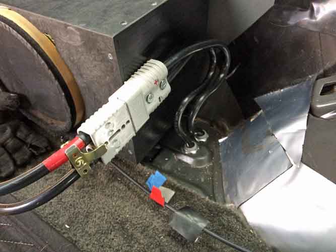
Now I go to try and find some welding cable by the foot, of some similar battery cable. 2 gauge will work for now, if I can't find 1/0. It's what WARN sells for their rear winch cabling kits, anyway. Get that Power Module coupling rigged and it's done.
10,692
Then it was on to torch-soldering the other ends, inside the back of the vehicle (don' neeeed no stinkin' crimper). Ventilation, wet towel and extinguisher at the ready, all the tools ready for this silly exercise.
I used the vise grips to hold the anderson terminal connector with its cup up. I filled the cup with cut lengths of solder and did the initial heat / melt on my garage workbench. Then fed more solder into the melt until it filled teh cup about 2/3 the way up. Then carefully moved that molten mess into the vehicle. Got the torch back on the cup, grabbed the already prepared and positioned wire next to the cup and heated both at the same time, then seated the exposed wires fully. Go slow so you don't jet molten solder out. Do it right and the wire eases right in until the insulation makes contact with the lug.
No spills of molten solder, no torch burning of anything, and only a very light scorch where they tip of the anderson connector touched the plywood underlay.
I did a bunch of manipulating of this stiff cable, to see how much I needed to comfortable align with the connector position. I wanted extra to have the reach for the soldering, but not so much I could stuff the djinni back in the bottle, so to speak. Make the hand bends, rough test fit, re-bend, test fit, unbend it all and shift the curve placements, test fit. Like some kind of circus muscleman strangling horseshoes.
Finally got it sized well enough, committed with the bolt cutters, then did the soldering. All to arrive at this:
Now I go to try and find some welding cable by the foot, of some similar battery cable. 2 gauge will work for now, if I can't find 1/0. It's what WARN sells for their rear winch cabling kits, anyway. Get that Power Module coupling rigged and it's done.
10,692
Last edited:

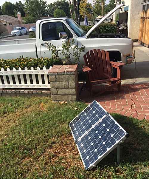
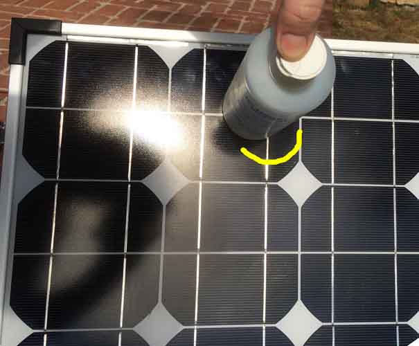
") ) while the panel is out in the direct sun.
) while the panel is out in the direct sun.