Herbie's Chevy Astrolander/ZMB Build Thread

Herbie

Rendezvous Conspirator
Top Transplant, Day 6

OK, I have been seriously slacking on the documentation end of things, but I HAVE been working. Here is an attempt to get caught up.

As always, there are more/bigger pics on my Picasa web album.

At this point in the build, it was time to attach the tent canvas to the van roof. The GTRV design basically sandwiches the canvas against the roof with this vinyl trim. When tight, this creates a (theoretically) waterproof(ish) seal against the van, sort of like a set of shingles.

IMAG0032.jpg


I used the salvaged vinyl strips to lay out the tent spacing and get everything lined up.

IMAG0033.jpg


In order to avoid more holes in the vinyl and canvas, I went ahead and used the strips as drill templates too - predrilled a dozen or so holes in a time.

IMAG0036.jpg


It was easiest to fill the strip with a line of screws, then stretch the canvas onto the screws using the existing holes, and finally drive everything tight against the van roof. This was especially important in the back corners because the tent is under extra tension from sewn-in elastic to keep things taught. I imagine when GTRV originally build these, they had a method for doing things without tension, and could just drill through the vinyl, canvas, and steel all in one go.

IMAG0037.jpg


And voila', several hundred holes and screws later, the tent is now attached to the roof of the van, making it theoretically weather-tight. At this point, the lifting struts are not installed, the pop-top was supported by a 2x4 from inside the van while I worked.
 

Herbie

Rendezvous Conspirator
Top Transplant - Lifting the Top

At this point in my documentation, I need to deviate from counting the "days" I've been working. Due to changes in work demands, a sick infant, and my wife's waning patience at being left for whole days or weekends at a time while I toil away at my buddy's shop, I'm just not getting whole days to work on the project. The upside is that since things have reached a certain level of completeness (see the last update), I was able to bring the van home again, and work on things for an hour or two here and there in the driveway. Progress comes in bursts, on afternoons when I can get away from work a little early and weekends when the baby naps or I can leave her with Mommy for (shorter) periods of time.

Instead, I'll try to capture "projects" as they are completed. Please remember that some of these projects span many days of short bursts and are often interposed with other projects, so things may appear out of order slightly.

Here then, I will cover the saga of "Lifting the Top". My goal, at the outset, was to be able to raise and lower the top on electric power, since I wanted my wife to be able to operate the top as easily as opening a sunroof. With the GTRV design, after releasing the latches, you must lift the top for 8-10 inches before the gas springs kick in and raise the top the rest of the way. When lowering the top, you have to hold it a bit above "fully closed" while you tuck the corners of the tent fabric away from the latches. For me this means putting my shoulder up against the top and standing up a bit. My wife is obviously smaller, and not quite as strong, so I was hoping to avoid this for her.

As always, more/bigger pictures on Picasa web album.

The problem with electric lifting actuators in this situation is packaging. The GTRV top is very low profile (lending the "Garagable" part to "Garagable Top RVs"), which doesn't leave much room for a bulky actuator. I was excited, then, to find these "tubular" actuators from Firgelli Automations.
Tube%20actuator1.JPG


The trick to this design is that the drive motor is contained within the actuator tube. This makes for a compact design, one that doesn't take up much more room than the gas spring that was included in the original design.

IMAG0069.jpg


First I tackled the upper brackets, where the actuator hits the pop-top. These brackets came from Firgelli, and I thought they were nice and compact until I started messing with them and found some oddness. First, the drilled holes weren't exactly square to the material, which made tapping them less than fun. Why tap? Well, I was concerned that if the mechanism ever failed while in the "down" position, it would be difficult (or impossible) to service the actuators since they'd be trapped under the cap, and a burned actuator would prevent me from raising the top manually. So instead, I tapped the brackets themselves then used button-head cap screws from the outside to bolt everything up. This way, if there was a problem I could simply unbolt the bracket from outside and raise the top manually. Its a good thing I did it this way.... read on.

IMAG0053.jpg


The Firgelli brackets weren't going to work on the van-side of things. They advertise "almost 180 degrees of rotation" from the bracket. I only needed about 40 degrees, but in an arc that wasn't compatible with the pinch-points on the brackets, so I had to make my own. I started by clipping a couple of corners from some 2" x 3/16" bar stock, then transferred over the critical measurements. The red is layout fluid, which when brushed on, makes it easy to transfer marks and measurements over to the steel. This is one of those things that (as an Electrical Engineer, not an ME or pro-machinist) I was glad to learn about when I was building Battlebots back in the last decade.

IMAG0059.jpg


After a bit more cutting, a little drilling and grinding, and some less-than-ideal welds, I have a couple of these brackets. These are the first project done by my "new" old welder. I've had this welder since the aforementioned Battlebot-days, got from another Bot-builder friend, but I'd never gotten off my butt and set it up until now. It's an old SIP design from Italy, with a few quirks which I will get around to fixing later, but for a hobbyist like myself, it should do ok.

IMAG0082.jpg


After paint, I made a couple of pads from cork/rubber gasket material. These should help seal against leaks and keep the roof damage to a minimum.

IMAG0084.jpg


The lower bracket and actuator in place, complete with stainless sheet metal screws.

IMAG0085.jpg


In the up position, everything was looking good. The actuators, even "unlocked" had enough holding power to keep the roof up without any struggle. "Locking" the actuators by shorting the motor terminals was built-in to my design and proved more than adequate to keeping things from moving. I started "small" by just moving the actuators a few inches, and everything was fine.

IMAG0086.jpg


After I tried to run the actuators all the way down, though, I found a significant problem. After a bunch of blown fuses and swear words, much probing, and disconnecting and reconnecting of wiring and bracketry, I was able to find the problem: The actuators aren't really built to take the load I was putting them under, despite the 150lb rating. The motor assembly is held in the actuator tube by a pair of plastic (!!!) standoffs that fit the extruded profile of the tube. Under heavy compression load, these standoffs were compressing and sliding, and the motor was hitting the cap on the actuator tube, pinching wires and shorting things as it happened. There may still be hope for this design, if I can get some metal motor mounts machined up, but for now the electric lift design was DOA.

IMAG0087.jpg


With a heavy heart, and 8 extra holes in the van roof :(, I gave up and fitted the original GTRV gas springs to the top. This isn't a "bad" design, it just wasn't what I was hoping for. Once again I have the problems of manually lifting/holding the top while raising/lowering, but so does every other GTRV owner...

On the upside, I was able to get to this point prior to the San Diego ExPo Meet-n-greet, so I was able to show off a mostly-functional pop top! :)

More to come...
 

Herbie

Rendezvous Conspirator
Top Transplant - Relocate Wiring and Overhead Console Project

Here is more of my retroactive documentation. In this installment, I tackled the relocation of the overhead dome/map lamp and add an overhead switch panel.

As always, more/bigger pictures on my picasa web album.

The main push for this part of the project was to deal with the aftermath of having removed the forwardmost structural rib from the Astro van roof. The GTRV steel reinforcing ring took care of the structural element, but there was also a couple of wiring harnesses that passed over this rib, one of them to feed the forward dome lamp and map lights that also hung here. The GTRV donor van had an aftermarket RV dome/map light in the overhead space between the reinforcing ring and the windshield/rearview mirror area. I liked this placement, but I was pretty sure I could make mine look more factory by reusing the original GM light assembly.

IMAG0063.jpg


Like the GTRV solution, my implementation began with a piece of aluminum sheet. I didn't like the way theirs was sort of bodged on, though, so I started by bending a mild angle to fit the top of the windshield header. This gave me a batter flat-to-flat surface to drive a couple of sheet metal screws though. The bend was mild, so I wasn't worried about cracking, but if there had been much more to it, I would have felt compelled to anneal the sheet before bending. Behold my super-quick-and-dirty metal brake, basically a few pieces of angle stock in a vice. The top pieces clamped on with c-clamps keep the bend straight and prevent me from over-bending and risking cracking.

IMAG0066.jpg


Next I started laying out placement of the dome lamp housing, as well as a plate to mount some switches. Is that carbon fiber? Yes, it is. Why carbon fiber? Because when you're an ex-Battlebot builder you've got big sheets and even bigger piles of scrap CF plate lying around in your shed, looking to get used. Plus, its nice for mounting switches because its a bit thicker (and more rigid) than a thin metal sheet but is still easy to machine with a dremel and a file. The extra material thickness seems to hold the switches more tightly.
IMAG0068.jpg


Zardoz is displeased. Actually, these are clearance holes for the wiring coming off the backs of the switches. The carbon plate is spaced off of the aluminum mounting bracket to allow for the thickness of the headliner (once reinstalled), but the wiring needs to go back up under the headliner to the rest of the chassis loom.

IMAG0070.jpg


Here you can see the how the bracket fits onto the reinforcing ring and windshield header. I'm extending the wiring harness that used to follow the roof rib. I pulled matching-color wiring from the donor van to extend all the wiring, so there would be no troubleshooting hassles down the line. All the new harnesses were sealed with weather-tight heat-shrink crimps and then wrapped in that sticky cloth wiring loom tape. I even wrapped-in the factory clips so the wiring loom is secured to various bits of the roof structure as it routes along the van. All of this will tuck up under the headliner when reinstalled.

IMAG0075.jpg

Here is the switch plate, ready to install. At this point in the process, I was still planning to use the electric actuators to lift the top (see previous post), so there are two momentary rocker switches for the actuators, plus a DPDT switch to lock the armatures, plus one spare. The divorced actuator switches were so that I could fine-tune the tent tension in case the motors didn't lift at the same speed. I ended up chucking this design, though, so I now have a really cool carbon fiber switch mount with four unused switches.

IMAG0079.jpg

And the dome lamp and switch plate installed to the mounting bracket. The dangling blue connectors were the leads to the actuator motors so that I could use the switches to move the actuators prior to final installation. I do wish I had just mocked-up the (complicated) switch wiring onto a temporary board before I found that the actuators would have to be scrapped. It might have saved me some effort here...

IMAG0081.jpg

And one final little project. I made a bend-template to make a bracket to hang my ScanGauge from the windshield header above the rear-view mirror. I ran the cable up the A-pillar and now the gauge hangs in a comfortable field of view above and to the left of the mirror. The bracket is from a chunk of scrap titanium, bent on the same bending rig shown above. Yes, I have scrap titanium too. This chunk was originally salvaged from a British Heavyweight that fought (and lost) in Las Vegas (Battlebots Season 2), and had since been used in a variety of my beetleweights and flyweights in bouts all over the Southwest.
 

Herbie

Rendezvous Conspirator
Side Project: Swivel Passenger Seat

OK, with this update, I should be more or less "caught up" with documentation vs. the state of reality on the project, at least with respect to things with a significant time investment.

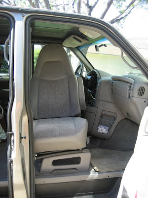
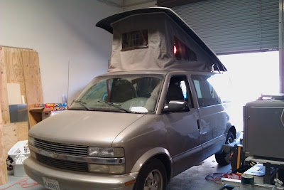
I finally got around to finalizing a GOOD fix for my issues with the swiveling seat. A rearward-facing seat (at least in the front passenger position) has been a core part of my interior design from almost the beginning. As soon as basic measurements and layout attempts proved to me that I would need to use some variant on a VW Weekender/Westy layout, I wanted to have the expanded living space of the front row facing aft.

As usual, more complete and larger images available on my picasa web album. I will also make reference to some other photos from the first draft installation.

My first attempt at this was to buy an off-the-shelf "bolt-in" swivel mechanism from 
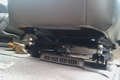
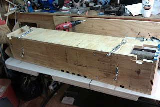
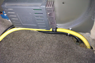
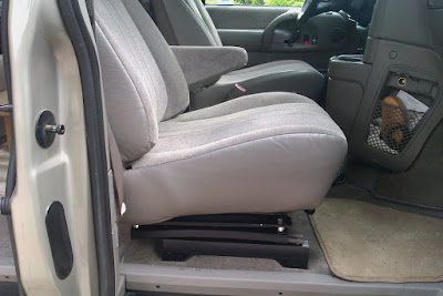
Discount Van-Truck (hereafter "DVT"). The idea is that this swivel plate bolts in between the stock seat and slider rails. Unfortunately for the Astro/Safari version, although the bolt-spacing is correct, it doesn't really take into account that the seat rails and seat bottom are curved. In order to accommodate this arch, I had to add some spacers to the bolts:
IMG_4876.JPG

Combined with the swivel plate itself, this adds up to over three extra inches of seating height. This made it tight, even for shorter passengers. With the headliner removed to do all of my other work, I was pretty uncomfortable letting anyone too tall ride in that seat, lest they risk a head injury on exposed metal.

IMG_4870.JPG

The other problem with this design is that the stock seat has some rearward rake built into the rails. This lifts the front of the seat and makes seating more comfortable, especially with the limited legroom. As you can see in the above picture, though, this incline is static and below the plane of rotation of the seat, so as you swivel the seat you go from a sideways slant to the front edge of the seat being much LOWER than the rear when fully swiveled. This was VERY uncomfortable.

Both of these "features" alone warranted a new plan of attack.

IMAG0090.jpg

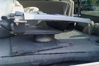
When I scored my donor van, I was pretty excited because it included TWO swivel seat bases. I also liked that these had a very beefy locking prawl so they felt securely locked when facing forward. Unfortunately they shared the same design flaw with the rear-rake built-in below the plane of rotation.

IMAG0089.jpg

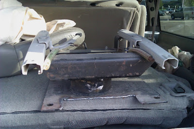
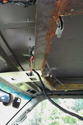
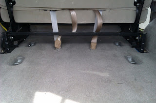
That wasn't the worst of it, though. It seems that GM had made some small but significant changes in the interior portions of the Astro/Safari van somewhere along the way. Despite having an identical outer unibody, the 1995 donor van had a few key differences to my 2003 van. Under the rear of my front seats there's a small duct outlet that blows HVAC air onto the feet of the passengers in the middle row. At first I thought I could utilize the GTRV donor swivel base by just notching the back of the plate to clear this outlet. I quickly went after it with a plasma cutter before I really understood what was going on. It turns out, that the vent outlet has ducting behind it (duh!), in the form of a very wide and flat plenum that sits under a good portion of the seat. This is why the passenger seat is up on those riser rails you can see in the first picture. Where the feet touch it is flat, but most everywhere else sits 1-2" higher with ducting, carpet, underlayment, etc. These flat-bottom seat bases just weren't going to work.

I looked at a variety of ways of just trying to put little "feet" on these bases to use them, but it always stacked up to making the passenger seat too high again. With all of the clearance needed for the various levers, there just wasn't an easy way to chop two or three inches out of the design without basically rebuilding it from scratch. Rather than head off down that road, I decided to leave the swivels intact for resale, and went after making the original DVT swivel base work "right".

IMAG0100.jpg

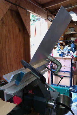
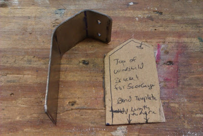
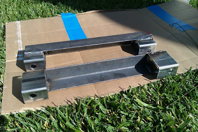
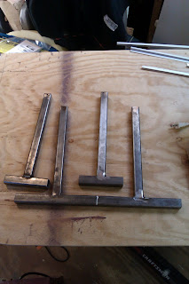
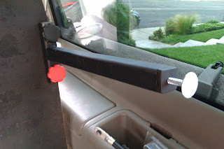
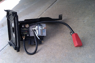
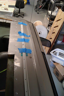
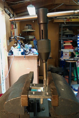
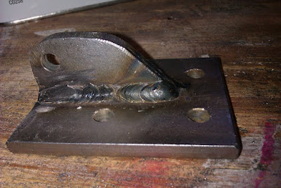
After a lot of back and forth, I built these. They're pretty simple, just a couple of short sections of 1.5" x 2.5" tubing, with some angle stock welded on. The second project from my new-old welder. The more I work with it, the more I realize it will need a minor overhaul to fix the design issues with it. Fortunately others have gone ahead and documented how to do that.

IMAG0107.jpg

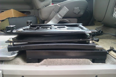
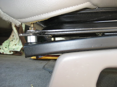
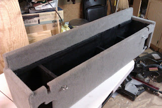
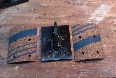
Here you can see everything stacked up. Unfortunately I still have the "curved" slider track under the swivel plate, but this was sort of necessary because if the slider was on top of the swivel, you'd have too much of the locking lever sticking out between your legs when the seat was fully rearward. This keeps the lever handles in a better position. More importantly, you can see that the plane of rotation is now mostly flat (depending a little on the slider position), and that the rake is built-in above the swivel plate. In this photo the swivel is "facing" rearward, and the 1" tubing spacers on the left raise up the front of the seat in all positions.

IMAG0111.jpg

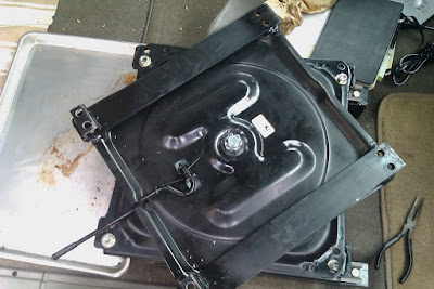
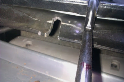
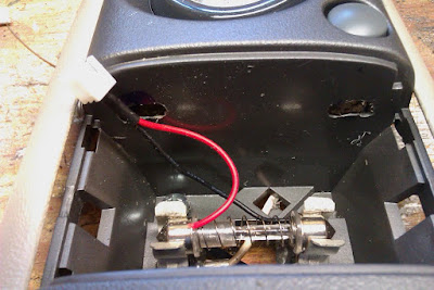
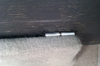
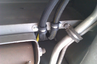
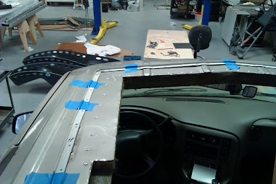
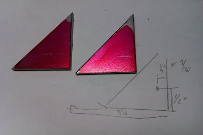
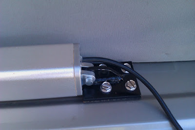
Here's the swivel plate "mid swivel", and the detail of the locking lever. One problem with both original swivel designs is that they only locked in the forward position. When facing rearward, reaching to grab something off the dash or trying to adjust your position with your legs would make the seat turn instead of moving your body, like pushing one of those shopping carts where all four wheels swivel, or a boat with no keel. Sort of annoying.

IMAG0104.jpg

Fixing this was the easiest part of the whole project, I just nibbled out another notch with a cutting wheel on my grinder, so now the seat locks in the rearward position as well.

IMAG0117.jpg

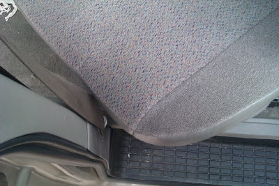
It is hard to see here unless you know what you're looking at, but the other minor improvement was to heat and bend the locking lever slightly, so that the handle comes "up" a bit and fits the contour of the lower seat a bit better. It gets it out of the way so you're not banging your heel on it if you cross your legs under while seated.

IMAG0113.jpg

All told, the passenger seat now sits almost 3/4" lower than stock, instead of the 3+ inches higher than stock. The extra headroom just makes me feel that much safer for passengers since the GTRV reinforcing ring does seem to sit a tad lower than the original roofline, but I didn't want to drop things too much lest the armrest in the door be wildly out of whack against the arm rest on the seat. Building my brackets this way also moved the seat rearward about and 1.5 inches. This makes up for the awful passenger foot room more than you'd think, since the foot well is tapered. Any further and I was worried the upper seatbelt pickup would be too far forward.

IMAG0114.jpg

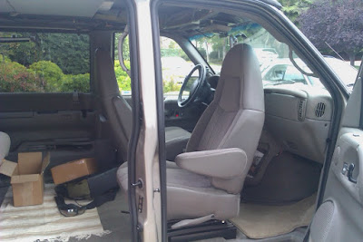
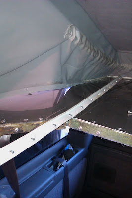
As currently mounted, the edge of the seat just clears the B-pillar if I swivel the seat clockwise. If I want to go counter-clockwise, I have to move the seat back to the fully upright position first. I still could move the seat inboard another inch-and-a-bit if I use the other mounting holes, but so far this seems fine.

IMAG0115.jpg

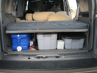
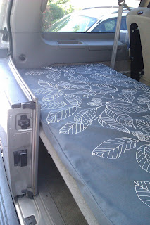
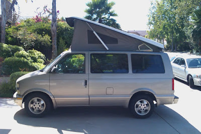
And now I can finally enjoy a proper "living area" facing the bench seat opposite with enough space for a table for eating or cards.

Two answer two popular questions:
1) No, I wouldn't use the seat in this position while traveling. The seatbelt anchors aren't really in the right place, and it would make my wife carsick faster than an alpine road anyway.

2) Not sure if I plan to do the same to the driver's seat or not. Because of my planned layout, my Edgestar fridge will most likely be behind the driver's seat when camping, so I wouldn't be able to swivel without a lot of shuffling around. I could test to be sure, but I also think the driver's seat would have to be inclined to an uncomfortable angle to clear the steering wheel anyhow. That said, having "facing" seating for four adults would be cool if we got stuck in a rain or something...
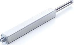
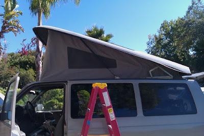
 
Last edited:

RocKrawler

Supporting Sponsor
Wow, you've been the busy little beaver! I want to eventually make my fronts swivel if I can find another satisfactory location for the ARB fridge (it fits perfectly as a center console for the front buckets now, no slide or bracket needed!) It will likely find its way to the back of the van if my new rear galley design works out as planned. You and the other member of the "Amazing Astro Duo" seem to have a lot of cool tricks that I will likely mimic on a larger scale with Van Diesel. I just picked up a nice little 110 Lincoln Mig for my projects not done at the shop to make things easier.
 

zuren

Adventurer

Is that the OEM dome/map light for your van? The dome light in my Express is as basic as it gets that I have to turn on/off with the dash dimmer switch and would like to retro-fit something a bit nicer.

Thanks!
 
Last edited:

Herbie

Rendezvous Conspirator
Dome Lamps, Mini-Update: LED Dome Lamps

Is that the OEM dome/map light for your van? The dome light in my Express is as basic as it gets that I have to turn on/off with the dash dimmer switch and would like something a bit nicer.

Thanks!

Yes, that's the OEM for an Astro/Safari, a least for a 2003 model year. My 1995 donor is a weird transition-year so still with the old-style interior, so I'm not sure when GM made the move to that style. Each van gets two, by the way, one just behind the front row, one just behind the second row, apparently identical.

It's a 3-wire connection to hook up: +12v, GND, and Switched-Ground that is closed when the door is open or some other trigger turns on the dome portion of the light (dash dimmer, keyless entry, etc.). If your Express uses a similar switched-ground system (which I would expect), you could probably upgrade to this just by adding a permanent ground (for the map lights) with a terminal ring through the mounting screws.

This leads me quite well into another Mini-Update:

When I was ordering some other parts from JC Whitney, I needed a few more items to get to the free shipping threshold, so I went ahead and ordered a pair of these Ultraflex LED Dome Lamps, in the 2.5"x1.5" size.

These are a 24-LED array, but they needed a flat place to mount, so I had to do a little work.

IMAG0152.jpg


The kit includes a variable-size shunt that fits in place of the original incandescent bulb and provides a 12v/gnd connection. Then I notched the enclosure with a couple of slots.

IMAG0151.jpg

Then I cut this shelf from a piece of scrap ABS plastic. Excuse the crude work, I was going fast trying to finish before returning to my Daddy duties on a Saturday. The ABS was from an unused portion of a drawer organizer in the recycling bin.

IMAG0154.jpg

The tabs on the ABS mate to the slots in the housing. Two on one side, one on the other. The ABS is about an 1/8" thick, but is fairly flexible, so easy enough to bend to insert and remove from the slots, which is important since the mounting holes for the dome lamp assembly are behind it, on either side of the original bulb.

IMAG0155.jpg

The LED matrix then is affixed to the ABS with the supplied double-stick tape (already applied to the back of the PCB). The mating connection is plugged in to the shunt adapter.

IMAG0156.jpg

In this location it has 1/4" or so of relief from the diffuser lens. Unless you're really looking, you can't tell there's anything different under there.

IMAG0160.jpg

Until you turn it on. Compare the brightness against the incandescent map lights. These will get converted to LEDs too, as soon as I find an LED kit with an appropriate bulb adapter or have time to make a few from hacked bulbs.

IMAG0158.jpg


This is a daylight shot, and you can already see the brightness of the LEDs (foreground) versus the incandescent bulb (background). These have made a huge difference in the ease of buckling baby into the car seat after dark. They are NOT a perfect white, they do cast a bit of a blue hue, but for this purpose and the price, I am quite happy. When I do the map lights, I may be a bit more careful about the color temperature as map reading, etc. is hard under bad lighting. I'm also considering red LEDs for the front map lights at least, as an option to help preserve night vision.

(Large pics as always on my web album).
 

Herbie

Rendezvous Conspirator
Battery Box and Bed Platform

Once again I'm having to play catch-up to get the blog updated with the state of construction on the Astrolander project. These projects still span multiple days/evenings, so updates are mostly "project" based. Here then, is the coverage for the project to build a platform to extend the fold-back bench/bed to a full 72" and also a box to hold the house battery. As always, more images with annotation available on the web album.

IMAG0332.jpg

The project starts with the battery box. Pretty basic stuff, 3/4" CDX plywood screwed and glued. I chose CDX for the outdoor-rated glue since I knew the box would be carpeted anyway, plus it was $18/sheet instead of $45/sheet for the nice birch stuff!

IMAG0357.jpg

The design of the box looks a little odd at first, but the rear edge of the box actually supports the forward edge of the bed platform, hence the extra height. Everything is designed to maximize space, so the forward part of the box nestles right up to the back of the bench/bed and part of it will be UNDER the seat-back as it folds back. The cutouts on the front (left) side of the box are to clear the movement of part of the bed mechanism. The upper notches are to clear the "arms" of the bed as it folds down. The inner "walls" of the box provide strength for the tie-down system (more on this below) and form the inner battery tray that helps keep things from moving around. In this photo I'm trial-fitting the Group 31 AGM battery, only to find that it's just a hair tall with the top posts, so I ended up switching to a Group 34 battery.

IMAG0362.jpg

As I said, the inner walls of the box actually provide the strength for the tie-down system. In this shot the box is on its back. The fasteners for the hooks and eyes go all they way into the vertical dividers, making everything plenty strong.

IMAG0402.jpg

Here's the back of the van where the box snugs up against the bench seat. My conversion van bench/bed is mounted to the floor in between where the 2nd and 3rd rows would have been. I utilized the existing attachment pins in the floor for the original 3rd row bench to mount the box. The hooks you can see in the above photo grab onto the aft pins in the floor, and then shackles and turn buckles tie into the forward pins to pull the box forward and down, making everything rock solid.

IMAG0399.jpg

The inside of the box was then coated in brush-on bedliner, then everything was carpeted with a pretty decent match for the OEM floor/lower trim carpeting.

IMAG0423.jpg

Next was to weld up the support legs for the back portion of the bed platform. These legs ended up spaced about 16-1/2" on center, but the platform is 29" or so deep, so I made the tops of the legs into "Tees" so that there wouldn't be a long unsupported span in the fore/aft direction.

IMAG0433.jpg

The bottom of the legs were tapped for threaded riser bolts so I could adjust the final height to level everything out. The legs attach to the platform with knob-headed screws into teenuts in the platform. I wanted a completely tool-less way to remove the platform and break it down completely flat for easy storage in my garage when not in use.

IMAG0430.jpg

The platform attaches to the battery box with a couple of removable-pin hinges. Again, a tool-less way to attach the platform to the box, but it serves a more important purpose also:
IMAG0446.jpg

The whole platform hinges up to allow easy access to the stuff underneath. In particular, I wanted to make sure I didn't block access to the jack compartment on the passenger side (right corner of photo). As it stands, the rightmost leg sits directly in front of that access panel. Eventually, I'll probably add a cam-lock strap or chain at the rear edge of the platform to engage with the stock D-rings at the rear of the cargo area, which will hold the platform down and keep the cargo underneath from moving in case of accident.

IMG_5154.JPG

When the platform is down, there's just enough space between the legs for three tall Rubbermaid containers, or two tall containers and one short one with my Coleman stove on top, or two containers and a 7-gallon water jug. Not as fancy as some of the great drawer systems I've seen on the epic storage system thread, but this system is flexible, and more importantly, it lets me easily move the packed bins back and forth from the garage, which makes packing for trips and unpacking afterwards super easy.

IMAG0448.jpg

With the addition of some firm 2" foam, the bed platform mates up perfectly with the bench seat as it lowers into a bed, making the sleeping area roughly 56" by 72". I bought the slip cover material at Ikea, and it was sewn by my Mother. I would have done it myself (hey, a sewing machine is a power tool too!), but I was running out of time prior to Overland Expo 2011, and Mom was eager to help. Admittedly, she did a much better job than I would have. Thanks Mom!

The only bad news here is how snug the platform is to the rear doors. I plan to build some drop tables onto these, so I'll have to modify the platform at a later date to provide a little clearance. Oops!


IMAG0436.jpg

Getting the battery box built meant I could also install the house battery and split-charging system. For the split-charge controller, I gambled on the T-Max system from Summit Racing. Definitely not as full-featured as the offerings from IBS or National Luna, but way way cheaper, and budget was a consideration here. If or when it fails, I'll consider upgrading, but for now it's working great. I mounted the display/control interface on the lower dash next to the doghouse on a custom bracket. I do actually like the display - during normal running it only lights the charging LEDs at the top left, you can hit "display" to see the state-of-charge on the main (starting) and aux batteries at any time. I like that it's completely dark when the engine is off, since the LEDs could be annoying at night.

IMAG0374.jpg

The other half of the T-Max system is the massive solenoid. I used some scrap aluminum to make a mounting plate that I riveted to the bottom of the mounting bracket that holds the starting battery and ECU mounting frame in the engine bay. The block on the left is one of two 150A breakers (one at each end of the run of cable back to the box in the rear). I used extended side posts to tie the extra power and ground cables directly onto the main battery.

IMAG0378.jpg

The main run of cables from the engine bay to the battery box was made by cutting up a new set of 2-gauge jumper cables. I like using jumper cables because they're fairly flexible and inexpensive compared to buying other big cables by the foot. In this case I opted to separate the positive and negative and cover each with a tough outer braid. For the entire run these are fixed to the van BODY, and always above the sub-frame because I know the body-to-subframe distances will be changing soon when I install the lift kit (which includes body-lift pucks.)

IMAG0386.jpg

The cables enter the interior just aft of the fuel filler and stay behind the plastic interior trim (removed in this photo) until they enter the battery box where they connect to the second breaker, fuse panel, and house battery. For now I'm just running my Edgestar fridge and house lights (rewired the vans dome and map lights to take power from the house battery), but eventually the HAM radio and a few other goodies will also take power here.
 

rotor

Observer
Wow, I really like your battery box bed platform solution! If you don't mind I think I might copy that idea. Looks great and you are doing an amazing job on your astro.
 

Forum statistics

Threads
185,911
Messages
2,879,535
Members
225,497
Latest member
WonaWarrior

Members online

Top