We need a Unisolar hack

Wanbli

New member
This can be done, I have discected a PVL-68 to create a foldable solar panel to use while in the back country. Reassembling it as a 2 X 2 array of 3, 3, 3, and 2 panels.

Doing so is not especially technically difficult, but is a bit involved mechanically. The biggest challenge is dealing with the three electrical busses that run down each side of the array, and the bypass diodes.

The PVL-68 is arrayed as 11 panels wired in series. More accurately, each panel is actually 2 cells. Each of the cells is wired independently on either side of the panel. The two series strings of cells are wired in parallel at the connector end of the array. Each cell has a bypass diode for a total of 22 cells and 22 diodes in the array.

I cut a PVL-68 into for segments of 3, 3, 3 and 2 panels. The 2 panel segment included the junction box and external connector cables.

Looking closely at a PVL array, it is easy to see the physical edges separating each panel, so slicing between the panels at the junction line is straight-forward - until you get to the edges, where the bypass diode and conductive busses transect the panel separator line.

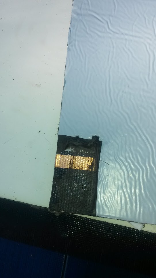
The PVL series arrays are very well made. From the back is the cold-bonding mastic which allows these panels to 'peel and stick' to metal (and other) surfaces. The mastic is sticky (surprise!) but easy to scrape away. Above the mastic layer is a very tough plastic membrane which is the bottom mechanical substrate and covers the bus strips, diodes, and photo diode grids. The plastic membrane is harder to remove - it's tough, and well bonded to the layer above - but can be cut away with a razor knife and patience. You will need to cut away this membrane in the areas where the busses need to be exposed for disconnection of the bypass diodes, and eventual rewiring.

You must decide on an approach to disconnecting the diodes, and severing the conductive busses. Looking closely at the array from the top, you will notice 'bumps' in the top membrane on either side of the array right at the dividing line between adjacent panels. These 'bumps' are the bypass diodes. For the purposes of cutting the array into sections, the diodes are very inconveniently located.

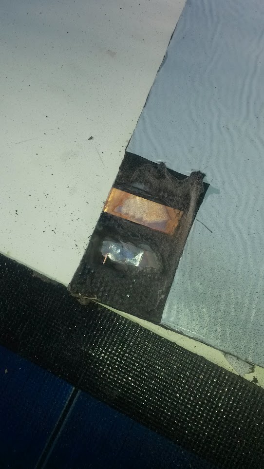
If you choose to preserve the diodes for use in rewiring the array segments, then you will need to dig into the back of the panel, 'excavating' through the membrane around the perimiter of the diode to expose it's axial leads, and the solder pads where the diode connects to the busses. Once you have the diode exposed, you can carefully cut one end at its solder pad and gently pry the lead up from its embed. After completing this (one for each side of the line where the panels are to be severed) you can cut through the conductive busses to separate the array into segments. Be careful cutting through the busses so that you sever them exactly centered on the line between the panels. This will make it easier to prepare the busses for rewiring.

In my case, I chose not to reuse the bypass diodes at the panel sever points, but to replace them with new bypass devices when rewiring the array, so simply cut through them as well - eliminating the 'excavation' step for now.

Once the array is cut into the number of panels desired, the reassembly process can commence. That's for another post.

I'm hoping beyond hope that you're still monitoring this forum....
I need more specifics on how to get the panel to work once it's cut. I cut one section off to shorten it and I cannot get anything out of the panel at all. Please respond if you see this. I notice your website is for sale, so I hope you're still monitoring...
 
Last edited:

dwh

Tail-End Charlie
George, I'm hoping beyond hope that you're still monitoring this forum....
I need more specifics on how to get the panel to work once it's cut. I cut one setion off to shorten it and I cannot get anything out of the panel at all. Please respond if you see this. I notice your website is for sale, so I hope you're still monitoring...

Send him a personal message. That'll toss off an email to him.
 

SkiFreak

Crazy Person
Send him a personal message. That'll toss off an email to him.
About a year back I tried to contact this guy a few times, but never got any response, so I don't like your chances.

That said, I can probably answer your questions...
There are two copper rails down each side of the panel. If you cut the panel then you lose the electrical connection between those rails.
In order to get the panel to work, all you need to do is connect all of those rails together where you have cut the panel.

The images are of my own PVL panel, which I shortened as a "proof of concept". I do not own any ePVL panels (the generation of panels after this one), but I expect that they would be very similar.
If you have any questions, send me a PM. Unlike raysun, I will reply. :)

UniSolar_01.JPG UniSolar_02.JPG
 

o5willys

New member
With he help of this thread I decided to give it a go and cut a pair of panels for myself.

9Ilv9K9fHokDaUsLxR6nL42sglAktjakaGSFPS9yxAY=w542-h963-no

8XwHWZMsb2_TOdHPbjPTt2TdluemY-OLJqoJORE-L8Q=w542-h963-no

FxmbFef3IEAVab0oZDsFcT2GAEdLQ2tZ0-r2xE-dGXc=w542-h963-no

zMdXePm8xS0NzPyy-P9HDaFtuLhgK6yc77QrCZRIWmE=w542-h963-no

TVmuVRj6oSSeViEktmIrZ2wO4jR_GbsujH3qFWdCViM=w542-h963-no

sv8UPe_DMmpn98ApxGiD168vqg6SHDuiQv5TcT4-Nd0=w542-h963-no


These are the PVL version not ePVL.

The process is pretty straight forward. I cut between the cells with a ruler and razor blade and then cut the ends with some heavy duty scissors. Then I cut the white backing and "rolled" the mastic back. I just pushed hard on the mastic and balled it up to get it out of the way. I then used a wire wheel on the dremel to expose the metal connections.

This is where I failed a bit. I exposed the diode on the first panel I worked on (you can see the wire in the image above) but I do not know what diode to replace it with so I just wired the panels back together without a diode. If anyone knows to to fix this I would love to hear it.

The last step is to solder 4 wires to the 4 spots I had exposed and simply connect the dots. I also epoxied the back on the exposed area to help secure the wires and seal up the exposed electrical connections.
 

SkiFreak

Crazy Person
This is where I failed a bit. I exposed the diode on the first panel I worked on...

I have found that it is easier to cut the panel about an inch or so lower than the gap between the cells, that way you avoid the problem of going anywhere near the diodes (on a PVL panel).
This approach works fine if your goal is simply to shorten the panels and you are happy to "waste" one of the cells.

Happy to see that this thread has been useful to someone. :)
 

ikk

Adventurer
I have a 68 watt PVL panel that I use for camping. I have removed all the tar backing and currently roll it up for storage. I would like to cut this panel up into sections and be able to fold it up as it would take up a lot less space. as the Panels are already waterproof I was thinking of using some type of thick adhesive tape to connect the panels together and leaving some space for the fold. Has anyone tried this?
 
Last edited:

vinay stanley

New member
Any Update on this Unisolar Panel Hack

Hi any update on the Unisolar Panel Hack and how to avoid cutting the diode and also saving and using the remaining panel.
Any detailed photo would help, as these panels are hard to get by today.Grateful for any help coming in in the forum or if sent
to vinayst@gmail.com
 

SkiFreak

Crazy Person
As I have mentioned previously, it is simpler to cut the PVL panel below the diode, but this means that you sacrifice one of the cells. I do not have ePVL panels, so I do not know if it would be the same with them, but I expect that it is.
Trying to dissect the laminate is definitely challenging, hence my above suggestion. The cells also have buss bars on the top and bottom and on each side. Actually each cell is really two cells electrically, not one.
So, shortening the panels is not that complicated, but turning them back into individual cells is, in my opinion, way too much work.
For detailed photos... check out my previous posts in this thread.
 

Anthony 78

New member
Hey I don't know if your still around but it would be great if you had some video on how to do this
If you can walk me through it that would be great
I have 2 136w PVL solar panels I would like to make them shorter
 

SkiFreak

Crazy Person
If you can walk me through it that would be great

Maybe when I get around to doing the actual modification of my panels (opposed to the proof of concept I did) I might do a video, but that will be some time off, so don't hold your breath.
To be honest, the electrical concept is not that difficult. If you cannot gain enough confidence to do this modification from looking at the images I posted, then maybe this is a project you should not attempt.

Before doing the modification on my own panels I will be looking for a simpler/better way to remove the mastic on the back of the panels, because I remember that this was a bit of a pain.
You have to remove the mastic before you can grind the back of the panel to expose the buss rails. I would then use some Sikaflex 11FC (or similar) to cover the buss bar connections, The same type of Sikaflex could also be used as a replacement for the removed mastic.
I should add, it would probably take some skill to do it this modification neatly.
 

Kalisaya Power

Supporting Sponsor
Check out the KaliPAK. Its a lithium Ion battery that has 558Wh and comes with an included 40-Watt Solar Panel. Just 14lb, its all the power you need for all your personal and 12V devices. FYI I can get you 10% off...

Kalisayapower.com
 

john61ct

Adventurer
Check out the KaliPAK. Its a lithium Ion battery that has 558Wh and comes with an included 40-Watt Solar Panel. Just 14lb, its all the power you need for all your personal and 12V devices. FYI I can get you 10% off...

Kalisayapower.com
Link to replacement batteries please
 

Discovery76

New member
This is great information. I am so happy to find this. I have several 138 panels that I want to cut in half and make into 6, 68 watt panels. I found this youtube video, which I wanted to share.


It shows how to cut the panels to save the diode.

One thing that I am unclear on is for the panel with the diode that you save you connect the diode from one side to the diode from the other side with a single wire and then solder, seal, and use the factory installed connectors at the opposite end of the panel to connect to your batteries.

Then for the second panel that does not have the factory installed connectors do you solder a wire to the bus bar on each end and one is positive and one is negative?

I wouldn't mind loosing one section as SkiFreak discribed. In that instance do you just connect all 4 bus bars together for half of the panel that has the factory installed connection box and then of the half panel that does not have the factory connection box you solder a positive wire to the two bus bars on one side and a negative wire to the two bus bars on the other side?

I am sorry I am very new to solar and I am still learning how all this works, but these panels cut in half are going to work really well for us.

Thanks!
Dave
 

Forum statistics

Threads
185,840
Messages
2,878,741
Members
225,393
Latest member
jgrillz94
Top