Anyone running a Renology Wanderer PWM with a Flooded battery?

rayra

Expedition Leader
... and can / would relate the top voltage you are getting with it on such a battery?

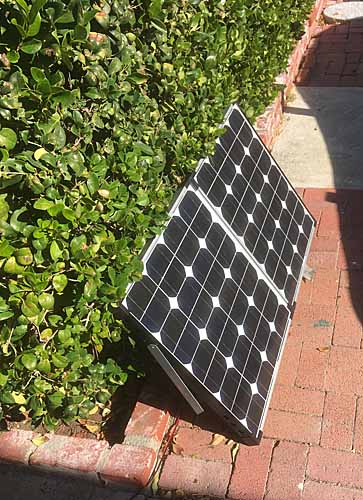
I have a folding panel kit from a defunct company, a no-name PWM controller, with the panel on my roof. I get a good peak voltage of 14.4 on the bus during the day and just a couple hard-wired dual port USB inverters on the Aux circuit. There is some parasitic loss there, but not a lot. Checking in the late evening I'm getting just a bit over 12.6V on my Aux group78 normal flooded battery. As a side note I rarely get my Starter battery over 12.25V. I don't drive it enough (3-4x/wk, local errands, mostly) and the vehicle computers and other electronics and another pair of USB inverters aren't helping that situation.

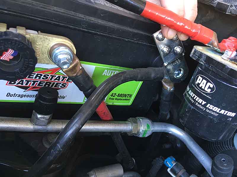
I had hoped for higher resting voltage on that Aux, with the solar setup semi-permanently attached and running. Too, I'd hoped for some greater power transfer / 'leveling' between the two batteries when I'm driving it around. Even with my simple 200A solenoid connection between them and a long regional road trip, I'm still getting a .2-.3V disparity between the batteries. Which are both Interstate Group78, purchased about 4mos apart IIRC.
ETA - measured at the battery terminals, vehicle shut down and panel disconnected.
ETA - Aux is 25mos old, Starter is 12mos old. And I’ll soon be buying a fresh one and installing it as Starter, bumping Starter to Aux, and Aux is going to my old pickup
And I’ve just confirmed electrolyte levels are good in all cells

I've already re-working the USB inverters to be switched / not always on. And will be soon re-wiring all of the vehicle's accessory 'PowerPort' receptacles to run from the Aux.

So any insight on what the 'normal' resting voltage ought to be with that Renology controller would be welcome.
Looking at their online manual I don't seem to find a solid answer. The list a 'float' value of 13.2V, but I don't think that's directly applicable.

Won't be buying AGM or SLA batteries or an MPPT controller. Trying to keep things simple / readily replaceable and inexpensive.
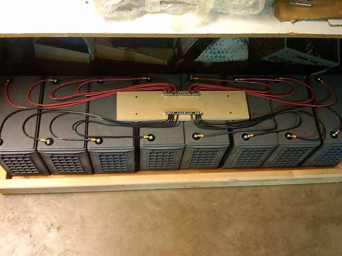
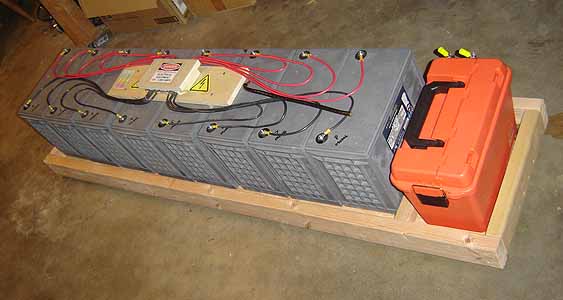
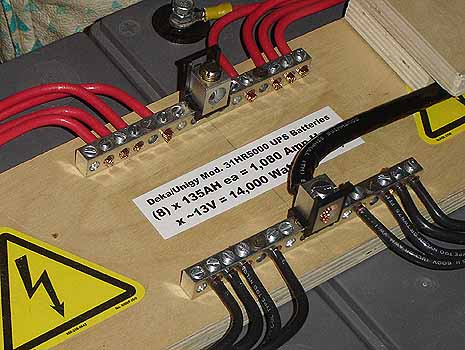
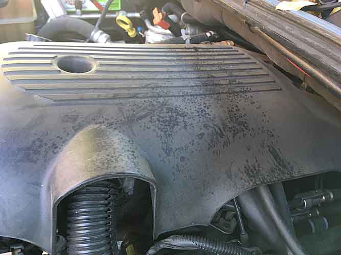
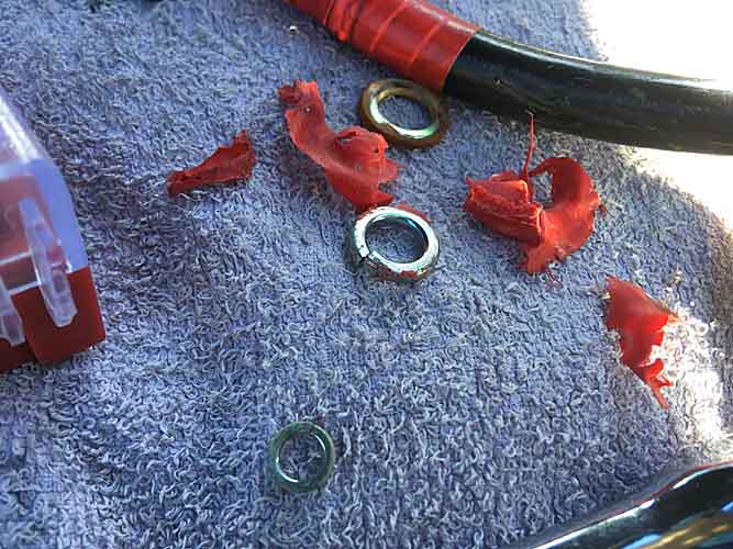
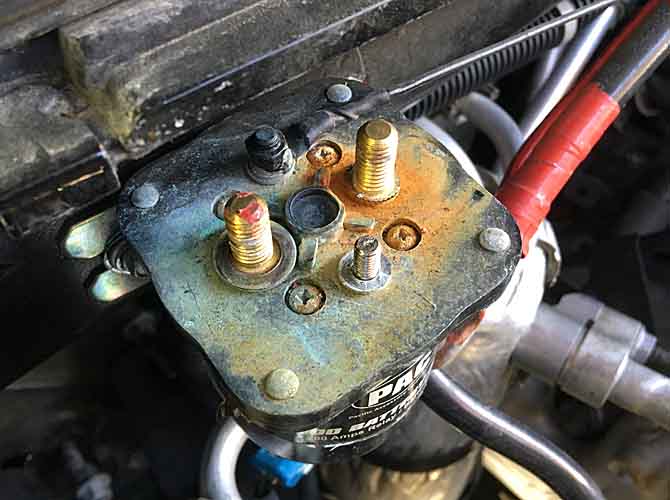
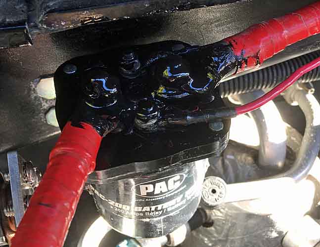
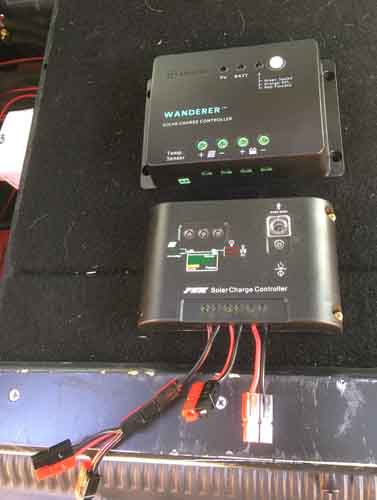
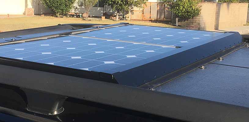
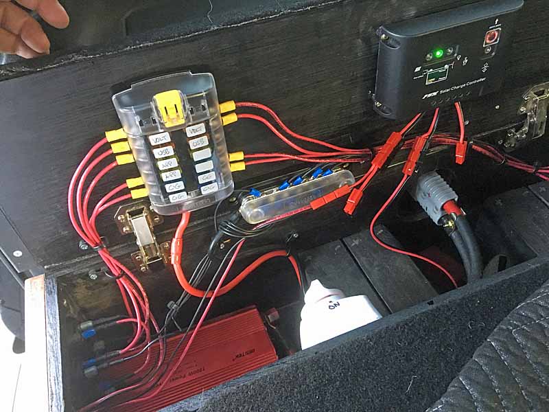
Random eye candy:

solarpanelmount87%20installed.jpg


solarpanelmount85%20installed.jpg


solarpanelmount28.jpg
solarpanelmount38.jpg
solarpanelmount06.jpg
 
Last edited:
We'd need more information to diagnose the issues, but here are some thoughts:
Your profile says you're from the LA area, so having the panels mounted flat, facing up shouldn't be too much of an issue in the summer, but the rest of the year, your panels' max output is reduced if you don't tilt the panels. I'm assuming you don't (despite the picture apparently showing the panels off the roof ;). On average, you can probably expect 75% of the rated max output:

100W / 18V x 0.75= 4A solar output...less from the PWM controller's output, but I'm ignoring that.

In the LA area, you get the equivalent of 5-6h of full sun each day, so let's say 5.5h x 4A = 22Ah. I don't know what your loads are, but if you are using the rule of thumb of never draining your Aux more than 50%, and your group 78 is rated at 50Ah, 22Ah wouldn't quite top it off in a day. I assume that the solenoid connects the batteries when the engine is running and/or the Aux voltage is higher than the start battery voltage, so the alternator should be contributing to charging Aux. If the alternator can get the battery to 80% state of charge, your solar capacity should be enough to top off the battery, but that assumes that there's good sun on the panels when the vehicle is not running. The other thing to consider is that your battery won't be pulling 4A as it gets closer to full charge, so the panels may require quite a bit of time in the sun.

It's a little hard to tell from your pictures, but it looks like the mounting frame for the panels is very close to the edge of the cells, and sticks up a bit over the surface of the cells. That means you could be getting partial shading a lot of the time, and a little bit of shading can dramatically reduce the solar panel's output.

The PWM controller is pretty crappy, like most inexpensive charge controllers. If you are seeing 14.4V on "the bus," you're either getting too much voltage drop in the wiring/connectors, or the controller is not configured optimally. Is there a setting for flooded lead acid batteries? That should push the charging voltage up to 14.6V, which can make a difference. The other concern is that that type of controller is likely pre-set to run the boost/absorb stage for 120 minutes, which may not be long enough. Essentially, you're not charging most of the day. The float voltage may be too low to keep up with parasitic or self-discharge, as well, if you're reading 13.2V. 13.6 is more common.

Another concern is the starter battery never getting over 12.25V. You're killing it. It's probably toast. Either there's a problem with the vehicle's charging system, or your infrequent trips and electric accessory use is draining the battery faster than you can charge it (my guess is the latter.) You should run a good, long equalizing charge on it...probably 2-3 days. Then fix the solar setup's issues so that it can charge along with Aux when the engine is off.

Lastly, using a starter battery for Aux is a sure way to sadness, no matter what you do.
 
I know you said you want to keep it cheap, but get something like this to monitor your Aux battery & solar charging. https://www.amazon.com/gp/product/B017BDQHE6/ref=oh_aui_search_detailpage?ie=UTF8&psc=1 Mount the shunt right at the battery. Or replace your charge controller with a EPsolar Viewstar VS1024BN PWM Solar Battery Charge Controller for 50 bucks. It has good adjustability and a display for voltage and current.

Also, get a hydrometer* to measure your batteries' state of charge. The only time a voltage reading will accurately tell you the state of charge is when there is NOTHING connected to it and it has been sitting for a few hours.

*I highly recommend the MidNite Solar Hydrovolt Battery Hydrometer. It has automatic temperature compensation, is self leveling, and is much more precise than the $9 hydrometers you get from the auto store. I bought a couple highly recommended cheap hydrometers over the years, and none of them had the precision and reproducibility to evaluate the state of charge with any confidence.
 
Thank you for the treatise on solar power, I'm sure people will find it useful. But it leaves my primary question unaddressed. Still trying to find out what battery voltage level attained that I ought to be seeing out of a generic PWM controller.
By most generic 'state of charge' charts it seems 12.6V is considered 100% charged and that's apparently what is happening with this controller. I had hoped for a bit more. I'm trying to determine if 'more' would be achieved by spending another $30-50 on a brand-name PWM controller. Not going to spend that if my net result is no change.

My no-name no-manual controller seems to be behaving as it ought. I'm getting a ~14.4V bulk charge in the morning hours, presumably a boost phase and by mid-afternoon I'm in what I perceive to be the float phase, with ~13.4V on the bus - and by bus I mean my Aux battery, the ~14' of 1/0 cabling running to my cargo area power module setup to the terminal lugs within it, where everything in the box is connected to. Fuse panel, large inverter (which is kept off and further isolated by a rotary marine-style cutoff switch) and the PWM controller. And also a voltmeter on a momentary switch.

I've had (4) dual-port panel-mount USB inverters in the vehicle for over a year. (2) on the factory / starter battery wiring and (2) on the power module in the back, running off the Aux.
The same afternoon of my posting this topic I replaced the center console USB inverter with a socket and a plug-in inverter which is left out until needed. The inverter in the high panel over the windshield (power for dash cam and windshield cell phone holder) is on a factory courtesy circuit whose power is killed 10mins after key removal. In the rear module I put in a panel switch to cut off power to the rear-facing inverter and pulled the fuse on the forward facing inverter. In my build it isn't typically accessible anyway.
So that's all those parasitic loads removed from the equation. Except that of the PWM controller itself, and the vehicle computers. I can't do anything about either of those. And parked in the street there isn't going to be any sort of float charge arrangement for the starter battery. In a couple months I'm buying another of the same battery and swapping things around and I don't really expect there to be much change in that Starter voltage situation after a week or so. I think that lowered voltage will be a reflection of inactivity and the vehicle's own drains, even with an otherwise fresh battery.

As for panel obscuration, I was already aware of those concerns and took some pains to design my mounting frame so that would not be an issue. The frame fore and aft is a couple inches larger than the panel and has bump-stops inside it to keep the panel in the proper position fore and aft such that the C-channel does not overlap or shade the cells themselves. And the sides of the mounting frame are shorter than the panel's own frame and do not overlap it at all. More detailed pictures and some design sketches are in my build thread. Most of my panel mounting frame details are on pgs8-9 of my build topic, in my sig below.
fresh pics in mid-day sun to follow shortly.

As for running a flooded automotive battery as my Aux, I am not accepting the 'common wisdom' about that. I'm not an ExPo Glamper, don't have a ARB fridge, blender, electric blanket, portable AC or much of anything in terms of electrical loads. All I really need from the Aux at night is some light. My 'power module' setup is there to provide a variety of power supply options in both DC and AC and various interfaces. It's there to re-charge or run small electronics primarily during the day.
And I deliberately chose to have battery commonality with the Starter battery, in case it unexpectedly fries when I'm out in the desert southwest. And I chose a national brand that I can get affordably replaced just about anywhere in the CONUS. Those are greater concerns to me than having an optimal deep-cycle for fixed-site camping for days on end. My days of doing that are decades behind me.
So the common wisdom of an optimal solar power system doesn't really apply to my circumstances and I am instead looking to use the elements of such systems design to suit my uses and goals, rather than the other way around of strictly adhering to an ideal system, at a much higher financial cost. I've got too many interests, hobbies and demands on my wallet to do the latter, anyway.

So thanks for your informational inputs and here's a bump hoping somebody here has a Renology Wanderer PWM and let us know what voltage it can keep their battery(ies) at.


eta right now I'm measuring 12.19 at the Starter, despite a 300mi+ high speed round trip on Thanksgiving, been parked for 17hrs+. I'm reading 13.51 at the Aux terminals, with the solar connected (and a fluctuating 13.4/13.5 at that rear voltmeter, doesn't seem like there's much voltage drop at all with that 1/0 cable). Presumably in 'float'. I've been checking voltage readings frequently since I mounted the panel and controller, partly to see that the controller was working ok, since I bought it used / third-hand. But also to get a feel for the baseline of things. And I've also been checking levels at the battery terminals around 8-10pm. Figuring that's sufficiently 'at rest' to give an accurate 'state of charge' reading.

eta2 I've also got a bit of corrosion-looking crud atop my connecting solenoid. But probing around with a multimeter I can't find any sign of a voltage leak. But I'm going to strip the liquid electrical tape off those connections and scrub it all down with a baking soda solution, clean it up and coat the top between the terminal and wiring posts with dielectric grease, before reconnecting everything.
I'll likely also temporarily disconnect the 1/0 cable that bridges my Starter battery to that solenoid to rule that out as a drain. See if the vehicle's charging system brings that battery higher on its own.

what I had hoped would be happening is the solar would keep the Aux topped and every time I drive the vehicle / the solenoid is engaged and there's some 'leveling' between the batteries, bringing up the Starter. For all I know right now I could have an alternator regulator problem. I was not regularly checking / comparing battery voltages before I installed the solar. I was occasionally hittign the rear voltmeter and seeing 12.6 on the Aux so my presumption was vehicle and combined charging was working fine. Which ought to have meant the starter was at 12.6 too.
I may very well have a bad cell in that year-old battery. In which case I'll be getting a pro-rated replacement out of Costco.
And the bulb on my aged cheap hydrometer won't hold suction, have to get a replacement
 
Last edited:
The newer wander specifies 14.6V for 2 hours.
https://www.renogy.com/template/files/Manuals/Wanderer Li (1).pdf

IIRC the older version maxed out at 14.4V.

Regardless, I think 2 hours is too short to complete the absorb phase. 3 hours would be the minimum in my experience.

The fully programmable controllers allow any combination of time and voltage. Many can specify the return amps for fully charged as a primary or alternate absorb termination option.
 
Battery resting voltage has nothing to do with the solar charge controller, it has to do with the battery. If the charging system is getting the battery topped off, then it should be resting at manufacturer's spec for that battery.

It doesn't really matter if the controller bulks to 14.4v or14.6v, or absorbs at 14.2v. A couple of tenths of a volt difference just affects the time it takes for the battery to fully absorb to 100% saturation.

Right now is dead of winter. Even in L.A. the sun is not at an optimum angle and a flat-mount panel is at a disadvantage to start with. I'm in L.A; I tested my flat-mounted 300w panel last week by drawing down the battery a bit. Even during peak hours, the angle was so bad that it only averaged about 150w. And that's with an MPPT controller.

With a 100w panel and PWM controller...I dunno...40w-50w during peak hours?


But maybe it's getting the job done. What is the manufacturer's spec for resting voltage on that battery? If it's 12.6v then it's working.
 
yep, that's the math anyway, should be a little better. The panel label promises 100W/17.5V/5.44A (which is 95W at peak)
I got the same indicated peak voltage out of the panel setup properly angled on the ground or flat in the mount, 14.3-14.4 thru the morning and midday. Then ~13.3/13.4 in the afternoon hours when it's presumably in float mode.

solarpanelmount81%20ground%20test.jpg


I was getting around 12.3-12.4 at the rear voltmeter on the Aux, before the solar hookup. It took about 3-4days after I went live with the solar system before I was getting a consistent 12.6V indicated on the Aux, which I attribute to the PWM. I'm getting negligible voltage drop between the readings at the Aux terminals up front and at the terminals in the rear of the vehicle on their other end of the 1/0 cabling.
I'd say it's working as designed but that I've got a separate unrelated problem on the Starter / Factory side of things.

And I do not recall EVER getting the two batteries - ETA at rest disconnected via solenoid - to measure within .2V of each other. The Aux always reading higher and even when it had more of a known parasitic load on it. Might just be a 'better' individual battery. Combined and vehicle running I read the same regulator output voltage everywhere.

I've got some crud to clean off the top of the bridging solenoid and some dialectric grease to apply, in an attempt to rule out any parasitic voltage loss that way and the other thing I can do while I wait for my Amazon Black Friday order to arrive (with my new hydrometer) is physically swap my batteries and see what ensues. Or at least take my Starter battery out and put a thorough charge on it and see it will hold at higher than 12.25V. I could very well have a bad / weak cell in it. I took the caps off both to check fluid levels and peer inside with a flashlight two days ago and didn't see anything out of the ordinary. A hydrometer and a load test are in the very near future.

Here's the only pic I have handy that shows some of the corrosion-looking crud atop the plastic housing of my bridging solenoid. I haven't been overly concerned with it to date as we have hard water here and it's pretty much right under the join of hood and cowl and no doubt gets soapy water on it. But like I said, I'm going to rectify that, probably tomorrow. And maybe rig some sort of flap at the cowl lip so water can't drip on it.

blueseaAux4.jpg


So I think I'm going to pull the starter battery tomorrow and put it on my trusty old Sears charger and see what happens. And while its charging I'll swap the Aux to the starter position and clean up those solenoid connections. I might just leave the Aux charging cable and solar disconnected for a couple days and see what happens to the voltage of the Aux-as-Starter in isolation. And same for the Starter battery, see what happens to it as it sits in the garage for a couple days. 3-4days I'll have some data by the time the hydrometer arrives. And if its cells all test ok I'll put it in the Aux slot and reconnect everything and see how it goes. Or still leave the starter battery out and just hook up the solenoid to the Aux-as-Starter and see if .4V disappears over a couple more days.
Then after that if it still holds a proper higher voltage, I shrug and reconnect the Starter-as-Aux. And again look for changes.
And after that install the Renology Wanderer I also just ordered today. They cut the price another 15% so at $26 why not?

Just going to have to change one variable at a time until I find the issue / disparity. With a working charging system, good cells, and a 200A solenoid and long drives when I do, the resting voltage on these like batteries really ought to be very close. Much closer than I've been getting.

The only other option that would help this setup might be an ACR-type combiner, such that the solar power also gets doled out to the Starter. But that seems problematic in other topics discussing such arrangements. And especially the way I have things arranged, with the solar input being at the end fo the branching cable to the rear, coming off (backfeeding) the Aux. An ACR would only be seeing a higher voltage on the Aux side and not on its 'supply' / input terminal. I don't think they'd dump juice from Aux to Start, I think they'd only shunt 'supply' to whichever battery is lower. But I'm not up to speed on their full operations, I ruled them out long ago based on cost.

One of these days I'll properly diagram what I've done, a la the '$50' diagrams, make it easier to convey all this. And I can also lay out future expansions. I intend to eventually have a receiver-hitch-mounted winch and Anderson SB350 couplers at front and rear bumpers for plugging it in. It's why I went with a 1/0 cable backbone to my rear power module. Eventually it will have a branch/ extension on it to feed a rear-mounted winch.

I'm also modifying my old heavy set of jumper cables so one end is attached via the same couplers, that way I can pull that end off and just jack it in at the bumpers like a military slave cable connection. And make it possible to jump folks from the rear of my vehicle.
 
Last edited:
A PWM just connects the solar to the battery until the battery voltage reaches a set point - say 14.4v - and then "pulses" (quickly connecting/disconnecting) the solar to the battery to hold the voltage at a set level.

If the battery voltage is quickly rising to the set point, then the battery wasn't drawn down much. So it's likely that the aux is getting charged and resting at 12.6v is proper.

A couple other points...

A proper ACR is dual sensing - if the voltage rises on either side it engages. Of course, once it's engaged there's just one big battery so the voltage it reads is the same on both sides. Check out the Samlex ACR-160. Good ACR for around $100.


The idea that your batteries would equalize when connected while driving is false. They will both be brought up to whatever voltage the voltage regulator is operating the alternator at. Power would flow from alternator into each battery, but not from battery to battery.


The idea that voltage drops from one end of the circuit to the other end is also false. A circuit is a circle and a circle has no ends. If voltage drops it drops around the entire loop.


Voltage drop is a function of load. If there is only a couple of amps flowing through a large wire, there won't be any significant voltage drop. Takes a high amp flow to induce a voltage drop on a big wire.

But you wouldn't be able to measure the voltage drop by sticking a meter's probes at two different points on a circle anyway.
 
well that confuses me more, because when the solenoid is engaged wouldn't he disparate charge states on the two connected batteries try to 'level'. How would they maintain different charge levels if they are connected. Some time ago I was reading about keeping / maintaining solar battery banks and the various wiring topologies for connecting an array of multiple batteries to either equalize the load on them all or to maintain them all. One of those topologies was a star-parallel, with each of the multiple batteries connected to a bus bar, all (+) to one bar, all (-) to another, with a float charger / maintainer hooked to the bus bars. I did it with (8) Deka SLAs and it seemed to work.

battery wiring production 5 090920.jpg
batterybank100113.jpg
batteryUPSbus.jpg

batteryUPSbuss.jpg


so when I went to the simple solution of a keyed solenoid as a combiner I figured the same thing would be happening when there was a disparate voltage level in the two batteries. I still don't understand why that wouldn't be the case, regardless of what the alternator-regulator is doing. I mean the batteries are designed ot be the same capacitance, but one has a lower state of charge than they other, so they ought to

And I can't really see it happening the way I have things wired, the keyed source / trigger for the solenoid doesn't seem to be active until I start the vehicle. Which isn't really what I want, anyway. If I've somehow drained the Starter battery too low to crank the vehicle I cannot just turn the key and gain power from the Aux to start the vehicle. I have to either jumper that pole on the solenoid from the Aux or self-jump, battery to battery.
And the regulator ought to just 'see' that there's a need for charging. It doesnt now or care which battery is hungry, all it knows is power flows.

But now I'm envisioning another problem. Maybe when I'm running the vehicle, the solenoid does its thing and then suddenly the 14.4V of the PWM is throughout the bus, similar / same to the voltage regulator's output, such that it doesn't think it needs to do anything. But I guess i'm mixing up voltage levels with capacitance(?)? The regulator has an available output of 14.4?7? @130A.

(to be confusingly continued...)

/
Right now I have my charger on the Starter battery IN the vehicle. I haven't pulled the battery or disconnected or rectified anything else. And forgot to measure the overnight resting voltage before I moved it into the driveway. The charger has been bounding in and out of 'FULL' for about an hour, after about an hour of charging. What passes for an 'absorption' charge with my charger. Trying to nudge the battery up to a steady 'FULL' indication.

I found another parasitic drain on the Starter. It seems the OBDII port is always hot. I've been inadvertently leaving my Panlong Bluetooth OBDII data transmitter plugged in, as I've been messing around with the Torque app on my android tablet on road trips lately, messing with other things. I never realized the power on that port stayed on. It might not, might only be coming on when I cut the alarm and open the door. But without a key turn I noticed today that the transmitter's LED was lit. So I've pulled that out, too.

I was also repeatedly checking voltage on the Aux bus / solar PWM activity throughout the morning and was seeing 14.4 on that side of the solenoid up to about Noon, whereupon it dropped to ~13.4/5. Measured 13.56V at the Aux battery itself. I am fairly sure that this is the PWM moving into 'float' after bulk and absorption. Still full light on the panel, parked in the driveway.

That's where things stood up to about an hour ago when I finished my suburban yard work chores. I think after my charger goes full 'FULL' and ceases visible charging indications I'll pull it and disconnect the solar AND the PWM, briefly fire up the vehicle for regulator readings and spot checking indicated voltages at several places. And then shut it down and leave it sit to see what happens after the batteries settle down, and thru to the morning.

eta 1400PST my charger is pulsing to ~14.25 and dropping to 12.96 - which I presume is the excited state of charge of the Starter battery - on about a 5 second cycle. Aux terminal reading is 13.51V. Rear power module terminal lugs at the other end of the 1/0 cables also read 13.51. These are the same lugs the battery feed from teh PWM are connected to, so that's most likely the float charge from it. The rear panel-mounted voltmeter - connected to the fuse panel which is itself connected to those rear terminal lugs - reads 13.4. So I figure it is reading something like 0.1V lower.

And lastly the PWM itself has a solid green solar panel LED indicator and a slow blink on the PWM LED. Which in the Renology's manual indicates low output on the panel and a float charge being put on the battery. Which sort of goes together. I could unlatch and elevate the panel right now to rule out any issue there. The panel output OUGHT to be low, if there's nowhere for the juice to go, aka '[Aux] battery's full, yo'. Which is should be. I'm gonna go mess with that panel and see what happens. Got about 2hrs more useful sunlight if I aim the panel right. But the wind is gusting around here so can't leave it sitting that way. Will move it just enough to see if it makes a difference in the PWM indication. Which I don't expect it to, give the state of the battery. No report means no change.
 
Last edited:
well that confuses me more, because when the solenoid is engaged wouldn't he disparate charge states on the two connected batteries try to 'level'.

They won't try to level when the engine is running because the alternator is supplying the system with a power injection that has a higher potential voltage than either of the batteries. So power flows from the alternator (supply) into the "bus" and since the batteries have a lower potential voltage than the supply, they each suck or absorb power from the bus as they can, depending on their own voltage/state of charge/resistance.

So basically, the alternator is pushing to bring the batteries up to its level. The batteries aren't trying to level with each other, they are each trying to level with the alternator.


How would they maintain different charge levels if they are connected.

They don't maintain different charge levels. They each have their own state of charge. You supply power via the alternator, and each absorbs what it can. Ultimately, both will reach the voltage that the voltage regulator is operating the alternator at. But that will be a surface charge. It will take some time at that voltage for the battery to fully absorb. Depending on state of charge, one might saturate quickly, and one slowly.

In other words, they might both reach the same voltage with the engine running, but that doesn't mean they are both at the same state of charge. You'd have to shut off the engine, wait a couple of hours and test them to see what their state of charge is.


Some time ago I was reading about keeping / maintaining solar battery banks and the various wiring topologies for connecting an array of multiple batteries to either equalize the load on them all or to maintain them all. One of those topologies was a star-parallel, with each of the multiple batteries connected to a bus bar, all (+) to one bar, all (-) to another, with a float charger / maintainer hooked to the bus bars. I did it with (8) Deka SLAs and it seemed to work.

battery wiring production 5 090920.jpg
batterybank100113.jpg
batteryUPSbus.jpg

batteryUPSbuss.jpg


so when I went to the simple solution of a keyed solenoid as a combiner I figured the same thing would be happening when there was a disparate voltage level in the two batteries. I still don't understand why that wouldn't be the case, regardless of what the alternator-regulator is doing. I mean the batteries are designed ot be the same capacitance, but one has a lower state of charge than they other, so they ought to

The star topology isn't about leveling. It's about having as close as possible flow through each of the batteries. Whether operating at charge or discharge, any battery/wiring with a lower resistance than the others will do more work and wear out sooner. The various wiring topologies are just different schemes to try to keep the flow through each battery/string balanced.

But again, the batteries will level - as long as there is nothing else going on...such as a supply with a higher voltage potential injecting power into the system, or a load dragging watts out of the system.


And I can't really see it happening the way I have things wired, the keyed source / trigger for the solenoid doesn't seem to be active until I start the vehicle. Which isn't really what I want, anyway. If I've somehow drained the Starter battery too low to crank the vehicle I cannot just turn the key and gain power from the Aux to start the vehicle. I have to either jumper that pole on the solenoid from the Aux or self-jump, battery to battery.

That's a normal issue with a dumb solenoid. But you'd have to run the engine battery really dead to have that issue. Even a couple volts still in the engine battery will often be enough to engage the solenoid. So even if the battery is too low to start the truck, it might still engage the solenoid.


And the regulator ought to just 'see' that there's a need for charging. It doesnt now or care which battery is hungry, all it knows is power flows.

The regulator doesn't see a need for charging. It doesn't know that power flows. These are anthropomorphisms that don't apply (but are pretty common).

The regulator maintains a bus voltage. If the voltage is lower than it should be, it engages the field coil of the alternator. If the voltage is where it should be, it disengages the field coil.

Loads on the bus - such as lights or batteries absorbing power - will suck power out of the system, pulling down the voltage.


But now I'm envisioning another problem. Maybe when I'm running the vehicle, the solenoid does its thing and then suddenly the 14.4V of the PWM is throughout the bus, similar / same to the voltage regulator's output, such that it doesn't think it needs to do anything.

Again, anthropomorphism. It doesn't think.

You have to consider resistance vs. potential. Potential is probably the most important word in electricity, but hardly anyone thinks in terms of potential. Think of it as the opposite of resistance. Your alternator might have a potential to reach say 300v (no, not a typo, I said three-hundred volts). And your solar might have the potential to reach say 17v. But each has its own voltage regulator which will limit the voltage to say, 14.4v.

Now suppose you have a battery at 12.5v and it's going to suck up power from the bus, and you have both alternator and solar supplying the bus. Where does the power come from to feed the battery - alternator, or solar?

It depends one which one has the lesser resistance/higher potential. If the alternator has the lesser resistance/higher potential, then the power will flow from it into the bus more readily than it will flow from the solar into the bus. And vice versa if the solar has the lesser resistance/higher potential.

But it doesn't actually matter. Either way is fine. If the solar had the lesser resistance/higher potential and could supply say 5a of power, then the first 5a being drawn out of the bus would come from the solar, once the load on the bus exceeded the 5a the solar could supply, the solar would be supplying 5a and the alternator would be supplying the rest.

In the opposite case, if the alternator has the lower resistance/higher potential, then the first 130a of load would be getting supplied by power from the alternator, and anything over that - up to 5a - would be supplied by the solar.

This is why multiple charging systems don't "butt heads" or "fool each other" (more anthropomorphism). Just hook them up and physics will decide where the power flows from and to where.


[Stopping here. Getting a warning about the 10k character limit.]
 
I found another parasitic drain on the Starter. It seems the OBDII port is always hot. I've been inadvertently leaving my Panlong Bluetooth OBDII data transmitter plugged in, as I've been messing around with the Torque app on my android tablet on road trips lately, messing with other things. I never realized the power on that port stayed on. It might not, might only be coming on when I cut the alarm and open the door. But without a key turn I noticed today that the transmitter's LED was lit. So I've pulled that out, too.

Yea, my Kiwi3 OBD bluetooth dongle is hot all the time on the '99 Ford van I bought this year. I have to remember to unplug it when I'm not using it.


I was also repeatedly checking voltage on the Aux bus / solar PWM activity throughout the morning and was seeing 14.4 on that side of the solenoid up to about Noon, whereupon it dropped to ~13.4/5. Measured 13.56V at the Aux battery itself. I am fairly sure that this is the PWM moving into 'float' after bulk and absorption. Still full light on the panel, parked in the driveway.

Yup, float.


eta 1400PST my charger is pulsing to ~14.25 and dropping to 12.96 - which I presume is the excited state of charge of the Starter battery - on about a 5 second cycle. Aux terminal reading is 13.51V. Rear power module terminal lugs at the other end of the 1/0 cables also read 13.51. These are the same lugs the battery feed from teh PWM are connected to, so that's most likely the float charge from it.

Well, if the engine is off/solenoid disengaged, but the solar is supplying a float voltage, then the entire aux side bus will be at the solar float voltage.


The rear panel-mounted voltmeter - connected to the fuse panel which is itself connected to those rear terminal lugs - reads 13.4. So I figure it is reading something like 0.1V lower.

Yea, voltmeters aren't all made by Fluke. I've got a couple that read wayyy off.


And lastly the PWM itself has a solid green solar panel LED indicator and a slow blink on the PWM LED. Which in the Renology's manual indicates low output on the panel and a float charge being put on the battery. Which sort of goes together. I could unlatch and elevate the panel right now to rule out any issue there. The panel output OUGHT to be low, if there's nowhere for the juice to go, aka '[Aux] battery's full, yo'. Which is should be. I'm gonna go mess with that panel and see what happens. Got about 2hrs more useful sunlight if I aim the panel right. But the wind is gusting around here so can't leave it sitting that way. Will move it just enough to see if it makes a difference in the PWM indication. Which I don't expect it to, give the state of the battery. No report means no change.

Yes, that is correct. If the battery is full, the solar will only produce enough power to keep the battery (or the entire aux bus) at float voltage. If that takes 0.2 amps, then that is all that will be produced, even if by my 300w panel in full sunlight - or Hoover Dam. Hoover Dam can potentially produce 2,000 megawatts, but if the only thing hooked up to it is a 40w bulb, then it will only produce 40w, even if the turbines are spinning full speed.

Electricity doesn't actually exist until there is something trying to use it. Until there is a load, electricity is just a potential. It's magically created at the moment it is needed.
 
Last edited:
Good discussion. I often read (and commit myself) potential or voltage described as pressure, and other fluid dynamics concepts poorly applied to electricity. There's some conceptual overlap, particularly with regard to wire and pipe sizing, but they are not the same. Sometimes the terms help sometime they confuse the issue.

Last night's and this morning's battery readings pretty much have me thinking I've got a bad cell in my year-old starter battery. 5pm-ish I pulled the charger from it and disconnected the solar and its controller from the aux side of the solenoid. No inputs, all the added loads I can find were removed. By 8pm the starter battery had already dropped from 12.72 to 12.4V, while the identical (but 2yr old) Aux battery had only dropped from 12.78 to 12.74. 11am today the Starter was back down to 12.21 while the Aux held 12.71.
It's new enough I should be able to get a free/full replacement.
I'm going to wait for my new hydrometer so I can confirm the bad cell.
And today I'm going to detach the cable connecting that Starter battery to the combiner solenoid and charge the battery again, do another overnight beeld-down to rule out that setup as the drain.
I've also got some mouse / rat sign on the top engine shroud, little paw prints etc. Maybe a rodent has chewed some wires somewhere.

For diagnostic purposes I could still just swap the batteries. And see if the overnight depletion follows the battery or is tied to a physical location.
I think I'll go ahead and do that today. I want to scour that solenoid today anyway and it will be a few more days before the hydrometer comes, anyway.
And I've got some home remodeling / wiring changes to get done early this week, so it's not like the vehicle battery issue is pressing. I'd rather not go anywhere near Costco this holiday shopping weekend, anyway.
And swapping things, I can have the faulty battery already dismounted when I do go and get the swap done in a jiffy.
 
I've just done a physical swap of the batteries and took the opportunity to clean up the solenoid connections too. That violates basic troubleshooting, changed more than one variable at the same time. But if my problem is truly a bad cell in teh starter battery it won't matter.
I've still got the solar and PWM disconnected and have the charger topping off the Starter battery again, now mounted in the Aux position. So in a few hours I'll start monitoring battery voltages into the night and overnighit and see what is up with that. wot? watt?

No good dirty rat sign

batterytrouble10 rat sign.jpg


'Liquid Electrical Tape' is good stuff. But it takes something like a dental pic to readily remove it. I slathered it over the lugs of the solenoid mostly as a guard against incidental tool contact with the connections.

batterytrouble11 liquid tape debris.jpg


The mess on the top of the solenoid. The rust-looking staining is well, rust. 'Some idiot' used a steel washer under the cable lug. Have to round up a batch of copper washers and do it up right. Or better yet put a thin nut on first, down to the bottom of the stud, then sandwich the cable lug between copper washers.

batterytrouble12 solenoid corrosion.jpg


I scrubbed that clean with a baking soda solution and a toothbrush. Beware of splattering that all over. When it was clean and dry I used another brush to apply a coating of dielectric grease to the top of the solenoid housing, taking care not to get any on the terminal stud / cable contact areas.

batterytrouble13 solenoid greased.jpg


And my red liquid tape had turned, so I slathered some black on it instead. Should have skipped it in the short term, needing the aforementioned copper washers. But I'm not venturing out this shopping weekend for anything.

batterytrouble14 coated.jpg


So, a couple hours more and I'll pull the charger and spot check voltages ever couple hours and see what we get overnight.
If it's a low cell the problem should move with that battery, if it's a wiring fault or unknown parasitic load, we'll see the former Aux battery plummet overnight.
 
Last edited:
Well last night and first thing this morning it seemed the problem is the position and not the battery as overnight the Aux-as-Starter went down to 12.51 while the Starter-as-Aux held to 12.61. So the battery in the starter position still declined, but not as much.
Then I ran some morning errands about town and come home to a cheery identical surface charge on both of 12.72 and for the rest of the day they stayed within .02V of each other as they settled down.
They're in another overnight cycle / test now. Vehicle not driven since 1045 this morning. No added juice to either. May very well have been a voltage leak via the crud on top of the solenoid. Or might still have a minor wiring fault on the Starter / Factory side of things. But I no longer think it's the battery.
Will still run the hydrometer tests when it comes.
 
Well the Renogy controller came today and is installed. Seems to be operating 0.2V higher than the no-name controller. Low voltage at the Starter location continues. I'll start probing all the fused circuits this weekend, trying to find the culprit.

batterytrouble16 renogy.jpg
 

Forum statistics

Threads
190,882
Messages
2,932,871
Members
234,698
Latest member
OchoSolo
Top