cobes
New member
Hey folks,
Trying to get an idea on how to troubleshoot an issue. New to solar and this is my first time using a multimeter too so appreciate some help. I just got a new camper, and it has be pre-wired for solar. The first time I hooked up my panel, and then went into the camper to plug the input Anderson connector into my Goalzero, I was not getting any input power.
Some details on equipment.
- Merlin 170 Watt panel. Used multimeter and read 23.4 watts and 7.4 amps directly from the panel.
- Goalzero Yeti 1500x.
- Camper is a Vagabond Drifter, with wiring from the outside to in.
I've already tried stepping back to try to get a reading at every connector. And with the panel plugged into the MC4 connectors on the roof, I was not able to get that same reading at the first junction which is an Anderson connector(see attachment).
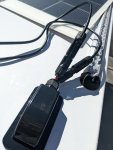
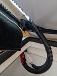
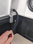
Pictures are of the roof where the 2 MC4s meet, the first change inside of that same corner about 10" later, and then the exit and input Anderson connector in the bed. As far as I can tell, nothing has been switched. Red connectors are matched with red wires. The MC4 connectors themselves on the roof have the opposite polarity than the wire suggests, but I assume that's just the connector they had on hand and don't really have a way of testing that I don't think.
The box on the roof that passes the cable through I don't know much about, I don't think there's any connectors inside. The negative MC4 off the panel was not connecting perfectly to the negative MC4 on the camper. The latches didn't lock completely, so I filed down the end of the MC4 to get it to clear and catch but still no luck. I'm wondering if the MC4 specs are slightly off and the pins inside aren't properly meeting?
So not sure how to go about finding the issue. Any help would be greatly appreciated. Can give more details and pics if needed.
Thanks
Trying to get an idea on how to troubleshoot an issue. New to solar and this is my first time using a multimeter too so appreciate some help. I just got a new camper, and it has be pre-wired for solar. The first time I hooked up my panel, and then went into the camper to plug the input Anderson connector into my Goalzero, I was not getting any input power.
Some details on equipment.
- Merlin 170 Watt panel. Used multimeter and read 23.4 watts and 7.4 amps directly from the panel.
- Goalzero Yeti 1500x.
- Camper is a Vagabond Drifter, with wiring from the outside to in.
I've already tried stepping back to try to get a reading at every connector. And with the panel plugged into the MC4 connectors on the roof, I was not able to get that same reading at the first junction which is an Anderson connector(see attachment).
Pictures are of the roof where the 2 MC4s meet, the first change inside of that same corner about 10" later, and then the exit and input Anderson connector in the bed. As far as I can tell, nothing has been switched. Red connectors are matched with red wires. The MC4 connectors themselves on the roof have the opposite polarity than the wire suggests, but I assume that's just the connector they had on hand and don't really have a way of testing that I don't think.
The box on the roof that passes the cable through I don't know much about, I don't think there's any connectors inside. The negative MC4 off the panel was not connecting perfectly to the negative MC4 on the camper. The latches didn't lock completely, so I filed down the end of the MC4 to get it to clear and catch but still no luck. I'm wondering if the MC4 specs are slightly off and the pins inside aren't properly meeting?
So not sure how to go about finding the issue. Any help would be greatly appreciated. Can give more details and pics if needed.
Thanks