Does anyone have experience wiring their Morningstar Sunsaver to an aux fuse block. I really want to install a 100 watt panel on the roof with a Sunsaver to my aux fuse block from my second battery. I guess my big question is does the Sunsaver need to be wired to the load or can it just go the second battery and that's it?
You are using an out of date browser. It may not display this or other websites correctly.
You should upgrade or use an alternative browser.
You should upgrade or use an alternative browser.
Wiring solar to aux fuse block?
- Thread starter badtoytrd
- Start date
Tigglebitties
Adventurer
Subbed. I've got the same question. I know you need some kinda diode to keep it from flowing to the panels but I'm curious
jonyjoe101
Adventurer
Yes you can connect the sunsaver wires that say "battery" directly to the battery or a fuse box that has wires going to the battery. The controller has to sense the battery voltage to know if it has to bulk or float the battery. You dont need any diodes which will block the controller from sensing the battery condition. The panels themselves have built-in diodes.
all solar charge controllers get there power to operate directly from the battery, they wont work unless they receive some sort of power to activate the circuits. The controller need to know the condition of the battery before they allow the solar panel to produce power. The directions always tell you to connect the battery first then the solar panel for proper operation.
You can disregard the load out of the controller because they are limited on how much amps they can deliver and some shut down if the voltage goes too high (example sun comes out of the clouds suddenly). All my accesories are connected to my fusebox which is connected directly to the battery.
To keep it simple the charge controller is just like any battery charger, to charge your aux battery just connect the controller "battery" wires where you normally charge that battery from and you would be good to go.
Yes you can connect the sunsaver wires that say "battery" directly to the battery or a fuse box that has wires going to the battery. The controller has to sense the battery voltage to know if it has to bulk or float the battery. You dont need any diodes which will block the controller from sensing the battery condition. The panels themselves have built-in diodes.
all solar charge controllers get there power to operate directly from the battery, they wont work unless they receive some sort of power to activate the circuits. The controller need to know the condition of the battery before they allow the solar panel to produce power. The directions always tell you to connect the battery first then the solar panel for proper operation.
You can disregard the load out of the controller because they are limited on how much amps they can deliver and some shut down if the voltage goes too high (example sun comes out of the clouds suddenly). All my accesories are connected to my fusebox which is connected directly to the battery.
To keep it simple the charge controller is just like any battery charger, to charge your aux battery just connect the controller "battery" wires where you normally charge that battery from and you would be good to go.
Any idea how this will affect national luna dual battery kit?
dwh
Tail-End Charlie
Subbed. I've got the same question. I know you need some kinda diode to keep it from flowing to the panels but I'm curious
Nah. That's only if you connect the solar panel directly to a battery without a charge controller in the loop. Then yea, you need to prevent back feed because a solar cell will make power when there is enough light on it, and will become a radiant heating element when there isn't enough light.
Any charge controller has two primary purposes - prevent back feed to the panels, and prevent battery overcharging, which can happen without a charge controller since the solar could push the battery as high as 15v-22v depending on the panel. All the other functionality it might have is just icing on the cake.
To the OP,
Yes, you can connect the battery outputs from the charge controller to the aux fuse block. If you have a spare fuse slot, then you can use that. Power doesn't *have to* only come out from that fuse block, you can also feed it in. By wiring the charge controller + to a fuse slot, you get an easy way to have a fuse in between the solar and the aux fuse block.
Power will feed in through that fuse into the fuse block and then back to the battery.
Or, you can connect the charge controller's output to the wires that feed into the fuse block from the battery. If you do that, then you should add a fuse between the charge controller and the fuse block.
Or, you can connect the charge controller's output directly to the battery. Again, put a fuse in that run of wire.
Don't connect the load output on your charge controller to anything. That's a low-voltage disconnect (LVD) and is meant to turn off something when the battery gets low to prevent the battery from being totally drained.
You might want to use it for something like a radio, just to make sure that the radio won't totally drain the battery. If you did that, again, stick a fuse in the line between the LVD and the radio.
CaliMobber
Adventurer
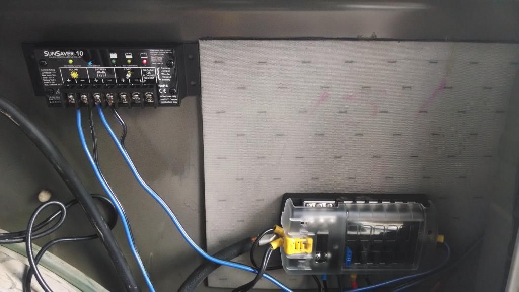
Lol pretty funny you ask, I basically did that exact thing a few days ago. 85w panel to sun savor to blue sea fuse box that feeds to the battery. It does not matter what battery is connected to, wont hurt anything.
Just make make sure if you charge controller is far from the battery you are connected with large wire. I prefer to be with in a foot or so but I cant do it with out running new larger wire so I just use my 4 to 6 gauge wire in the back and it seems to be large enough to prevent voltage loss.
Just make make sure if you charge controller is far from the battery you are connected with large wire. I prefer to be with in a foot or so but I cant do it with out running new larger wire so I just use my 4 to 6 gauge wire in the back and it seems to be large enough to prevent voltage loss.

dwh
Tail-End Charlie
I prefer to be with in a foot or so but I cant do it with out running new larger wire so I just use my 4 to 6 gauge wire in the back and it seems to be large enough to prevent voltage loss.
Voltage drop is not a big deal on a charging circuit. Voltage drop is a function of the amp load - the higher the load, the more the voltage drop. But when charging, as the battery voltage rises, the amps flowing goes down, and so does the voltage drop. Ultimately, the amps flowing is almost nil, and so is the voltage drop, so oversize wire isn't really needed.
Of course, the opposite happens when running loads from a battery - as the battery voltage goes down, the amps goes up, and so does the voltage drop. So you usually want oversize wire on a heavy load, like an inverter, running from a battery.
CaliMobber
Adventurer
Voltage drop is not a big deal on a charging circuit. Voltage drop is a function of the amp load - the higher the load, the more the voltage drop. But when charging, as the battery voltage rises, the amps flowing goes down, and so does the voltage drop. Ultimately, the amps flowing is almost nil, and so is the voltage drop, so oversize wire isn't really needed.
Of course, the opposite happens when running loads from a battery - as the battery voltage goes down, the amps goes up, and so does the voltage drop. So you usually want oversize wire on a heavy load, like an inverter, running from a battery.
Voltage drop has a HUGE issue. Imagine you batteries need 14.8volts to be fully topped off. Now imagine that charge controller is 10ft away with bad wiring and has a voltage drop of 1v.
So now the charge controller is charging at 14.8v to top off the batteries but since the voltage drops 1v the batteries are only seeing 13.8v. they will never get topped up even though the controller thinks they got what they needed. voltage is all about pressure and how much pressure it needs to push in more amps.
Maybe you read my post wrong because I know you understand charging as I do, yes volts/amps goes back and forth Amps * Volts = Watts
dwh
Tail-End Charlie
Voltage drop has a HUGE issue. Imagine you batteries need 14.8volts to be fully topped off. Now imagine that charge controller is 10ft away with bad wiring and has a voltage drop of 1v.
So now the charge controller is charging at 14.8v to top off the batteries but since the voltage drops 1v the batteries are only seeing 13.8v. they will never get topped up even though the controller thinks they got what they needed. voltage is all about pressure and how much pressure it needs to push in more amps.
Maybe you read my post wrong because I know you understand charging as I do, yes volts/amps goes back and forth Amps * Volts = Watts
No, I think you read my post wrong. What you just said is a textbook illustration of why I said it - many people don't actually understand voltage drop.
Read it again...
Voltage drop is not a big deal on a charging circuit. Voltage drop is a function of the amp load - the higher the load, the more the voltage drop. But when charging, as the battery voltage rises, the amps flowing goes down, and so does the voltage drop. Ultimately, the amps flowing is almost nil, and so is the voltage drop, so oversize wire isn't really needed.
Of course, the opposite happens when running loads from a battery - as the battery voltage goes down, the amps goes up, and so does the voltage drop. So you usually want oversize wire on a heavy load, like an inverter, running from a battery.
In your example, of a 1v voltage drop, that's 1v voltage drop *at a particular rate of amp flow*. When the battery gets full, and the amp flow is only 1 or 2 amps, then there is no 1v voltage drop. It's gone. So the battery WILL NOT end up 1v short of a full load.
dwh
Tail-End Charlie
So now the charge controller is charging at 14.8v to top off the batteries but since the voltage drops 1v the batteries are only seeing 13.8v.
Looking at it some more, this bit here also illustrates a pretty common misunderstanding.
The idea that people get in their heads is that voltage is X at one end of the wiring, and Y at the other end. That's a false idea. The wiring is a loop (circuit), and the voltage is the same on the entire loop.
So the situation is NOT that the charge controller is charging at 14.8v and the battery is at 13.8v. The voltage of the entire loop is 13.8v. The charge controller will continue to charge until it "sees" 14.8v on the loop - but it won't see that until the battery has reached 14.8v, because the battery is what is holding down (regulating) the voltage on the loop.
By the time the battery voltage has risen, the amps flowing will be down to almost nothing - and the voltage drop will be gone.
So even if there were "theoretically" a 1v drop - calculated based on wire size, distance, and *max* amp flow - in practical terms it won't make a difference, except to make it take a bit longer for the battery to reach 14.8v.
Last edited:
CaliMobber
Adventurer
Agree to disagree.
If the battery is only getting 13.8v from the voltage drop then no more amp are flowing since the battery is also at 13.8v.So the volts are at a stalemate. So it would need a high voltage(more pressure) in order to push more amps.
So your saying there is no such thing as voltage drop? if that was the case we could use any wire size we like...but its not.
if the voltage drops because a wire has to much resistance than the amps go up creating more friction heating up the lines. Thats why higher voltage is more efficient since the amps can drop.
Maybe you need to go back and read handybob charging page. he breaks it all down much better than i can.
https://handybobsolar.wordpress.com/the-rv-battery-charging-puzzle-2/
DWH makes a lot of sense here. If you are not trying to "cram" a lot of current through a thin wire, there simply won't be much a voltage drop.
So: initial charging will be low current, but voltage measured at the battery will be the same as that measured at the charge source.
Try going here, to a wire length/size/voltage drop calculator:
http://www.bulkwire.com/wireresistance.asp
...and enter different load currents. Notice that for lower currents, the same sized wire shows less voltage drop.
If you have small wiring in a charge circuit, just enter the length and size into the calculator, find the voltage that matches your charger output voltage, and then you can see the maximum amperage that will be achieved.
In a nutshell, it seems that charging with under-sized wiring will take longer; but it will not damage the battery due to voltage mismatch.
Thanks DWH for always having thoughtful and patient conversations in this forum.
dwh
Tail-End Charlie
Agree to disagree.
If the battery is only getting 13.8v from the voltage drop then no more amp are flowing since the battery is also at 13.8v.So the volts are at a stalemate.
The battery isn't "getting" volts. It's "setting" volts. It's getting a flow of electrons through it, which build up in the chemistry and the voltage of the battery rises. The voltage is whatever is being allowed through, which is whatever the battery voltage is. The battery is regulating the voltage on the charging loop, and as long as that is below what the charger is set to, then the charger will keep charging.
So it would need a high voltage(more pressure) in order to push more amps.
No, it needs a higher voltage *potential* - and it does have that. But the voltage potential of the charger is not the same as the actual voltage of the charging loop.
This is why if you read the voltage across the terminals of the charger, you'll see 14.8v through your meter, even though the voltage on the charging loop is still being held down to 13.8v by the battery. Eventually the charging loop voltage will reach the limit that the charger is regulated to and the charger will regulate the voltage on the loop at 14.8v.
If you take a solar panel with a Vmp of say 18v, and hook it up directly with no charge controller to a battery that has a voltage of say 12.5v. What is voltage of the charging loop? 12.5v. The *optimum* operating voltage of the solar panel, to get "max power" is 18v, but it's actually only operating at 12.5v, which is far below its optimum. (Oh, the battery still charges even though the entire loop is at 12.5v - because the voltage *potential* of the solar panel is higher than the battery.) That's why MPPT gets more watts - it decouples the solar panel from the battery, creating two separate loops, and then the MPPT can regulate the voltage on the solar loop at whatever voltage will get the max power from the panel.
So your saying there is no such thing as voltage drop? if that was the case we could use any wire size we like...but its not.
That's exactly what I'm saying. Voltage drop - in this context - is theoretical. Wire size, distance and *amp load* through the wire will cause a certain effect. That effect is described as "voltage drop". But that effect is a sliding scale. It's not the same as the "voltage drop" through a diode, which is fixed.
At higher amps, there may be a high "theoretical" voltage drop - but it doesn't matter in terms of getting the battery to full voltage, because the battery is holding down the voltage on the charging loop to far below the charger's potential anyway, and as the battery voltage rises and the amps flowing goes down, the voltage drop eventually goes away.
Voltage drop in a charging loop won't cause the battery to end up at a lower ultimate voltage. What it will do, is make it take longer to get there.
if the voltage drops because a wire has to much resistance than the amps go up creating more friction heating up the lines. Thats why higher voltage is more efficient since the amps can drop.
Maybe you need to go back and read handybob charging page. he breaks it all down much better than i can.
https://handybobsolar.wordpress.com/the-rv-battery-charging-puzzle-2/
Ouch.
But actually, HandyBob says the same thing:
"The best chargers can do a reasonable guess at state of charge by providing constant voltage and watching the amps taper as the battery fills to tell them when the battery is full."
"You will find that voltage drop is directly proportional to the number of amps (higher amps equals more voltage drop)" [emphasis added - dwh]
But HandyBob does blow it in one way when he talks about using smaller wire between the solar and the charge controller, and bigger wire from the charge controller to the battery. He's using that same false idea I mentioned before and not recognizing that the whole bloody thing is just one big loop.
Well, with an MPPT controller, it's actually two loops, but there isn't enough amps difference between input and output to bother with using bigger wire on one side.
That same false idea is where the common wisdom comes from of putting the charge controller as close as possible to the battery. It doesn't matter. The charge controller is just a switch that either connects the solar to the battery or disconnects it from the battery. Doesn't matter where in the loop you put that switch.
Go to your favorite voltage drop calculator, and put in some wire size and distance, and then keep lowering the amp number. Watch as the voltage drop goes away. Here's the one at Calculator.net. I've already put in the relevant numbers - 14.8v, 15a, #14 wire, 20' loop:
http://www.calculator.net/voltage-d...ance=10&distanceunit=feet&eres=1&x=90&y=10
The result is:
Voltage drop: 0.051
Voltage drop percentage: 0.34%
Voltage at the end: 14.749
Now change the voltage to 10.5v, which is where the voltage would be of a fully dead battery, and the result is:
Voltage drop: 0.051
Voltage drop percentage: 0.49%
Voltage at the end: 10.449
So even using only #14 wire, you're going to have around a half a percent drop at 15 amps, and about a third of a percent drop at 1 amp. Which means that by the time the battery reaches full, there won't be enough voltage drop to matter. It doesn't matter what the drop would theoretically be at full load - because the loop voltage is being regulated by the battery and the charger is going to keep charging until it sees 14.8v on the loop.
Now change the wire size to #6. At 14.8v:
Voltage drop: 0.0079
Voltage drop percentage: 0.053%
Voltage at the end: 14.7921
At 10.5v:
Voltage drop: 0.0079
Voltage drop percentage: 0.075%
Voltage at the end: 10.4921
Sure, there's a lot less voltage drop with #6.
But there wasn't enough to matter even with #14. A 1/3 of a percent?
That is not "hugely" important.
Last edited:
dwh
Tail-End Charlie
Thanks DWH for always having thoughtful and patient conversations in this forum.
No worries. You beat me to the voltage drop calculator suggestion. Guess I should have put down the chicken sandwich and paid more attention to finishing my post.
")
dwh
Tail-End Charlie
Well, with an MPPT controller, it's actually two loops, but there isn't enough amps difference between input and output to bother with using bigger wire on one side.
That same false idea is where the common wisdom comes from of putting the charge controller as close as possible to the battery. It doesn't matter. The charge controller is just a switch that either connects the solar to the battery or disconnects it from the battery. Doesn't matter where in the loop you put that switch.
Guess I better add a qualifier to those two statements. They are true if you are using "12v nominal" solar panels to charge a "12v nominal" battery.
Those statements wouldn't be true if you were using higher voltage panels, such as "24v nominal" though an MPPT to charge a "12v nominal" battery. In that case, then yes, you would have a reason to have bigger wire on the battery side, and also a reason to put the charge controller as close as possible to the battery.
Similar threads
- Replies
- 1
- Views
- 870
- Replies
- 5
- Views
- 2K
- Replies
- 0
- Views
- 453
- Replies
- 3
- Views
- 1K
Forum statistics
Members online
- MotoDave
- pschrader1969
- driller
- bigsam
- js810672
- PNWLife
- 05mxdiesel
- TommyG
- grpeterson
- g_m
- rubonik
- TonyCatmandu
- Long Rifle
- extremer
- fourfa
- cruiseroutfit
- AlwaysRoaming
- dstefan
- Ronkoe
- mbuckner
- Pacific Northwest yetti
- luthj
- mxdevon
- deeppurpleman
- Double Down
- Outono
- 94LandCruiserDude
- YukonMontanaTannerTrapper
- Rigues
- jeepxj13
- xleratin
- mark5280
- Mwder
- buyrovers
- hyak
- K9LTW
- twowheels19
Total: 1,902 (members: 39, guests: 1,863)