1994 quigley e250 rehab

cutnchopit

Member
Ran out of butyl foil tape, but 90% done. I am leaving the edges, outside of the frame width, to do when I get it running again. So I can get the transmission in and fuel tanks installed ASAP, and do the edges at work one day.
I figured out the seat locations so I will do that while it's open underneath. Junk yard finds, another set of black Honda Odyssey seats and removable swivel mounts for the second row. I thought about using the swivels for the front, but the removable mount would be more helpful in the back.
Odyssey "front seats" in the front,
2 tumble seats in second row with removable swivel bases,
2 tumble seats for the third row on the removable base that came in my van
And 4th row will have 2 front odyssey seats on a frame that bolts to the floor

The frame for the 4th row will be simple enough to be left in place as a base for a tool shelf, rack, or bed build options. But most of the time will be removed completely for the open work space.

The reason I'll put the two odyssey "front" seats in the way back is because the standard seat mounting tabs sit a little higher than the tumble seats when the quick release tracks are removed.
 

cutnchopit

Member
I ordered a steering column gauge pod without looking into it much and thankfully it actually fits perfectly.. for what it is. " AutoMeter Gauge Works Steering Column Single 2 1/16 Pod Mount 97-01 Ford F150 " for $45 on ebay. Trucks and the early vans must have the same steering wheel cover because it fits over mine as well as a cheap aftermarket gauge pod should.


Not sure if I will use double sided tape or if there is room for a few screws around the edges as it is designed to sit atop the factory trim piece. But now I can put my Tach generally where I want it.
 

cutnchopit

Member
Under insulation update. I added the ceramic bead insulating stuff to the bedliner but under estimated the amount of bedliner a van floor would take.. so it isn't very thick. Since I was running low on material, I didn't spray any around the steps where the plastic covers go. That area doesn't have the foam board underneath yet either. It shows the difference in bare metal and the under insulation amf bedliner combo. It was a few weeks ago, overnight temp was low 40's and an early morning 20 minute drive to work. .

Front seat area, really close to the motor, unsurprisingly is the worst. I didn't put any bedliner where the dog house gasket seals to the floor. And didn't put foam panels right over the header area. I did add some of the peel and stick heat shield stuff to the metal then the factory fiberglass insulation. You can see the heat getting through there similar to the bare step area.

Temperature reading is of the little green square.


Just behind that in front of the seat the temp is dramatically lower.


And the foot well/step area uninsulated. But not with exhaust as close as the passenger side..


Passenger side foot well and floor

You can see the temperature difference in the brighter (hotter) area is only 2° between these two pictures. Cup holder is the object in the way in the one picture.
https://drive.google.com/file/d/1GAb0s-1ee3eDJpdnABEX5WpPAALtsWEP/view?usp=drivesdk

Back seat, passenger step and floor

https://drive.google.com/file/d/1GbHDvSNPEdeYDiwMNb6bH_TSoFPBhZRl/view?usp=drivesdk

https://drive.google.com/file/d/1GL09WPrjES71Yr_dfzJHe0nq67IxNi0E/view?usp=drivesdk

So... it works. Not a debate of if someone "should", or if its the best.. or worst way to insulate. But that they can, if it fits their needs or applications.. long term effects/maintenance/water issues, who knows. Time will tell.
 

cutnchopit

Member
The bedliner install.. train wreck of my activator going bad and getting another kit to run out and barely covering the last bit using the half hardened activator and some clearcoat hardener. Haha ?‍♂


cutnchopit

Member
Got most of the odyssey seats installed.. now I need to get seat belts mounted and a bracket for seats 7/8 for occasional use.
The odyssey center console is cool and could be applied to other interior plans by itself. Folds down out of the way and has 4 cup holders ?


cutnchopit

Member
Not much has happened in the bigger picture of this build for a long time.. Normal life things took priority and every other time I would take the van out of "storage" to tinker on it, it seemed like new issues would show up and it took a few steps backwards. For the most part it has been on the back burner while moving and an unfortunately large remodel project took place for a few years.

The last straw and last major issue was the e4od transmission going into limp mode (after running fine when it was last taken out of time out). It would shift so hard it would kick the transfer case into neutral. Couldnt get any codes figured out, broke the shift cable when changing the MLPS, fixed that and then bent the detent tab on the trans shift lever but thankfully had another e4od to rob the part from. Put the pan on, fill it with fluid and it would move forward in reverse and felt like it wanted to move but wouldnt in any forward gear.. Im sure I missed something or screwed up a thing somewhere.. blah blah blah...

So I went with the impulsive eslacation technique of fixing something and started prepping for a 5 speed swap with a small block zf5.

I was struggling to find a good deal or one somewhat close that was 4wd and a small block. Marketplace came through with a good deal on a 2wd zf5-42 and thought I could get all the hard stuff done and either find a divorced 205 or get it operational in 2wd and then commit to the expensive 4x4 small block zf5 later. Ended up finding a divorced 205

"while I'm doing all this might as well..." Brake upgrade and space saving hydro boost. In part because I ended up using an F250 brake and clutch pedal assembly and with that would need a new brake booster anyways... and the master cylinder I had was likely from the e150 body swap and not the e250 that it needed.. cant remember for sure so... might as wel make sure.. So it saved me a hundred bucks by spending an additional 400 or so.. haha.

Also came across an 08+ style dash at LKQ and wanted to see if it would fit while the dash was out for easier test fitment of pedals. I unfortunately found out the early style dash is VERY different and it would require making or modifying the dash bar a LOT to make it work.. the only thing that bolts up is the windshield screws and surprisingly the vents, mostly. steering wheel is off center, mounts at a pillars dont work at all, dog house seemed like it was oddly shallow for the larger dash. So I retired that idea and have pictures to share for reference since I couldnt find any info that it would not fit the 91-94 (?) early style dashes like it does the 95+(?) when researching it.

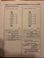
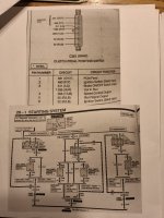
Still waiting to see if the auto EEC is going to be an issue. research was inconclusive for a 5 speed swap and auto comuter. Most of the truck posts suggest to "just get the computer and harness for a manual". But that isnt an option for vans. I have a manual f250 5.8 speed density computer and no harness, waiting for a friend to get the EEC pinout diagrams of that and my 93/94 E250 5.8 auto to see if I can use an extra auto harness to repin it for a manual EEC. The risk of running the auto EEC, from what little I could find, was odd idle and/or throttle response due to accounting for torque converter or something like that or if it goes into a 3k RPM limiter type of safe mode with no transmission feedback or something along those lines. At this point I've committed and if the computer side goes to crap I will at minimum run a TBI EFI kit, Top end kit, or less likely the MAF overlay conversion(running low on patience still a lot to do)...

Pictures with descriptions, steps, maybe some part numbers to follow.
 
Last edited:

cutnchopit

Member
The main task I've focused on for the manual swap has been the pedals. everything else should be somewhat standard or straight forward.

The 92-96 f series and bronco pedal assembly puts the clutch master cylinder to the right of the brake master/booster. I wanted to have as many accessible ford parts and limit "custom" parts.

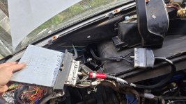
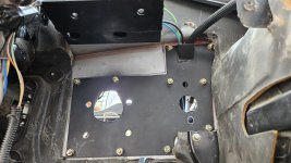
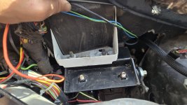
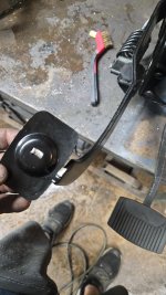
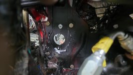
That puts the clutch master right where the computer goes through the firewall. First thought was to turn it horizontally, maybe above the clutch master, but it likely wouldnt fit. Then the idea of encapsulating the EEC and leaving it in the engine bay.. migh work, but heat was enough of a concern I kept looking for other options. Thinking surely there was an F series truck waterproofed for mud bogs I searched and found a "ford 007-00081 Rotunda EEC-IV monitor adapter" essentially two EEC extension cords so I can relocate it 4 feet away. The junction is the same size and in order to go through the firewall it needed a removable plate to fit through and then close up around the cord.

20250307_160846.jpg

Initially, I thought I would make the clutch master mounting part of the pedal assembly bolt on and move it to flush with the plate, but I held off and will see if it is rigid enough without it for simplicity. Another option would be to add a spacer on the right side of the pedal assembly and add an additional bolt to secure that part to the firewall and stiffen up that part of the pedal assembly, if the top bolts arent enough.
20250404_183617.jpg
20250403_162542.jpg

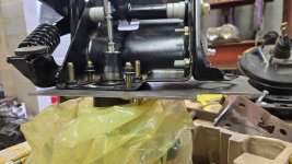
Here you can see how the truck master does not line up with the van master. You could choose to use the van pattern and modify the pedal assembly instead. I chose to use the top and right bolt thinking it would give me a little more wiggle room with the pedals and floor. but it also took away the wiggle room from cowl to booster/fill cap. I did not buy a truck booster to see if it would fit, it measured VERY close this way and may need to clearance the cowl if using a vacuum booster and aligned off the top bolt as shown. If you arent doing hydrboost, I would suggest mounting the master cylinder an inch or so lower for clearance under the cowl. with hydroboost it fits.

20250309_181358.jpg
Pedal F3TZ2455A
ford 007-00081 rotunda EEC-IV monitor adapter
Hydro Boost52-7079
 
Last edited:

cutnchopit

Member
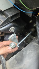
As part of the Hydroboost conversion, the pin on the pedal needed to be moved to be more in line with the booster, not necessarily part of the 5 speed swap, but it did have to do with the pedal assembly and was a point brought up in the hydro boost posts I read before doing this. I cut it off, drilled a new hole and welded it back on.
20250403_173602.jpg

The pedals I hammered more flat, and moved the foot pad to allow for better spacing, it was crowding the accelerator pedal at first, mainly because the brake foot pad was hanging off the pedal to the right.. maybe just flattening the pedal was enough or cut off the pad and weld it back on and not straighten the pedal. That seemed like more of a minor adjustment based on user preference. I ordered a new pedal assembly from a mishap trying to cut the splines into the arm, so I may try a different alignment when it arrives.
20250404_183529.jpg
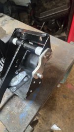
Another item to address when mounting the pedal assembly is the top mount. The van pedal assembly is taller and more shallow. So a spacer was needed to capture the top of the pedal assembly. I made this one out of 1x2 with some plate gussetted and extending out to hold the welded nuts for the pedals.

20250404_183553.jpg
 
Last edited:

cutnchopit

Member
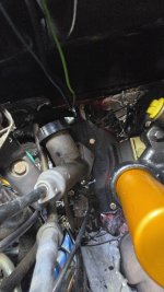
The engine bay.. so inconvenient. There may be another clutch master cylinder that isnt mounted at an angle to fit next to a vacuum booster, or that the hose goes down instead of out.. or even better would be an aftermarket master cyl. with remote resevoir.. because this crooked thing is under the cowl and needs a funnel to fill.. and also touches the AC line. I went with the factory style part to try keeping it all parts store capable. I unbolted one of the AC line tabs and bent the other one where it no longer contacts the master cyl. you can see why I talked myself into the hydro boost. 20250404_184341.jpg20250309_182035.jpg
 

cutnchopit

Member
On final install... I snapped the bolt off of the clutch pedal end.. where it should pull into/cut the splines like a wheel stud.
20250625_163432.jpg
So that was fun.. ordered another pedal assembly and beveled the edge of the hole on the arm to help it align and slide on the splines.
I got about 25% of the way there and snapped the stupid thing again.

My response was to kill it with fire. I welded the arm on the end and tried a wet rag/water to keep the bushings from completely melting. This gives me zero adjustibility for the clutch rod and of course it seemed to be off one spline or so and it kept the spring return from pushing the pedal back the lasthalf inch or so. I plan on finding a used pedal assembly to swap it out eventually so it already has the splines cut and it can be adjusted. Also the aftermarket clutch pedal bushing upgrade could allow for adjustment if I start having issues with it.
20250628_203504.jpg
The second brake pedal assembly had the pedal snap off from a crappy weld while shuffling around during setup. so thats another reason to go OEM used clutch pedal assembly aside from the splines already being cut. But I went ahead and welded it back on with a little better spacing left to right. Re used the brake pedal I had previously redrilled for the hydroboost.
20250628_203516.jpg

without the ability to hold the arm in place as well when welding or adjust it a spline or two I ended up notching the ECU firewall area to have the clutch master sit flush against the filler place and a little closer to help with that alignment. Ugly but fits a little better.20250629_164034.jpg
 

cutnchopit

Member
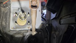
I originally cut the pedal assembly into two pieces to help with install and then left it out since the firewall was beefed up. I drilled through the two pieces to be able to bolt it back together instead of welding it if needed afterall. After installing the pedal assembly and pumping the brakes/clutch a few times I saw a small amount of flex in the pedal assembly and installed the clutch portion of the assembly to help stiffen it up a bit(looks the same but you can see the bolts on the right side pointing to the left. It takes FOREVER to bleed the hydroboost setup. online said to lift the front wheels off the ground and turn it left to right 5 times, pump the brakes 3 times.. and repeat 90 times or something like that.!!
20250629_173254.jpg
But IT MOVED!! a bunch of transmission codes and needs a tune up from sitting but it moved! 20250629_172907.jpg
 

Forum statistics

Threads
189,833
Messages
2,921,458
Members
232,931
Latest member
Northandfree
Top