Folks with LED strips on your awnings - how to you route cables inside vehicle?

Herbie

Rendezvous Conspirator
I've been inspired by all the folks with LED strips inside their awnings. I added some to my new ARB and it's mostly great, but I'm a bit unhappy with how I've routed the power/signal cable to the inside of the van. (I have to be careful when opening/closing passenger door and slider to be sure I don't snag the cable.) I've been hoping to see other's implementations and cable routing to get some better ideas.

So how to you route cables (power or signal) from a connection in the vehicle out to your awning? Permanent or something you re-connect on deployment? Photos, please!
 

mmaattppoo

Adventurer
I went the permanent route of using Amphenol military circular connectors for routing 12 Volt power from my aux battery inside my JKU Wrangler's through the hardtop to my roof top tent:

802ca6780644d601f9a6c45bca467f59.jpg


2fd42494da633cfb4c4f2024bb1e6e83.jpg


40083e0e061e5843dc6a28ad9798eba5.jpg


I installed a second through roof connection for a 75 Watt solar panel mounted on my roof rack (not pictured but similar to the images above) and a third through my license plate holder for a 150 Watt folding suitcase style solar panel. Pictures of the license plate installation are below:

ab5d999fe80bcc0834a2475bdb0112f5.jpg


99ed6bf2f1cff42bb384f8fe401aec89.jpg


Circular connectors come with a rubber gasket and install easily. After a couple of years use the first connector installed through my hardtop has never leaked. These or similar through hull deck fittings may suite your needs.

041b30dca8b42a94bcccf1f3c583ad39.jpg


I like the circular connectors since you can unplug the exterior power cable from them, screw on a dust cap, and store the power cable separately.

Sent from my SM-N920W8 using Tapatalk
 
Last edited:

mmaattppoo

Adventurer
Yup. I'm based in New Westminster and locally sourced these connectors from MRO Electronics on the west side of Boundary Rd south of 1st Ave. Here's a link to their website:

http://www.mroelectronics.com

It's best to go in to the store and see these connectors first hand. There are so many sizes, configurations, and bits and pieces that you'll best be served by talking to the staff at MRO to ensure you get the connector that best suites your needs and all the necessary parts.

I typically go with the two or three pin connectors; two pin preferred since DC applications don't need a third neutral...just +ve and -ve. The size of the connnectors are determined based on current carrying needs and physical space constraints.

Hope this helps.


Sent from my SM-N920W8 using Tapatalk
 
Last edited:

Yarjammer

Wellreadneck
I mounted an ARB socket holder with a Blue Sea 12V plug insert on my hood cowl so that I have some flexibility of what 12V accessory to connect. I sometimes attach an articulating spotlight (pictured below) when on the trail and the awning while in camp. It is also nice having a 12V outlet when hanging out somewhere and being able to charge a phone, inflate an air mattress, etc without having cords all over the place through an open door or window.

JKU 12V.jpg
 

bstory

Observer
We just use self-contained battery powered LEDs - the AA batteries usually last about as long as a trip, but we don't use them every night.
 

Accrete

Explorer
We went super simple. Picked up a 30ft string of LED lights from Amazon for under 10 bucks that can be run via 5v USB power supply (example link on amazon). String them up via gear ties between awning supports, plug a small USB battery pack, and walla... camp-trail bling to rival any shinny tin-can with plastic pink flamingos in the camp ; )

AWDcamplights.jpg


Thom
 

mmaattppoo

Adventurer
I too struggled with this issue the first time I used these connectors.

As far as I know the male and female pins are solder connection only. There may be a crimp connection variety but I haven't seen them.

The following is a general summary of what's worked for me. This is not a definitive guide to the process of soldering and making the connection between wire and connector but it should get you through it.

For best results I very carefully remove the pins using a pair of needle nose pliers. I've tried soldering with the pins in the rubber gland and it just makes a mess and you end up with cold solder joints.

You will need to push the male pins carefully by firmly gripping the rounded male end and pushing until each pin pops out. The female pins are removed by carefully inserting the tip of one side of the needle nose pliers into the female pins and pushing until each pin pops out.

Be careful when removing the pins as they are somewhat brittle and break easily.

Once you have each of the male/female pins out of their respective rubber glands you can prep for soldering and shrink tubing.

A couple of questions:

1) What size Amphenol connector did you end up purchasing? More importantly what's the approximate diameter of the end of the pins that receive the wire and solder? In my case the pins are approximately 2mm in diameter and required a bit of careful soldering to accept 12 ga wire...SOOW 12/2 in my case.

2) What size/type of wire are you attempting to run through your connector(s)? As mentioned above my experience has been with 12/2 SOOW cable...pretty much the maximum size of wire that you could conceivably solder to the pins and still fit through the rubber seal portion of the male end strain relief unless you sprung for a very large connector. Here's what SOOW 12/2 looks like:

217eb64c6e56aa3327cd8ce7b1c80fd6.jpg


Do a dry run assembly of the two halves of the connector to ensure that everything goes together properly. A consideration to bear in mind is the total diameter of the wire (including the insulation and making an allowance for shrink tubing) being terminated with the connector. The rubber seal that's part of the strain relief needs to fit over the wire and any solder joints. I've typically had to use a little silicone grease to make things fit as SOOW cable is a bit of a stretch for the rubber strain relief seal.

As for soldering and shrink tubing, you will need to do the following for each pin:

1) strip each wire to be connected ~1/4 to 1/3 of an inch.

2) tin each stripped length of wire.

3) tin each of the pins where the wire connects.

4) make the solder connection between wire and each pin.

5) cut a short length of adhesive lined shrink tube (appropriate diameter for the wire you're working with) and apply to the solder connection. This is an important step to avoid potential shorting and corrosion issues down the road.

6) test the continuity of each pin/conductor with a DMN to make sure the solder connection is good.

Assemble each half of the connector and carefully push the pins back into their respective rubber glands.

As shown in the photo in my original post (from inside looking up at the roof), the female side of the connector doesn't have any strain relief. To provide some strain relief between the wires/cable you will want to add a couple of layers of adhesive lined shrink tube that seat onto the base of the female end of the connector.

Hopefully the above summary hasn't glazed over too many details and provides you with what you need. There are a lot of steps but they're not too difficult...with a bit of practice.

Cheers!


Sent from my SM-N920W8 using Tapatalk
 
Last edited:

mmaattppoo

Adventurer
Thanks for the info! I just finished up my own wiring for this connector and am glad to read that we did most things similarly.

I stopped by Lordco and Home Depot in hopes of finding a connector, but no dice, no one has even seen these things before.

The 2-pin connector I have is labeled YEONHAB 16-11, and Y/MS3102E 16-11P 1422. I am not sure of the guage of wire that I ended up connecting. These are the original wires that came with my Renology 100W solar panel. I am guessing it is around 8-10. Definitely larger than what the connector's pins are intended for.

First off, I decided to retain the original connector on these cables in order to not cut the cables attached directly to the solar panel, and as such, I made the cut in the long batch of wire (that runs to the solar controller) about 20" below the original connector.

My first attempt was to solder the wire directly to the connector's pins. The tight spacing and my borderline zero soldering experience (haven't touched a soldering gun since high school electronics some ~11 years ago) resulted in a horrible mess. I spent a good 30 minutes with a rotary tool, trimming off everything I had soldered on to that one pin.

I then tried to remove the pins as you did - no dice, I could not get them off. I used needle nose pliers and tried pushing, pulling, wiggling, etc. I ended up doing everything with the pins still attached:

My second idea was to take a butt connector with an inner diameter just slightly larger than the half-round pins, strip off the insulation, and hammer it on to the pin. This worked well, and I then soldered the pieces together. This gave me a taller, tubular pin to work with. Unfortunately this butt connector's inner diameter was still smaller than my wire, so I added another, larger butt connector on top of it - that gave me the room I needed. I tin'ed the wire, inserted it into the larger butt connector (now part of the pin), crimped everything together and soldered. Then came two layers of shrink wrap, and the same process for the other pin. With both pins done, I used liquid tape to completely fill & insulate the area around the pins.

For the other half of the connector I had a third idea: solder on spade terminals. Same approach with insulation as in idea #2. This is the best of the options I used, as it makes it very easy to attach other wires in place of the ones I have now.

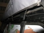
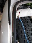
Here are a few (admittedly not the greatest) photos:

8CGZuoI.jpg


jznC1Vu.jpg


89ADtbz.jpg


xoH17CI.jpg
Glad things worked out. One thing you may want to consider on the end where you used zip ties is strain relief:

e689cb5543a06762b39e48e75c825dfe.jpg


This will take the strain of plugging/unplugging the cable off the connection between the pins and wire and transfer it uniformly to the cable improving the reliability of the connection.

Sent from my SM-N920W8 using Tapatalk
 

mmaattppoo

Adventurer
That would have definitely been a good idea, but at this point I think it's too late. My wires have large (original) connectors on the other end, so I can't feed them through that strain relief's opening. Don't want to re-solder everything. And I suspect the two of them would not fit in that opening in any case (it's an incredibly tight fit with the larger diameter of the currently open end. Will keep that in mind for any future use of these types of connectors, though!
Do you have an image of the finished product with your panels, wiring, and charge controller setup? I'm always interested in seeing other people's systems as a source for continuous improvement.

Sent from my SM-N920W8 using Tapatalk
 

Forum statistics

Threads
188,667
Messages
2,908,743
Members
230,892
Latest member
jesus m anderson
Top