I have a 77 K20 with the manual transmission. I recently converted it to hydroboost with a unit that I got from Vanco (
http://www.vancopbs.com/category_s/66.htm ) The bracket he made to mount it to the firewall required slotting the holes to match up to the studs and I also had to open up the hole in the firewall a bit to accommodate the nut that Larry showed above and mentioned it is tough to get to. I told him about these issues and he seemed surprised, so maybe I got the wrong bracket somehow. It was not that hard to make it work and a round file, or dremel tool with a mill bit would make short work of it. It is just worth mentioning, I thought. My brake pedal already had a hole from the factory above the pin that the master cylinder hooks to. Apparently the pin got installed in the upper hole for hydroboost and in the lower hole for vacuum boost. I ground off the riveted portion from the back side of the pin and knocked it out of the hole. I then installed it in the upper hole and back welded it to make it permanent. The Vanco unit comes with the linkage that connects from the booster to the pedal and everything else you will need. The only thing you need to do is move your existing pin to the upper hole and weld it in place as I mentioned. According to Vanco the pump needs to put out 1200-1500 psi. You can either modify your pump if it is in good shape or replace it with a new one. Here is a link on how to modify it:
http://westtexasoffroad.homestead.co...rsteering.html
They also sell them with the modification done already, but it is easy to do and cheaper to do it yourself. Larry mentioned that the higher pressure is not necessary, so I certainly would try my stock pump out with it all to see how it works before bothering with any changes. My pump needed replacement anyhow, so it all fit into the big picture.
I thought it may be helpful to list some reasons as to why I decided to convert it in the first place. First of all, my master cylinder was leaking, and the leak was partially going into the booster. Both components needed replacement anyhow, so the time was as good as any.
Secondly, I often use my truck to haul heavy loads of firewood, trailers, tractors etc that it really could use some extra help stopping reliably. Leaving extra following distance is a good idea, but when some twit in a honda jumps in the space you are leaving for safety and slams on brakes, you better be able to do something about it. As it was, I was relying way too heavily on the trailer brakes in those circumstances.
Finally, I have a lot of experience driving other trucks with hydroboost, own a 2001 suburban with it and have always liked the extra stopping power that it provided. The great brakes on the Suburban really pointed out the inadequate brakes on the pickup and I finally made the swap.
So why the Vanco unit? It certainly is more money to do it the way I did, instead of the route Larry took with the salvage parts. I am definitely a salvage parts type of guy, but the main issue was time for me. I really did not feel like I should spend the time to locate an acceptable unit, and install it hoping that it would not have any leaks or other issues that I would have to spend time sorting out later. I am very busy currently and felt that I really did not have time to tweak things and get the cobwebs out of used parts. I suppose either path is just fine, but for my current circumstances, I felt this was the best route for me.
Anyhow, so far as the swap goes I believe it is pretty straight forward. I will attempt to give an overview of the various tasks involved with the swap.
As I mentioned above, the pin for the linkage has to be in the upper hole in the brake pedal. The pin is inserted in the hole and the back side is riveted from the factory. My truck already had the upper hole from the factory, and I have another spare set of pedals from a 1973 model that has both holes as well. Even if it did not have the upper hole from the factory, the hole could be drilled if necessary. The booster linkage needs to be as straight as possible, so it would just be a matter of holding it up to the correct position after the booster was installed, marking and drilling the pedal. Then put the pin in the correct hole and weld it to keep it in place. In case someone is not familiar, the pedal swings on a special bolt that has to be removed. The bracket / housing can all remain under the dash. If I had it to do over again, I would have ordered a new set of bushings from LMC for my clutch and brake pedals, but I was lucky enough to piece together a decent set since I had an extra pedal assembly. The plastic bushings are cheap and available though, so there is no reason not to get a set on hand prior to working on it.
Here is a link:
http://www.lmctruck.com/icatalog/cc/full.aspx?Page=155
Part #10 in the drawing shows the plastic bushings for the clutch pedal. They are the same for clutch and brake pedals, so for an automatic you only need 2 instead of 4 to do clutch and brake pedals.
Removing the old booster is not worthy of discussion, and the new booster fit into place just fine. Hopefully Vanco has his bracket situation sorted out since I mentioned it to him. I did remove the bracket from the booster to make the hole slotting process easier, but would not have been necessary other wise. The nut that holds the bracket onto the booster must be able to penetrate the firewall because the bracket mounts flush against it. The hole in my firewall had to be enlarged slightly to provide this clearance.
Once the booster/MC was bolted in place the brake lines are hooked up. The master cylinder I got had the holes for the lines swapped as compared to the old one. I asked him about this and he said it was normal to have to swap front/rear positions on the lines sometimes. The threads were correct, so no issues there. Then the routing for the hydraulic lines must be determined and cut to length. There is nothing really to mention about this except that you may want to consider plumbing in a cooler. Most vehicles that I have worked on that came with hydroboost from the factory come with a cooler, so I thought it best to install one. Vanco said this is strictly up to the individual, but since I was plumbing the lines I decided to go ahead and do it. After running it long enough to do the bleeding process, I was surprised at how quickly it had warmed up even without driving it. I used a small transmission cooler because I found a good price on it. Link:
http://www.amazon.com/Hayden-Automotive-676-Rapid-Cool-Transmission/dp/B000C39CL8 I think most any cooler you come up with would be fine, so long as you have the space for it. It is good to take plenty of time to route and secure the hoses properly to avoid any chance of hoses vibrating against something that could create a hole in it. I over engineered mine and used bulkhead fittings to penetrate my radiator support because I just was not satisfied with the options for a route where nothing could hit them. I also used hard lines for the most part, but this was not necessary either. I tend to make things more involved than they really have to be sometimes, but I really hate having to go back and do something again because I didnt do it right the first time.
I was not aware of the bleeding technique that Larry mentioned above, and I did have a few times at first where I apparently had some air remaining in the system after bleeding it. It was not a big problem, but there were a few corners I had to make with no power steering. It worked it's self out and is fine now though.
All in all, I feel that it was a pretty simple swap and was pretty much bolt on. The hose routing for the cooler took a bit of time, but I really wanted it to be secure and out of the way. I am really happy with the results. So far, I have hauled one load of firewood with it since making the swap. It wasn't a terribly heavy load, but the extra braking power was great. I really should have done it years ago!
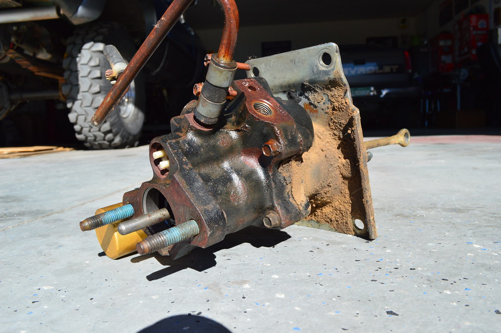
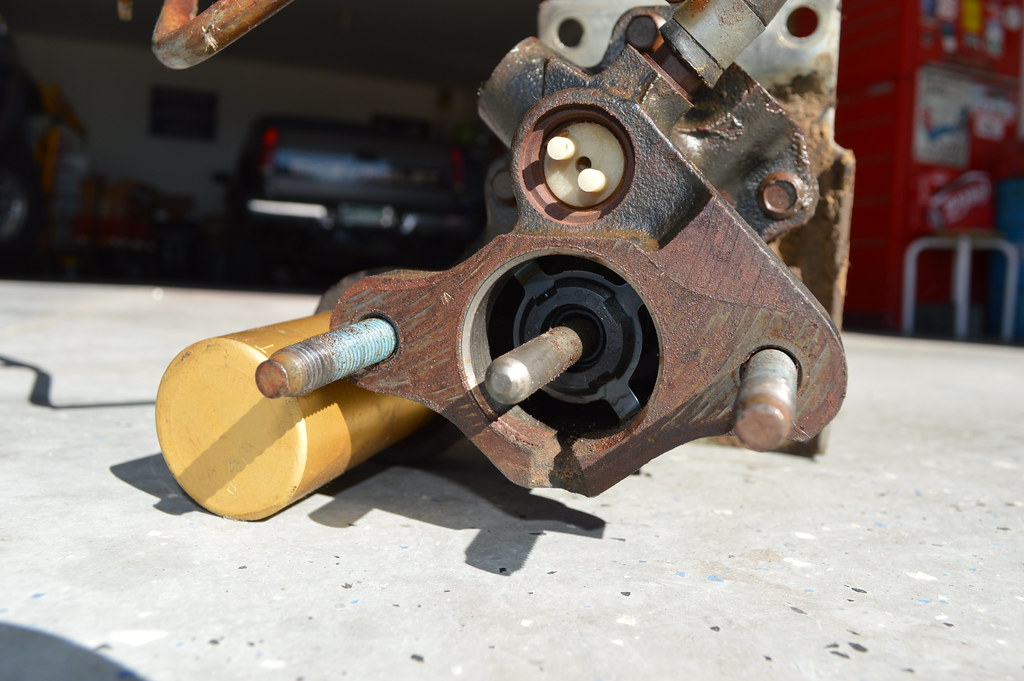
Here are a few pics of it all:


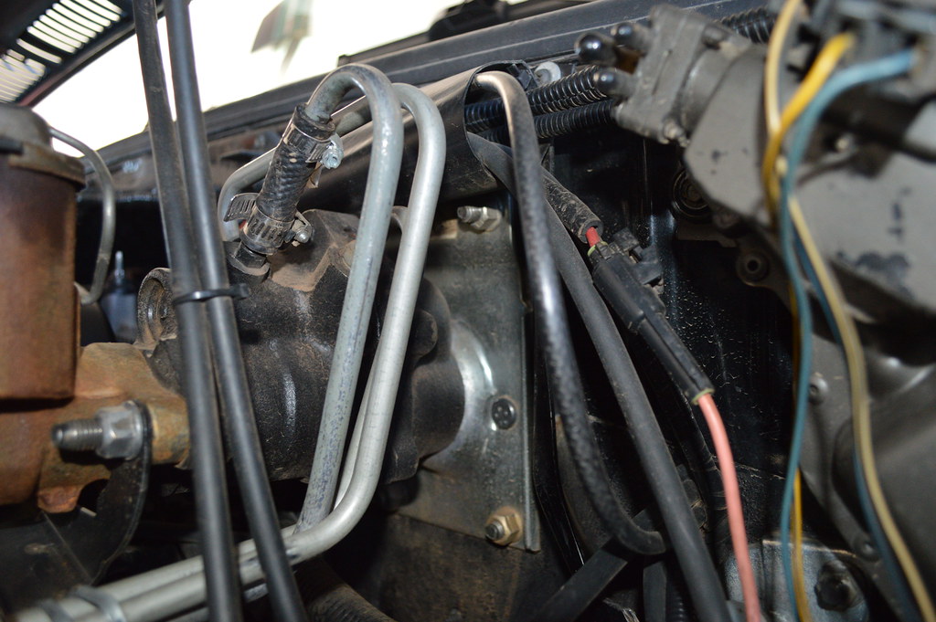
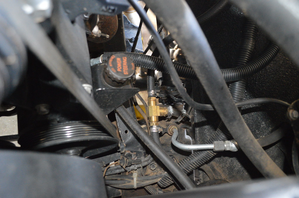
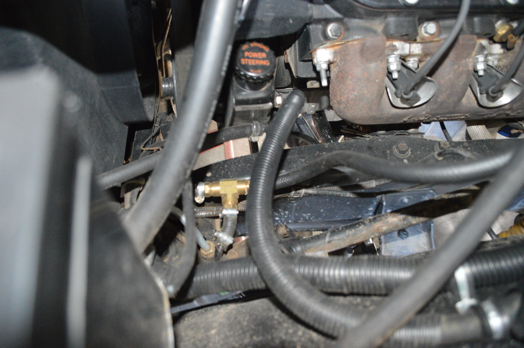
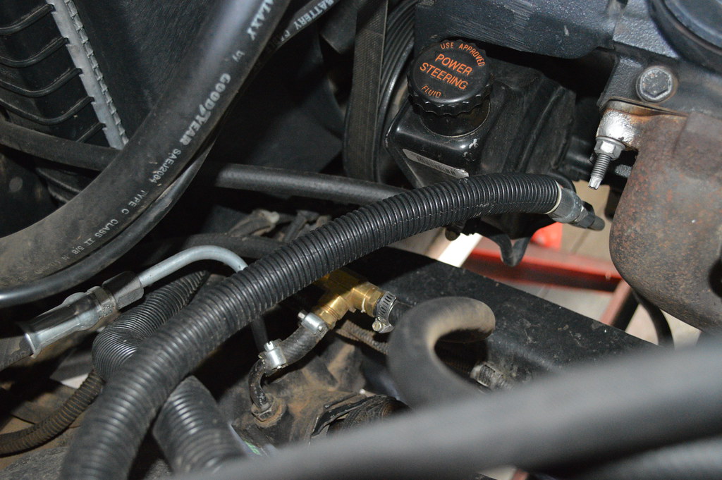
The picture below shows the supply line going into the steering box and the return line leaving it to go to the cooler. The line coming from the cooler can be seen going over the frame rail before it T's into the return line from the booster as it heads to the pump. I put some rubber hose on it as a chafe guard where it is close to the brake lines.


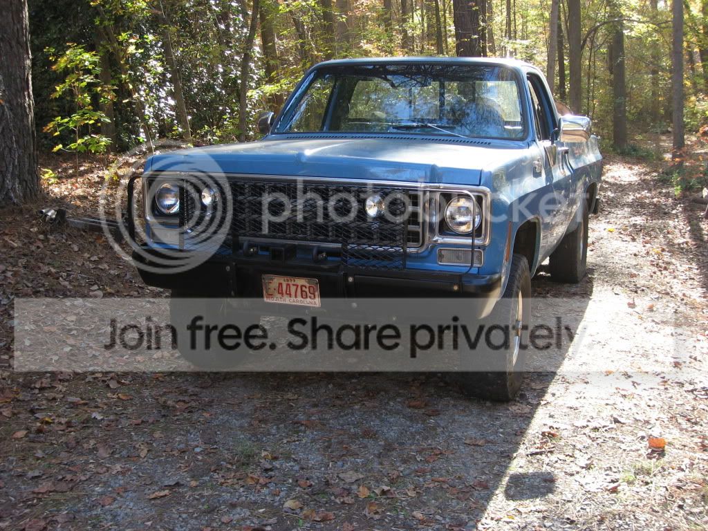
Here is a photo of the truck and my best helper!

")