Looks like a fun project. Based on the BlueSea 12v current chart it looks like your 2/0 and 6 awg wires are protected by reasonable sized fuses that are located near the power source or where wire size is reduced.
A couple of suggestions:
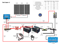
- I'd recommend adding add another switch between the solar charge controller and the positive bus bar. That would allow you to shut off +12v from solar when you are working on the panels, and you could shut off all power by turning off that switch and the switch for the batteries. Also, since the charge controller is a current source you might want to put a fuse close to the controller to protect the wire going to the terminal block. Blue Sea likely has recommendations for how to fuse this device.
- The 2/0 wire for the chassis ground is probably overkill and you could save some money and weight by going with a smaller gauge wire. With the current design the only power using the chassis as a return path would be through the 60A feed to the fuse block.
- What is the max draw of the inverter, is a 60A fuse large enough?
- The fuse size chart in the upper right includes ~5 different fuse sizes. Generally the idea is the run wire that is large enough to handle the current draw of the load and then to size the fuse to protect the wire. To simply things you might want to select 2 wire sizes (one large, one small) and 2 sizes of associated fuses. That way you could buy them in bulk, and you would reduce the number of spare fuses you need to carry. For example, 14 or 12 AWG wire protected by 10 or 15A fuses for most of the circuits, and something larger for the dual USB plug (can it really draw 25A?).