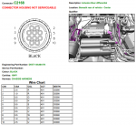
The ConOps makes things pretty clear. The next big part is obviously the wiring. Unfortunately, if you don't have the stock rear locker, you also don't have the wiring for the stock rear locker. So this is a large part of the project - finding/making all the harnessing.
You can find the wire diagrams in some of the pirated service manuals. I ended up getting a single day subscription to Topix, and wow is there a lot more in there. All wiring for the LR4 is extensively documented and its so nice to see and have access to. You can not only get the diagrams which have the wire size, length, and to/from, but you can also get the connector information including wiring pinouts, positions, part numbers, etc etc, which is a life saver.
LR4s aren't super common (obviously), so instead of trying to hack out the required harnessing from a totaled vehicle, I decided I'll try to make my own harness.
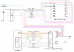
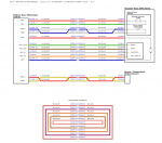
The wire diagram for the locker is broken out into three basic diagrams: the rear diff control module to rear diff actuator and temp sensor, power to the rear diff control module, and CAN connection to the rear diff control module.


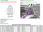
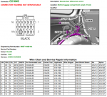
When I got the TOPIX subscription, I was also able to download all the datasheets for each connector listed in the diagram. The data sheets provided the pinouts as I had mentioned along with part numbers (if it was 'serviceable'), and it also provided wire repair information. For most of the connectors, you can get pre-terminated contacts that you can add into the connectors. This allows you to essentially add wiring exactly as though it was factory. The catch is some of them are stupid expensive, we're talking $100 for a pack of 10 contacts. So, as much as I like to maintain things as factory as possible, there are a few things I am not going to do:
- I'm not going to try to pin into the factory fuse box. A: the pin costs are dumb. B: its behind the glove box, where the diff control module is on the driver side rear quarter panel, so wiring to that seems like a nightmare.
- Since i'm not pinning into the fuse box, I'm also not going to pin into the engine junction box.
- I'm going to bypass the connector between the diff control module and the diff itself. Again, the cost of those pins is crazy.
To get around these issues, I bought a new power distribution box to put in the engine bay. Just a simple bussmann style box that accepts relays and fuses. It will be more then enough to support the power needs of this project, and provide some slots for future projects. I'll have to figure out how to bypass the connector between the diff and the diff control module once I'm in there. I'm not too concerned with that part.
That just leaves the connectors to the rear diff and the connectors to the ECU.
The ECU connectors were the easy ones. I was able to get some part numbers from Truckin's post and found them commercially available. The connectors for the diff however are much harder. I couldn't get any useful part numbers from the actuator connector, which is kinda the most important, and ran into dead ends when trying to source just the connector. I decided I'm going to solder wire directly to the diff pins and add in a new connector that I can source. I deal with a lot of D38999 connectors in my life, so I opted for some of those, which will require a custom bracket to mount them on, which shouldn't be a big deal. I'll also get that figured out once the new diff arrives. I'll also need a connection to the power distribution panel to keep things modular and easy, but this one just sits in the engine bay so something less 'stout' then a D38999 is fine. I found some great looking AT family Amphenol connectors to use. We'll get back to connectors later though.
With all these changes I drew up a new wire diagram. I cannot stress this enough - DRAW WHAT YOU ARE GOING TO DO. You're life will be much easier when your doing it. Obviously if you're doing this yourself, pick whatever connectors will work for you. D38999s are expensive.
