SnoViking
Adventurer
Hey Everyone, So I'm in the process of building up my new truck and I'm getting to the point where I'm starting to add accessories like driving lights, back up lights, USB plugs, fridge, etc. I started thinking about the wiring and how and where to do things. I then remembered how much I hated running switches and wires back into the cab (through the firewall). I've had water ingress (aka soggy floor mats) caused by improper wire management and I've never been happy with aftermarket switch fitment (although I will say they've improved vastly recently). I like my vehicles to look as stock and clean as possible. Whilst sitting in traffic this morning it occurred to me that I have three switches already neatly installed, wired up, powered and lit, that I don't use. These would be the three garage door opener buttons up above the rear view mirror. It got me thinking.......
So here's my plan (cue the A-Team music):

These switches, when pushed, send off a specific code/string at 315mhz (+/-). This is what the garage door opener receives and then tells your door to magically and ceremoniously raise.
So my plan is to build a control box using an Arduino board, a radio frequency receiver, and some relays to toggle the accessory relays for such things as my driving lights, back up lights, and USB outlets.
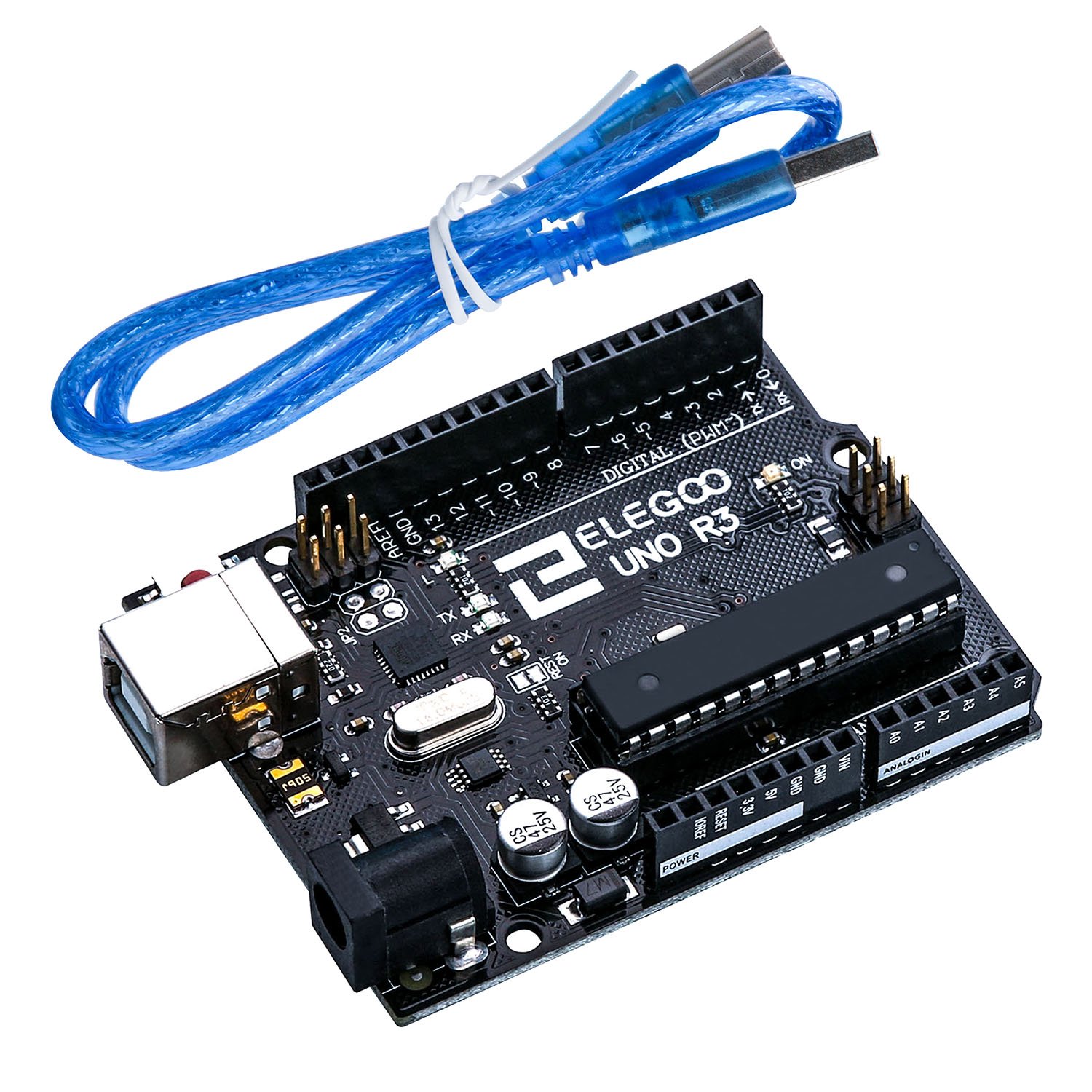
I plan on using the Arduino Uno board since it is already 12VDC powered. This little guy will give me all the functions needed and is nice and small.
I'll wire up a radio frequency receiver which is designed to receive at 315Mhz (the garage door opener frequency)

I'll then connect the Adruino board to a set of "stepper" relays which will take me from 5V 12-20mA current up to 12VDC 10A.
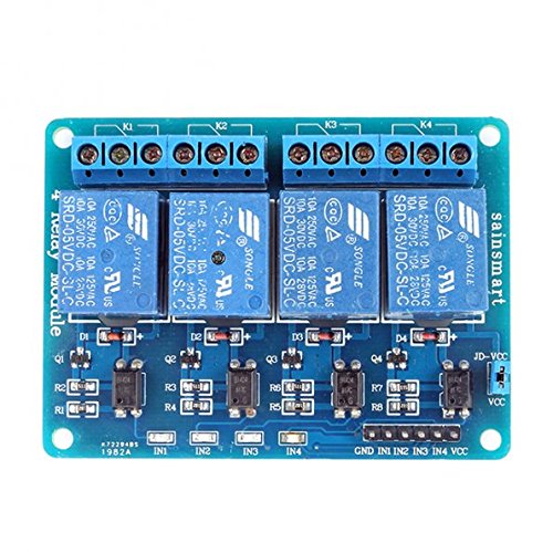
I'll use those relays (the blue ones) to run a standard 12VDC 40A (max) automotive relays. These will run the accessories.

Then I'll have to figure out the code writing stuff and "Ifs" and "thens" and "If elses".....
I'll update as I go.
If anyone has any coding/Arduino experience and wants to help please chime in. I feel like almost everyone has these button in their car and it would make running accessories a bit easier.
So here's my plan (cue the A-Team music):
These switches, when pushed, send off a specific code/string at 315mhz (+/-). This is what the garage door opener receives and then tells your door to magically and ceremoniously raise.
So my plan is to build a control box using an Arduino board, a radio frequency receiver, and some relays to toggle the accessory relays for such things as my driving lights, back up lights, and USB outlets.
I plan on using the Arduino Uno board since it is already 12VDC powered. This little guy will give me all the functions needed and is nice and small.
I'll wire up a radio frequency receiver which is designed to receive at 315Mhz (the garage door opener frequency)
I'll then connect the Adruino board to a set of "stepper" relays which will take me from 5V 12-20mA current up to 12VDC 10A.
I'll use those relays (the blue ones) to run a standard 12VDC 40A (max) automotive relays. These will run the accessories.
Then I'll have to figure out the code writing stuff and "Ifs" and "thens" and "If elses".....
I'll update as I go.
If anyone has any coding/Arduino experience and wants to help please chime in. I feel like almost everyone has these button in their car and it would make running accessories a bit easier.


