Ambolorian
Member
The following post may cause heart palpitations and/or nightmares. Read on at your own risk.

Here is my 2002 E350 Super Duty with Leader Ambulance package.
This rig comes with 2 starter batteries and 2 "spare" batteries that I will be replacing with a 300ah bank of Renogy AGMs.
My current project is to create two separate battery banks that are independently charged by the dual alternators up front.
I was able to get a bunch of schematics from Leader (no easy feat!) and some pics from another user on the forum that unfortunately is no longer active.
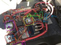
Here is what I have under the driver's side seat:
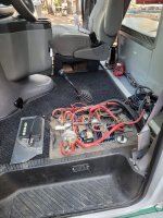
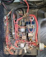
Here is breakdown of what each component does:
A: This solenoid is controlled by the Module On/Off switch above the driver.
B: This is the Manual ON/OFF switch mounted on the side of the front seat
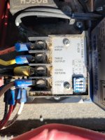
C: This is a timer that shuts off rear power 5 minutes after the ignition key is removed.
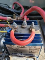
D: This is a Battery Isolator that takes power from the positive post (which is connected to the alternators and starter batteries) and sends it to the "spare" bank.
E. This solenoid is for Emergency Start and combines all batteries to start the diesel in very cold weather.

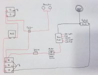
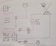
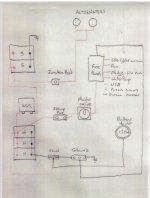
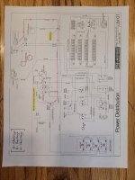
Here is the power schematic that Leader sent me:
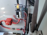
A closer look at D (Battery Isolator)
A closer look at the TImer:
Wiring at this level is a little daunting to me.. I'm hoping someone gifted with an electrical engineering background can chime in and answer some of my questions.
Here is my plan:
1. I'd like to remove C (Timer) and D (Isolator) and effectively have an independent "house" bank of batteries that runs the camper conversion led lights and sockets in the back.
2. I want to replace the current isolator with a Blue Seas ACR 7620 but I'm not clear on how to wire it into the system.
3. How can I bypass the timer?
Has anyone else worked on a rig like this before or have some suggestions for me?
Thanks!
Here is my 2002 E350 Super Duty with Leader Ambulance package.
This rig comes with 2 starter batteries and 2 "spare" batteries that I will be replacing with a 300ah bank of Renogy AGMs.
My current project is to create two separate battery banks that are independently charged by the dual alternators up front.
I was able to get a bunch of schematics from Leader (no easy feat!) and some pics from another user on the forum that unfortunately is no longer active.
Here is what I have under the driver's side seat:


Here is breakdown of what each component does:
A: This solenoid is controlled by the Module On/Off switch above the driver.
B: This is the Manual ON/OFF switch mounted on the side of the front seat
C: This is a timer that shuts off rear power 5 minutes after the ignition key is removed.
D: This is a Battery Isolator that takes power from the positive post (which is connected to the alternators and starter batteries) and sends it to the "spare" bank.
E. This solenoid is for Emergency Start and combines all batteries to start the diesel in very cold weather.

Here is the power schematic that Leader sent me:

A closer look at D (Battery Isolator)

A closer look at the TImer:

Wiring at this level is a little daunting to me.. I'm hoping someone gifted with an electrical engineering background can chime in and answer some of my questions.
Here is my plan:
1. I'd like to remove C (Timer) and D (Isolator) and effectively have an independent "house" bank of batteries that runs the camper conversion led lights and sockets in the back.
2. I want to replace the current isolator with a Blue Seas ACR 7620 but I'm not clear on how to wire it into the system.
3. How can I bypass the timer?
Has anyone else worked on a rig like this before or have some suggestions for me?
Thanks!

