EyeInTheSky's Gen 3 Budget Build Thread

EyeInTheSky

Adventurer
A quick update

Stopped by the machine shop yesterday to drop off the tensioner and thermostat. I'm pleased with the progress so far. The heads are nearly done; the passenger side head's camshaft had some corrosion on one of the lobes so they are sending it out to see if it can be reground or if it needs to be replaced. Doesn't hurt my original quote of $2,000, so that's good.

They haven't gotten to the block yet, but the shop manager estimates that it will be done mid week.

I've decided to have them do the reinstall. There are too many things that can go wrong with me doing it, so I'm going to bite the bullet and have the rig towed to the shop. Now to sell the hoist and stand and recoup some of my money. I'm at nearly $1,000 before even paying the machine shop between the tools, parts, and initial shop bill. There goes my mod budget...

I got my injectors back in the mail yesterday from the cleaning/rebuilding service. Results below:

Test Pressure: 45psi

Injector 1: 40psi > 42psi = 105%
Injector 2: 40psi > 41.5psi = 103.75%
Injector 3: 40psi > 42psi = 105%
Injector 4: 41psi > 42psi = 102.44%
Injector 5: 41psi > 41.5psi = 101.22%
Injector 6: 41psi > 42psi = 102.44%

Average gain: 103.31%

I found it interesting that they measured PSI instead of flow rate, but whatever. Does anyone know the original flow rate (cc/min)?

Not terrible for $10/injector. They replaced the filters and O-rings as well. I sent them the other three I snagged at a Pick N Pull and had them choose the best six. They ditched one of the six from the engine for one of the junkyard injectors. That being said, anyone need some injectors? PM me if you want to buy one or more, otherwise they're going on Ebay and you'll miss out on the ExPo discount. I'd suggest this same service on them (search FleaBay for ultrasonic injector, the one I used as out of AZ).

Wiring is my project for tomorrow; I'm thinking of setting up my in-cab toggles to switch ground rather than hot, just to simplify wiring (all are going to relays, no high-amp loads through my switch bank). When researching this, I never saw a logical reason for not wiring this way, other than the fact that the accessory will always have a hot line to it, causing a shock hazard (though not really on a 12v automotive system, that's more of a concern for 110 AC). Some voodoo about switches lasting longer (how? It's the same load), and to "stick with convention."

Thoughts?

Also expecting my MonstaLiner color samples soon... That's one mod I plan to leave room for in my budget. I'm tired of the black with desert pinstriping.
 

Sabre

Overlanding Nurse
Electrically speaking, switching DC ground isn't a problem and won't have any effect on the switches or lamps. As you note, the device will be hot to 12 volts at all times. While not a shock hazard, it does present an opportunity for a short circuit in an unswitched hot line. If a lamp housing develops an internal fault, for example, it could possibly result in a short circuit even with the switch open because battery ground and the chassis/body are tied together. A fire or fried wire is the worst case result, though a sneaky voltage drain is perhaps more likely. In any case, a properly-sized fuse on the positive wire should be placed as close to the power source as possible, and the circuit will behave exactly as if it were switched on the hot lead.
 

EyeInTheSky

Adventurer
Electrically speaking, switching DC ground isn't a problem and won't have any effect on the switches or lamps. As you note, the device will be hot to 12 volts at all times. While not a shock hazard, it does present an opportunity for a short circuit in an unswitched hot line. If a lamp housing develops an internal fault, for example, it could possibly result in a short circuit even with the switch open because battery ground and the chassis/body are tied together. A fire or fried wire is the worst case result, though a sneaky voltage drain is perhaps more likely. In any case, a properly-sized fuse on the positive wire should be placed as close to the power source as possible, and the circuit will behave exactly as if it were switched on the hot lead.

That's what I was thinking. My planned setup:

Accessory power side:
(0ga wire) Battery positive terminal > 80a circuit breaker > bus bar > (12ga wire) fuse in relay box > positive terminal on relay;
(12ga wire) Negative/ground terminal on relay > ground/bus bar (possibly using stock ground on passenger side).

Trigger side:
(20ga wire) first bus bar > positive trigger relay terminal ;
(20ga wire) negative/ground trigger terminal on relay > LED indicator in cab > switch > bus bar (dual grounds in steel below center console)

Does that make sense?
 

EyeInTheSky

Adventurer
Progress. I decided to work on the accessory wiring while I have the engine out. So much easier to be able to stand on the cross-member than contorting around the engine and heads.

I am going to start building a switch bank with six toggles that I'm going to mount on the front side of the center console armrest. I prefer toggle switches to rockers, I don't want to put toggle switches in where the factory rockers are (would look terrible), and the OEM-style custom rockers are way too expensive for my "Budget Build." The only issue is that I will have to remember which switch it which, since I won't be looking directly at it.

Right now I'm pulling power from the open spot on the fusible link, but will later move the main power line to my second battery once it's installed.

The fusible link has a 120A fuse, which leads to an 80A circuit breaker.

20170306_082053-2124x1195.jpg

The wire then cuts across the back of the engine compartment to a Blue Sea Systems bus bar. From there it splits out to accessory positive and trigger positive.

20170306_082058-2124x1195.jpg20170306_082119-2124x1195.jpg

As mentioned before, I'm going to be switching ground on the relay trigger circuit. To this end I ran a bundle of 20ga wire into the cab, routed it through the center console and up into the armrest.

20170306_082124-2124x1195.jpg

This is the ground bar that will go underneath the center console armrest and will be the switch/trigger ground.

20170306_082046-1195x2124.jpg

I need to get the air box mounting plate back from the machine shop (they're hot-tanking it, along with everything else) so I can reinstall the air box, which will dictate the exact relay box location (passenger side firewall, in between the air box and side).

I'm using quick disconnects heavily so I can easily change wire connections or disconnect accessories I'm having trouble with.

One thing I read about wiring accessories like this is that if it looks terrible, it probably is terrible. I'm taking extra care to keep everything bundled up tight and consistent. The only issue is that my wiring colors aren't consistent throughout, so I'm planning to label pretty heavily. I'm trying to keep all wires doing the same thing in the same section the same color (all wires from relay trigger ground to switch are blue, all wires from switch to ground are brown, etc.). It was just too darn expensive to buy wire by specific color/gauge than it was to get a multipack.

Also, I've been using this chart for wire amp carrying capacity. I'm trying to stay conservative with this however, and try to go up one gauge if possible.

More to come later.
 

EyeInTheSky

Adventurer
Got the relay box mounted and tested all relays. Engine is about a week away from completion.
e80c555bbf5b9be4196a3bb3babf2d95.jpg

b8f577c08e6ad21717e6cbc6d4df977c.jpg
 
Last edited:

EyeInTheSky

Adventurer
Baby steps.

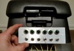
Switch plate is fabricated, LED indicators installed. Just need to crimp the other connectors on and mount the plate to the console.

20170313_205240.jpg2017031395212104.jpgswitch plate.jpg
 

EyeInTheSky

Adventurer
Looks great! What are you going to control with the toggles?

Thanks. I'm trying to future-proof right now, so I'm going to have some that are unused at first.

Front lights
Rear lights
CB Radio
AC Inverter
Battery-linking solenoid (Once second battery is installed)
Oil slick generator? :-D

Just hit an interesting wall however. I took the console out and connected everything but no luck. Each of the switches is connected to a relay, and I'm switching ground.

Battery > fusible link > circuit breaker > bus bar > relay trigger +

Relay trigger - > LED+ > LED- > Switch > ground bus bar

Here's the thing, I'm getting voltage across the relay trigger terminals, but only 1.75v (not enough to trigger relays). I'm getting 10.3v at the switch panel (switch to LED), and 12.5 out of the battery itself. The LEDs all illuminate when the switch is thrown. When I bypass the LEDs the relays work fine. Are my LED indicators causing that much of a voltage drop? Trigger circuit is minimum 20ga all the way around. Good continuity between negative bus bar in console and a different ground.

Going to play with it a bit and see if I can figure this out. I don't want to switch positive so I can avoid another bundle of six wires that have to penetrate the firewall, but I will if I have to.
 
Last edited:

OuterLimits

I control the horizontal and the vertical
Are my LED indicators causing that much of a voltage drop?

Grab your VOM. Test from the battery side of the LED to ground. Then test from the other side of the LED to ground. Subtract the two and you have your voltage drop.

Can you run the LED in parallel to the circuit instead of series? It should still light up, but will not create a voltage drop to the primary circuit.
 
Last edited:

KyleT

Explorer
Are the led lights rated for 12v? Also they are polarity sensitive. But since they turn on i assume they are 12 and correctly wired.

Its possible to have them in series drop the voltage. I would wire them in parallel for safety. If the bulb pops your switch is useless in parallel.


Sent from my iPhone using Tapatalk
 

EyeInTheSky

Adventurer
Grab your VOM. Test from the battery side of the LED to ground. Then test from the other side of the LED to ground. Subtract the two and you have your voltage drop.

Can you run the LED in parallel to the circuit instead of series? It should still light up, but will not create a voltage drop to the primary circuit.
TR

The weird part of that was that I was getting the 10.3v mentioned earlier at the LED, but only 1.75v back at the terminal. Instead of true parallel, I created another circuit. See below.


Are the led lights rated for 12v? Also they are polarity sensitive. But since they turn on i assume they are 12 and correctly wired.

Its possible to have them in series drop the voltage. I would wire them in parallel for safety. If the bulb pops your switch is useless in parallel.


Sent from my iPhone using Tapatalk


I think it was the LED's resistor screwing with the system since I had them in series. I decided to run a constant 12v positive in, soldered it to the positive terminals of the LEDs, and rewired my switches to add a second negative connection (one for LED - and one for relay trigger -). I then used a quick connect to bridge the other set of terminals and connect to ground so the LEDs and relays run ground along the same wires. I am using DPDT switches (they were the cheapest when I was looking around) so I had some flexibility.

If someone were to ask me today how good I am at automotive wiring, my answer would be, "Better than I was yesterday." Constant learning experiences throughout this project. I still closely identify with what another user said in their build thread: "How good of a mechanic am I? Well, I'm a good rough carpenter."

Based on what you see here, how likely is it that my rig will catch on fire? :-D The red blobs are heat shrink to cover the + terminals on the LEDs. I also put some heat shrink down on the relay trigger - terminals (blue wires), but couldn't fit them over the connectors on the LED - terminals (yellow). Going to use liquid electrical tape to protect them in case something tries to work loose while driving.

My new crimpers are on the way, so these nasty looking squish jobs on the terminals will be fixed early next week.

20170315_204622-1148x645.jpg
 
Last edited:

EyeInTheSky

Adventurer
Crimpers arrived so all connections are secure finally. Also picked up some marine grade shrink tubing for the more vulnerable connections. Engine is still in progress, hopefully done this coming week. Here's one of the heads looking all shiny and pretty.
195768fdea7fefc0acd9b9fa445eca48.jpg


I decided to add a couple charging ports for the rear so we can use them when I get the sleeping platform built, as well as when we have passengers in the rear. USB charger is on the way, and will be installed on the opposite side.
9cb280962b1db38b4bef829eda236d2b.jpg

b6638c08b2ddeeb0a0df4000adf07243.jpg


Couldn't find my larger bits, so I dug out one of my grandfather's old adjustable bits. This thing is great. I have another that goes up to 4in.

09a66056173013644b46fef7ac11961a.jpg
 

Forum statistics

Threads
188,190
Messages
2,903,611
Members
229,665
Latest member
SANelson
Top