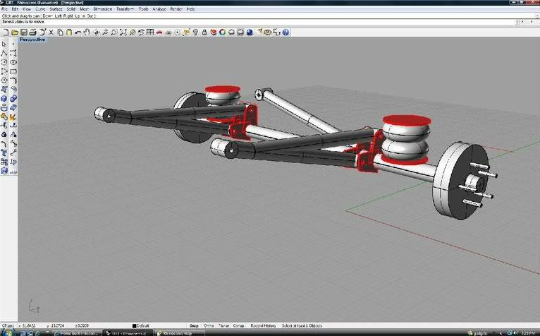
ive posted to several of the OP's threads, but here it is again. I use the "truck" or nascar style trailing arm setup. I have about 1800 miles of on and offroad pulling now on my trailer, and she pulls and handles like a dream. I would change absolutely nothing about the suspension at this point, which is NOT what I expected. I figured I would have to tweak a few things, but the very simple design works great on and off road.
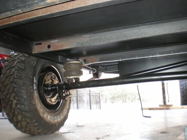
I set my loaded ride height, and the PSI is usually at 45-50. It rides awesome like this, with regular oem style new chevy truck front shocks (they were short enough for my application).
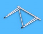
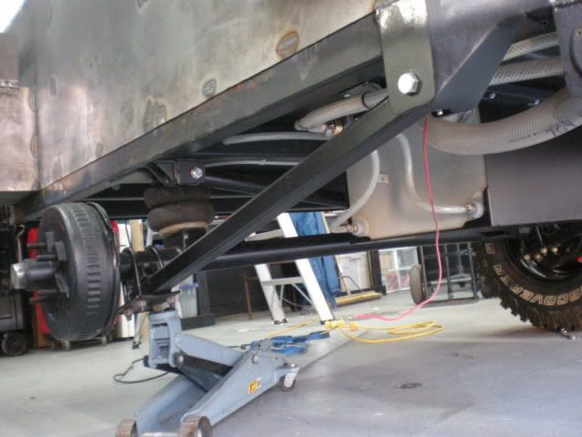
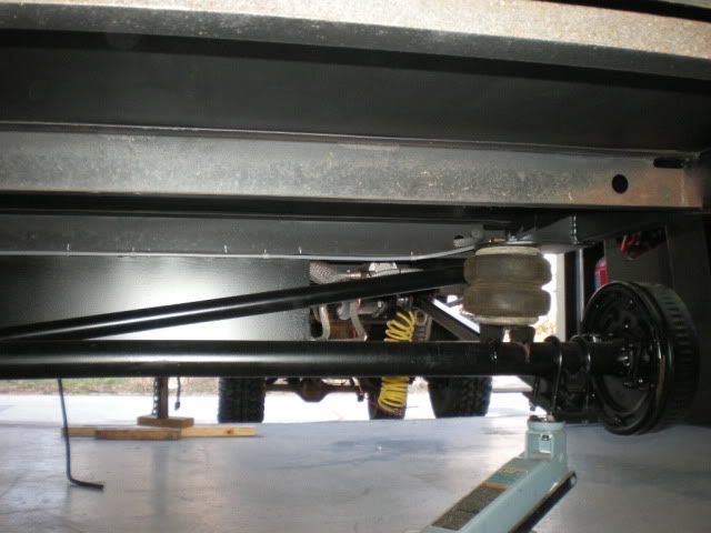
The shocks are not in these pics, but you gte the gist of it. Aside from the cool and/or bling factor, there is no need (imho) for any more than a two link with a panhard. There is zero need for an upper AND lower link with the way the truck style trailing arm works. No expensive Johnny Joints, and extra tubing.
There is plenty of 'give' in the u-bolt/spring pad set up on the trailing arm to eliminate binding even though the COUPLER takes probably 95% of the twisting motion.
I used .250 wall 1.5 square DOM for the trailing arms, and 1.5 inch .180 for the panhard. Ballistic fab grease-able poly bushing on the trailing arm frame ends, and the same on the panhard ends.
Again, the shocks are not shown in these pics.
Good luck with whatever you decide, you have certainly had a lot options thrown out there to choose from.
")