Double check my plan?

eatSleepWoof

Do it for the 'gram
I'm expanding my trailer's solar capabilities and am wanting to improve/clean up the custom electrical a bit.

My current setup lacks the buss bars and everything runs through a single, 60a circuit breaker. This has been working so far due to limited charging (at any one time), but I figure I should account for the possibility of all three charging inputs being active at once.

Does this look correct to everyone? Anything I'm missing?

It'll be 2awg wiring everywhere, except for the positive running from the shunt to the aux (non-battery) side of the 200a breaker.

CGvb2UQ.png
 

rubonik

New member
This isn't really complete enough for good quality feedback on the design.

It looks like the diagram only shows the outputs from your different battery chargers. For example, the DCDC charger should have a breaker or fuse as close to the vehicle battery as possible on the input side, and another between the charger and the house battery bank on the output side.

I don't understand the connection between the shunt and the 200A circuit breaker.

You can tie all the negative legs of the chargers together with a buss bar after the shunt.

If you have picked out the different chargers, use their manufacturer's recc's for sizing the breakers. Knowing what they are would help others give you feedback on the design.

Are you planning on using the circuit breaker as a kill switch for the positive leg at the battery?

Where are all the loads tied in? How many watts of solar will you have and how will the panels be wired upstream of the solar charge controller. Do you have an inverter?

You don't necessarily need 2AWG wiring and the chargers may not accept anything that large. I have a Victron MPPT 150/60 that can take up to 2AWG, but I also have a Victron MPPT 100/30 that only accepts up to 6AWG.
 

eatSleepWoof

Do it for the 'gram
@rubonik - Thanks for the reply.

I'm not concerned about anything upstream of the chargers. That's all setup properly, and you'll have to take my word for it :).

More just wanting to ensure I'm on the right track for everything on the output side of the three chargers. Using 2awg because I have it on hand, not out of strict necessity.

The (Renogy) shunt requires a ~18awg wire to the positive of the battery. In my current setup that runs to the single, common circuit breaker, and I'm planning to keep that same layout.

I've sized all breakers at 125% capacity of the maximum input that the charger is rated for. And yes, I'm wanting to use the 200a breaker as a kill switch, when necessary.

The loads are technically through the "converter" circuit. No inverter at this point, although I may add one in the future; if I do, I'll run new wiring for it to the battery location.
 

llamalander

Well-known member
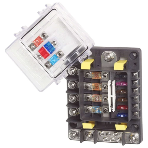
You might consider the Blue Sea 7748 fuse panel; rated for 200-amps (which should work with your battery) and is essentially a fused buss-bar. The larger MIDI fuses work well for larger inputs like the solar and DC-DC (not sure what the convertor on your diagram is, AC input?), the smaller (30-amp max) blade fuses work well for loads. I'd put the Renology shunt on a 7.5 or 10-amp blade fuse to protect the skinny wire.
The whole thing can be protected with your 200a breaker/kill-switch and all of the neutrals can gather on the 7748 before going to the shunt on a single wire.

While it may be less expensive to assemble something similar, nothing will be as compact and easy to access, I think the cost is well worth it.
s-l500.webp


I've used this for a number of years and enjoyed how compact and easy to configure it is. I have Solar, DC-DC and shore power (at 12v.) coming in, a sub-panel in the truck bed uses the last MIDI fuse. Blade fuses protect circuits for the fridge, lights, a compressor and various DC power-points. The panel, DC-DC, shunt and monitor all fit in a space smaller than a shoebox next to my battery, MPPT and shore-power live nearer to their inputs and are also fused there, but I've never had to mess with those because of the consolidated fusing on the 7748.

Using the common bar, I can have different charge sources running at the same time and all my loads supplied as well. Most chargers are smart enough to recognize the voltage and act accordingly, I don't need to monitor or designate which unless I want to.

On short jumps, from the breaker to 7748 or from that to the shunt, I use sections of copper bar. 3/4"x1/4" bar has a slightly larger cross-section than 4/0 cable and you can cut it and drill it as opposed to crimping lugs onto a stubby section. It takes heat-shrink well and only requires that the posts it links are on the same plane, which isn't that hard to set-up.
 

eatSleepWoof

Do it for the 'gram
I've used BlueSea fuse boxes in the past, and even have a brand new one kicking around in my parts. Didn't know they had ones rated for more than 100a, so I hadn't considered using one for this application.

That 7748 looks like a nice unit. Downside is that it's $203 before tax on Amazon Canada. I already bought the 4 circuit breakers I plan on using for about $160 shipped. One of those would be needed w/ the BlueSea too... I'll sleep on it. I do like the simplicity and cleanliness that setup would bring...
 
Last edited:

eatSleepWoof

Do it for the 'gram
Okay, didn't have to sleep on this all that long - the simplicity and cleanliness won me over. Won't have to bother with the buss bars and three separate breakers. Thanks again for the lead on that unit!

Ordered the 7748 + fuses for it.

The fourth high-amp circuit might come in handy if/when I setup an inverter. Might find a use for the low amp circuits, too. Can always add some more USB ports, 12v charging ports, whatever else.

KTU6LQV.png
 
Last edited:

Forum statistics

Threads
189,206
Messages
2,914,418
Members
231,925
Latest member
1reddog48
Top