You are using an out of date browser. It may not display this or other websites correctly.
You should upgrade or use an alternative browser.
You should upgrade or use an alternative browser.
pivoting frames and mounting campers
- Thread starter lehel1
- Start date


whatcharterboat
Supporting Sponsor, Overland Certified OC0018
Hi Mark, Thanks for putting these thoughts down. In essence I agree with most of this but a couple of things have been bugging me. Maybe on other trucks as I said before FG’s are different.I've been following the various frame flex; mounting systems; disaster in the making; etc. threads with great interest.
Is it not true that:
• frame flex is designed in as part of the suspension
• the frame flexes after the active suspension has exceeded it's asymmetrical limit
• rigid structures mounted to the frame are at risk from torsional loads transmitted to them from the frame
• the frame is not at risk from the rigid structure
• the stresses on the frame are induced by the load the frame must carry
• these stresses are mitigated by the active suspension
• the combination of frame strength; suspension capacity; and road environment determine the gross weight range the vehicle can operate within
• vehicles the operate within those three parameters have no worries (this is why many commercial 'boxes' can be mounted directly to the frame)
• vehicles that overload or operate in environments outside of the design specs are at risk (that would be us)
• every time the suspension fails to isolate the frame from the environment, stress is introduced into the frame/load.
• since any system can only handle a finite amount of stress - the frame eventually fails
It is not flexing that kills frames, it is the stress the load puts on the frame when the suspension is overtaxed that kills them. For instance, the stresses induced by washboard style roads (an environment outside the frame/suspension's design envelope)
The key to maintaining the integrity of the frame is to change the inputs into the design envelope equation. If we increase the value for the operation environment (rough roads, etc.) we must increase the value for either the suspension or decrease the load (or both).
The purpose of mounting systems is to protect the 'box' - it has nothing to do with protecting the frame.
The system must be balanced within the design envelope. Flexible frame mounts are required for systems where the operating environment exceeds the capacity of the suspension to isolate the frame/load from the road.
Twisting kills the rigid structure - pounding kills the frame.
Iandraz, I think your build should address these issues.
Firstly,
>>>> while truck manufacturers may claim this, IMO it is usually just a result of what they can get away without blowing the budget on strengthening the chassis and also adding too much weight. If your payload is more than your competitors because your chassis is lighter, you sell more trucks and in most cases if it’s cheaper for the same payload you sell more too. FG’s are 4.5 mm thick in the rails and 6mm in the step.“frame flex is designed in as part of the suspension”
Also I believe the step is a result of a cheap and easy way of converting a road chassis to 4x4. Please don’t take this the wrong way. They are still an excellent truck but built to a tight budget. The old Isuzu NPS, as an example has one piece 6mm chassis rails specifically designed for 4x4 and as a result was heavier and quite a lot more bucks than the FG for a similar payload.
I know Fred commented on this too as what happens in theory but in reality it happens differently. Well, I believe that it is probably incorrect to think of twisting effect on the chassis as 2 stage action > 1) suspension moves to its limit then 2) frame twists.“the frame flexes after the active suspension has exceeded it's asymmetrical limit”
When you go over something on an angle the suspension travels and the frame twist together. A little travel > a little frame twist. A lot of travel > a lot of frame twist. In fact when you drive a bare FG (no bed / body at all) the frame twists a lot and the springs hardly move at all. This is much more visual at the rear. The front springs will still travel cause of the weight of the cab and drivetrain. Anyway they try to move together is what I saying, not suspension first, then frame twist.
“rigid structures mounted to the frame are at risk from torsional loads transmitted to them from the frame”
Yes, this is correct> rigid structures are at risk of damage and not just the structure either but your cabinetry and other furniture as well if everything is twisting with the chassis.
Well as long as it’s mounted properly. Incorrect mounting can have dire consequences for the frame. Every time you place a load on the chassis flange you cause a stress riser and if it’s enough, over time and usage the flange can fail. This is why Doug is constantly saying >> “For a copy of the Fuso Body Building Guide go to this link……..” This offers sound advice on how not to place your frame at risk from the structure.“the frame is not at risk from the rigid structure”
Mark, you go on to talk about
and unfortunately the FUSO guide doesn’t cater for this. So you won’t find any mention of flexbile mounting I don’t think. BTW MAN do in their guide. I ‘ve never seen a Mog one. MAN here in Oz recommends their own sprung mounts however we still believe our setup is superior and after discussions with the MAN head honchos, I think we my have swayed them. Time will tell. Actually we hope to do a lot more with MAN in the immediate future. Extremely good value. Less money than an optioned up big 4x4 Japanese truck.“an environment outside the frame/suspension's design envelope”
Think we covered this.• every time the suspension fails to isolate the frame from the environment, stress is introduced into the frame/load.
• since any system can only handle a finite amount of stress - the frame eventually fails
If you have a good look at the pivot system in these pics that Octamog posted you can get a clearer picture of what Charlie was trying to describe and looking at it you can get a good idea how the frame is allowed to twist freely while the body stays relatively straight. Pivot at the front and rear on the longitudinal axis and halfway along the frame there is a pivot on either side of the frame on the cross axis. So the longitudinal axis intersects at the center of cross axis and obviously this is at 90o(bare with me).
With an FG as you know there is a step down behind the transfer case. Now you have 2 options. Mount the front pivot at the bottom of the step and cantilever the camper body over the high part of the chassis. Not advisable as this is hardly spreading the load over the length of the chassis and can create pitching stresses and ……well I just wouldn’t go there.
Or you can place the front pivot up towards the cab on the high section. This will now add quite a lot of extra height unless you do as Jacob suggests and step the floor of the camper to suit. OK but if you go this way, with the pivot on top of the step what you are actually doing is adding a vertical axis into the equation. So this doesn’t mess too much with my head let’s look at this from the top view and think of a crank. When we twist the chassis what then happens is the rear pivot stays the same but our front one will move left and right. Now instead of the longitudinal axis intersecting the cross axis at the center it’s moving from side to side along the cross axis and that angle isn’t staying constantly at 90o.
Hard to explain so I hope I conveyed it OK but that’s why a 4 point may not be the best way to go with an FG. With a step you still induce stress into the body and if the body is strong enough the stress will try and effect something else such as the how pivot mounts attach to the chassis.
I
t is not flexing that kills frames, it is the stress the load puts on the frame when the suspension is overtaxed that kills them. For instance, the stresses induced by washboard style roads (an environment outside the frame/suspension's design envelope)
The key to maintaining the integrity of the frame is to change the inputs into the design envelope equation. If we increase the value for the operation environment (rough roads, etc.) we must increase the value for either the suspension or decrease the load (or both).
Mark . Well said. Good sum up. I'd like to add something about catering for washboard roads with FGs. Maybe tomorrow.
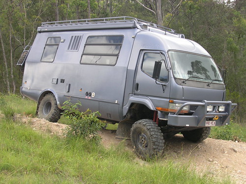
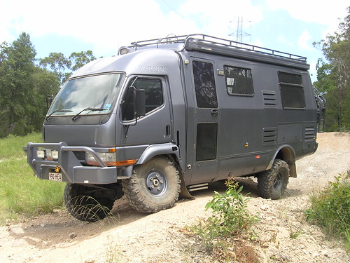
Also here's a couple of twisting pics of an older truck we built that is easy at max GVM. If you look carefully at the main body line down the side of the camper you can see that it doesn't line up with the cab WD. That's the twist going on between the body and cab. We can adjust it for more or less movement but this would be minimum. I know someone asked how much do they flex so that's why I put these pics up.

ntsqd
Heretic Car Camper
There is no such thing as a perfectly rigid frame. Not of any design type, be it a ladder or a space frame. A space frame is more rigid than a ladder, but still is not perfectly rigid, and it greatly interferes with a payload. Anyone who has (foolishly, as I have) stood on a Railroad Truss Bridge has felt something that massive and seemingly rigid flex under the moving load of the train. A RR trestle bridge is a space frame.
So then a ladder frame effectively has a spring rate. In our application where this shows up the most is in crossing obstacles at an angle. Since the distortion is the result of a torque we can think of this as the frame's torsional spring rate.
And since the suspensions also respond to this torque, they too have a torsional spring rate.
When all of those torsional spring rates are near the same value they all move together in response to the twist. The item with the highest torsional spring rate will move the least distance and the item with the lowest torsional spring rate will move the most distance, but all of this happens simultaneously in response to a torsional input.
Only when there is a very, very large difference in torsional spring rates will the lower rate item limit out in distortion before the higher rate item starts to move.
A properly designed domicile box could very likely be rigid enough to be rigidly (as in no pivots of any sort) mounted to the truck's frame and the suspensions would be forced to do all of the torsional displacement absorption, but such a domicile box wouldn't be very accommodating internally as it would very much have to be a space frame.
Last edited:
whatcharterboat
Supporting Sponsor, Overland Certified OC0018
When all of those torsional spring rates are near the same value they all move together in response to the twist. The item with the highest torsional spring rate will move the least distance and the item with the lowest torsional spring rate will move the most distance, but all of this happens simultaneously in response to a torsional input.
Only when there is a very, very large difference in torsional spring rates will the lower rate item limit out in distortion before the higher rate item starts to move.
I knew someone younger and with more brains could actually explain this better than I ever could. Thanks mate. I told you before that they don't pay you enough.
Mickldo
Adventurer
I don't have any experience with FG frames but we do build quite a few service bodies at work on a variety of trucks. Some of them are 4x4 versions but the Electricity provider that we build them for doesn't want pivoting frames and the boss wants to build them as simply and as cheaply as can be done. We build them by the National Code of Practice (NCOP) for Heavy Vehicles.
The NCOP is a typical government document that doesn't tell you want to know because it doesn't have any real content but it does its best to confuse the hell out of you while you try to wade through all the rest.
I can't find much in the NCOP for pivoting mounting systems. They suggest that mounting systems are mounted at an average of 900mm along the chassis rail. That sort of rules out a 3 point system for us.
We use fish plates along the chassis rails every 900mm or so depending on crossmember location. The front of the frame rail is tapered like John was saying earlier. I can't remember what the angle is too off the top of my head. It is some formula that includes the height of the frame rail being used. We also use a wear plate along the top of the chassis rail. At work we use 50 x 10 steel flat bar for the wear plate, which the NCOP allows, instead of a timber wear strip. A lot of the chassis we do have rivets on the top flange so the wear plate goes between the rivet heads. Now this is the bit I don't get, we taper the frame rail but there is a solid bit of 50 x 10 FB with a square end underneath it. I reckon the wear plate needs tapering too.
The fish plates we use are 130 x 10 FB and each one has M16 bolts in 17mm holes with hardened washers and Nyloc nuts. The theory we use is to fully spread the load over the full length of the chassis. Of course the bodies of these vehicles are just Flat Bed Trays with boxes on them so the tray itself is free to twist without damaging anything on the body.
If I was building a camper body that I didn't want to destroy I'd do it differently. I have been toying with the idea of a series of large rubber body mounts mounted along the chassis similar to how a typical Land Cruiser or whatever's body is mounted. I reckon if they were large enough they would be able to support the load of the camper and be able to absorb all (or most???) of the flex of the chassis. It is something I want to look into further.
We are doing a tray on a new Isuzu NPS 300 4x4 at work at the moment. If any of you guys are interested I can take some build photos of how we do it and post them up. Not really relevant to an FG due to the different tray/body designs and different chassis designs but some of you may be interested.
whatcharterboat
Supporting Sponsor, Overland Certified OC0018
Hi Mick, Long time , no see. How ya bin?? How's all the tribe?
I'd be interested. We are doing a new NPS at the moment too. A one off farm truck with some high tech computerized spray equipment. He turned up with his big F650 duallie, full of computer screens and pumps, tanks hoses goin' everywhere. etc. Said he wanted everything swapped over to a new NPS 4x4 with a SRW conversion. So that's what we're doing. Work trucks aren't really our thing. So I don't think you'll ever see us as competition.
To top it all off, this guy has a serious disability and we have to design and build a lift to get him into the cab and another one or two to get him up on the tray at the back. We've got a new FG140 in there at the moment as well so it's a good opportunity to compare the 2 together.
Anyway I don't know for sure how we are mounting the tray yet. Only just got the truck.
Glad your back. I was just thinking that it would be great if you could add something to this thread and there you go. Perfect timing. Good to see you back.
Kerry if you are reading this, I mentioned using wear plates on those pieces of channel so they didn't damage the frame. At work today I noticed the pads that the rear over ride springs sit on. They would be perfect. About the right size and perfect shape. And thought they could maybe go at the bottom of the step near the first crossmember.
We are doing a tray on a new Isuzu NPS 300 4x4 at work at the moment. If any of you guys are interested I can take some build photos of how we do it and post them up. Not really relevant to an FG due to the different tray/body designs and different chassis designs but some of you may be interested.
I'd be interested. We are doing a new NPS at the moment too. A one off farm truck with some high tech computerized spray equipment. He turned up with his big F650 duallie, full of computer screens and pumps, tanks hoses goin' everywhere. etc. Said he wanted everything swapped over to a new NPS 4x4 with a SRW conversion. So that's what we're doing. Work trucks aren't really our thing. So I don't think you'll ever see us as competition.
To top it all off, this guy has a serious disability and we have to design and build a lift to get him into the cab and another one or two to get him up on the tray at the back. We've got a new FG140 in there at the moment as well so it's a good opportunity to compare the 2 together.
Anyway I don't know for sure how we are mounting the tray yet. Only just got the truck.
Glad your back. I was just thinking that it would be great if you could add something to this thread and there you go. Perfect timing. Good to see you back.
Kerry if you are reading this, I mentioned using wear plates on those pieces of channel so they didn't damage the frame. At work today I noticed the pads that the rear over ride springs sit on. They would be perfect. About the right size and perfect shape. And thought they could maybe go at the bottom of the step near the first crossmember.
ntsqd
Heretic Car Camper
If there truly is relative motion between the frame rail and the tray/box frame then I'd want some sort of bushing/bearing material in there, or the ability to grease the entire contact zone. UHMW PE (Ultra High Molecular Weight Poly-Ethylene) is the first material to come to mind. Second would be one of the Acetals like "Delrin".
In a rubber bushing type of mounting, the bushings will need to have enough distortion possible within them to allow for the twist or they will transfer some torsion to the tray/box frame. When I see how much these chassis under discussion twist I don't have high hopes for a rubber bush that can allow half of that distance and still maintain control of the tray/box on a side-hill. Doesn't mean that it's not possible, just that I'm not seeing how it might work.
Yeah John, they don't, but in this economy........
Mickldo
Adventurer
Hi Mick, Long time , no see. How ya bin?? How's all the tribe?
I'd be interested. We are doing a new NPS at the moment too. A one off farm truck with some high tech computerized spray equipment. He turned up with his big F650 duallie, full of computer screens and pumps, tanks hoses goin' everywhere. etc. Said he wanted everything swapped over to a new NPS 4x4 with a SRW conversion. So that's what we're doing. Work trucks aren't really our thing. So I don't think you'll ever see us as competition.
To top it all off, this guy has a serious disability and we have to design and build a lift to get him into the cab and another one or two to get him up on the tray at the back. We've got a new FG140 in there at the moment as well so it's a good opportunity to compare the 2 together.
Anyway I don't know for sure how we are mounting the tray yet. Only just got the truck.
Glad your back. I was just thinking that it would be great if you could add something to this thread and there you go. Perfect timing. Good to see you back.
Kerry if you are reading this, I mentioned using wear plates on those pieces of channel so they didn't damage the frame. At work today I noticed the pads that the rear over ride springs sit on. They would be perfect. About the right size and perfect shape. And thought they could maybe go at the bottom of the step near the first crossmember.
Hi John, it has been a while since I poked my head in here. Been busy playing with the girl. She has gotten to that fun age where she loves to play with Dad so I am lapping it while I can cause I know it won't last forever. When I have been getting online late at night after the girl goes to bed I have been researching a project my mate and I are doing. We have made a foundry and are casting brass bits for his wooden boat he is building. When we finish that we want to make some old motorbike parts for another project we have.
I'll take some photos of the NPS while we are building it. It would be good to see the comparison between the FG and the NPS.
Mickldo
Adventurer
If there truly is relative motion between the frame rail and the tray/box frame then I'd want some sort of bushing/bearing material in there, or the ability to grease the entire contact zone. UHMW PE (Ultra High Molecular Weight Poly-Ethylene) is the first material to come to mind. Second would be one of the Acetals like "Delrin".
In a rubber bushing type of mounting, the bushings will need to have enough distortion possible within them to allow for the twist or they will transfer some torsion to the tray/box frame. When I see how much these chassis under discussion twist I don't have high hopes for a rubber bush that can allow half of that distance and still maintain control of the tray/box on a side-hill. Doesn't mean that it's not possible, just that I'm not seeing how it might work.
Yeah John, they don't, but in this economy........
Yeah I don't know if it would work either but a lot of 4wds use the same system to mount their bodies to the chassis. The amount of twist on an FG might be too much for the design limits of the bush though. They might work on something like the NPS that has a stiffer chassis.
whatcharterboat
Supporting Sponsor, Overland Certified OC0018
Don't have a camera at the moment. Had my all in one phone phone knocked off. So I might just buy a cheap camera so I can post pics again. Nokia Navigator, cost over $800 too. Man, was I happy about that. NOT.
The new FG chassis looks identical to the old one. So body mounting is also unchanged.
As you know the new NPS is totally new from the ground up. Did you know they have the same motor as the new FSS 550 but 550's got about 150 kw. Mate , that means the pump and computer should swap over. How awesome would that be. And still Euro IV spec. The days of hotting up FGs are over with Euro IV but the 550 gear puts a new light on it for the NPS.
Sorry hijaking again.
whatcharterboat
Supporting Sponsor, Overland Certified OC0018
Yeah I don't know if it would work either but a lot of 4wds use the same system to mount their bodies to the chassis. The amount of twist on an FG might be too much for the design limits of the bush though.
Yep.
Mickldo
Adventurer
Don't have a camera at the moment. Had my all in one phone phone knocked off. So I might just buy a cheap camera so I can post pics again. Nokia Navigator, cost over $800 too. Man, was I happy about that. NOT.
The new FG chassis looks identical to the old one. So body mounting is also unchanged.
As you know the new NPS is totally new from the ground up. Did you know they have the same motor as the new FSS 550 but 550's got about 150 kw. Mate , that means the pump and computer should swap over. How awesome would that be. And still Euro IV spec. The days of hotting up FGs are over with Euro IV but the 550 gear puts a new light on it for the NPS.
Sorry hijaking again.
Yeah I knew the NPS was new but I didn't know the 550 had the same motor. That would be a good upgrade as I reckon the NPS is a little doughy down low until the turbo starts to spin up. But then again most of the new Euro IV spec motors are like this.