Power Problem with FM260

JRhetts

Adventurer
Tests, Diagrams, and [?] A Plan

I think gait is getting pretty close to the nub. Nice job from so far away. [Maybe being upside down isn’t really detrimental to one’s thinking ;>} ]

My first diagram below shows the structure and the parts of the overall turbo/waste gate assembly.
1= compressed air line as input to waste gate actuator
2= waste gate actuator housing [not openable, and practically inaccessible]
3= actuator rod
4= waste gate housing
5= waste gate valve arm
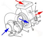
TurboUnit.jpg

My working hypothesis is that it functions like this: increasing pressure thru 1 at some point causes mechanism inside 2 to move arm 3 to operate valve arm 5, which in turns opens the waste gate valve inside 4, which reduces exhaust flow over the turbine blades and lowers overall boost back on the compressor side.


That’s all for now, folks.

John
 
Last edited:

kerry

Expedition Leader
This is what GM6.5 diesel guys often turn to. It's an adjustable turbo waste gate controller. Turn the screw, adjust the poundage at which the gate opens. They do it either because they want more control of the boost or because the vacuum pump which controlled the OE controller failed. In any case, it does what you are planning to do with yours except it uses a spring.

http://heathdiesel.com/performance/turbo-master-gm-boost-control.html
 

gait

Explorer
Edit ... the post I quote below seems to have disappeared. But my bit about how the spring operates is probably still relevant.... also consistent with the adjustable arm in Kerry's link.

.....
Flow/pressure are linearly related unless you are dealing with a VGT turbine.
...

I'm talking of the actuator. There is effectively "no" flow to/from the actuator. Just the very little bit when the spring moves.

Simple feedback control for turbo pressure. The actuator controls the waste gate.

Thus, I'm struggling with the approach to slowing the waste gate response - it would have to be a very small orifice.

John's understood.

Just from first principles ... I'd be a bit careful about adding an "on/off" control in the actuator line at 22psi. The diaphragm simply keeps the actuator air tight, it pushes against the spring. The spring probably introduces a bit of proportional control - the greater the pressure above 22 psi the greater the waste gate valve opening. Put another way, the waste gate is moved to a position that maintains the pressure at 22 psi. More complex than open/closed.

Its the spring in the actuator that provides the control, translates pressure to waste gate position, sets the boost pressure.
 
Last edited:

kerry

Expedition Leader
Not directly related to this problem but I do have a question. Does anyone know the proper boost pressures for a 99 FG. I'm about to install a boost pressure gauge but I have no idea as to what numbers I should be looking for.
 
Regarding the oil analysis:
The Mg is perfectly normal for Rotella T
The Fe is a bit high for <1000 mi but it is well known in oil circles that Fe levels rise the fastest at the beginning of an oil change cycle, partially because of contamination from left over old oil in the engine.
The Pb is worrisome, I would continue to do UOAs (oil analyses) at normal intervals and share them with me/us. You could ask if Mitsubishi would drop your oil pan and check your rod and main bearings under warranty, but they will probably refuse. I don't think it is related to your boost pressure issue.
Charlie
 
Last edited:

mog

Kodiak Buckaroo
Not directly related to this problem but I do have a question. Does anyone know the proper boost pressures for a 99 FG. I'm about to install a boost pressure gauge but I have no idea as to what numbers I should be looking for.
On page 13E-41 of the FG shop manual it shows the max reading (4.5v) for the factory pressure sensor to be: 163.7 kPa {48.4 in. Hg, 1230 mmHg}
or 23.77 psi. So something under, but close to that I would guess.
-
BTW- that is assuming you are starting with a standard pressure (atmospheric) pressure of 100 kPa {29.9 in. Hg, 760 mmHg} or 14.68 psi at 25' C (77' F).
 
Last edited:

mog

Kodiak Buckaroo
John,
If line (1) is accessible why don't you just add a pressure regulator inline (Mini regulator w/gauge) for troubleshooting/testing.
You can monitor your 'real' boost via your already installed turbo boost (pressure) gauge and control (bias) the pressure to the wastegate via the regulator, monitoring that line pressure by the gauge on the regulator.
That way you won't fault the ECU.
boost-reg.jpg
 

JRhetts

Adventurer
John,
If line (1) is accessible why don't you just add a pressure regulator inline (Mini regulator w/gauge) for troubleshooting/testing.
You can monitor your 'real' boost via your already installed turbo boost (pressure) gauge and control (bias) the pressure to the wastegate via the regulator, monitoring that line pressure by the gauge on the regulator.
That way you won't fault the ECU.

mark

I have thought of this solution several times, but I keep hitting a mental dead end. If I understand how this regulator works [which I well may not!], lets suppose it is accurately set for 22 psi. When pressure greater than this arrives it will restrict or neck down to maintain that set point. So this would keep the Actuator from ever working to moderate high levels of boost when the turbo creates them and passes them onto the intake manifold. Have I got this right? If so, then I have lost all negative feedback control of over boost, which I now know does occur [assuming my gauge is accurate.] [The ECU certainly thinks so, tho the electronic boost sensor too might benefit from more accurate calibration.]


John
 
Last edited:

kerry

Expedition Leader
The FG has some kind of overboost blow off valve in the intake manifold. Could you use one of those?
 

JRhetts

Adventurer
The FG has some kind of overboost blow off valve in the intake manifold. Could you use one of those?

Hell YES. Seems like that might solve all my problems in a simple way, unless of course that would unintentionally lead to a battle between the waste gate and the intake manifold valve!?

i have some information that the newer FMs than mine have a boost adjust right on the side of the compressor half of the turbocharger. Sure would like something like that.

John
 

Amesz00

Adventurer
mark

I have thought of this solution several times, but I keep hitting a mental dead end. If I understand how this regulator works [which I well may not!], lets suppose it is accurately set for 22 psi. When pressure greater than this arrives it will restrict or neck down to maintain that set point. So this would keep the Actuator from ever working to moderate high levels of boost when the turbo creates them and passes them onto the intake manifold. Have I got this right? If so, then I have lost all negative feedback control of over boost, which I now know does occur [assuming my gauge is accurate.] [The ECU certainly thinks so, tho the electronic boost sensor too might benefit from more accurate calibration.]

In my twisted thinking, I come back to the notion that what I need is a valve that stays closed [nothing to the Actuator] until the set point [22 psi] and then it opens and lets 100% thru to operate the Actuator and bring things back down to the set point.

Have I got this wrong? I know darn well I may have!!

John

John,

the link to the little blue device i posted earlier, is for that exact application. its a manual boost controller. you would put it in the actuator line, then adjust to the boost you want (in this case 22psi). it works by a teeny tiny hole that bleeds out excess pressure, up to the setpoint, after that air pushes past the spring and into the actuator.
im still not convinced that the turbo is the real source of the power loss. as i have said, if it was getting the same fuel, but 18% less air (due to say a wastegate malfunction) then it would just run 18% richer... but would make similar power figures.
 

gait

Explorer
For 4D34 Engine in 2005 FG Australia, section E15 page 7 of manual. Boost pressure standard value "-", limit 36kPa (270mm Hg) at 3700 rpm, no load, air temp 20 deg C, air pressure 100 kPa (760mm Hg). Correction required for different air temp and rpm deviation. Nothing about altitude or other atmospheric pressure correction.

By my calculation 36kPa is about 5.2 psi. Doesn't say if its relative (to atmosphere) or absolute pressure. Possible clue is ECU code 32 which suggests ECU assumes 0 and goes into limp when outside limits (>0.5v or > 4.8v) so 36 kPa is probably relative.

I don't have a boost gauge but its high on agenda.

Interesting perhaps for John - under "Remedy" the manual says "Inspect and adjust". Nothing anywhere else about how to adjust.
 

JRhetts

Adventurer
Interesting perhaps for John - under "Remedy" the manual says "Inspect and adjust". Nothing anywhere else about how to adjust.

Yeah, I saw that too. I spent more than an hour trying to cross check where they described how/where to "Inspect/adjust".

After familiarizing myself with the physical plant quite a bit, I can't find anything even remotely plausible that would permit either inspection or adjustment. But I sure could be missing something.

John
 

kerry

Expedition Leader
That thread I linked states that at least the 4DB4 turbo is sold as a unit by Fuso with the actuator and the actuator is not sold separately. Maybe the same with the FM.
 

Forum statistics

Threads
185,944
Messages
2,880,087
Members
225,627
Latest member
Deleman
Top