jscherb
Expedition Leader
Part 1
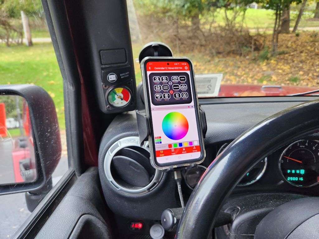
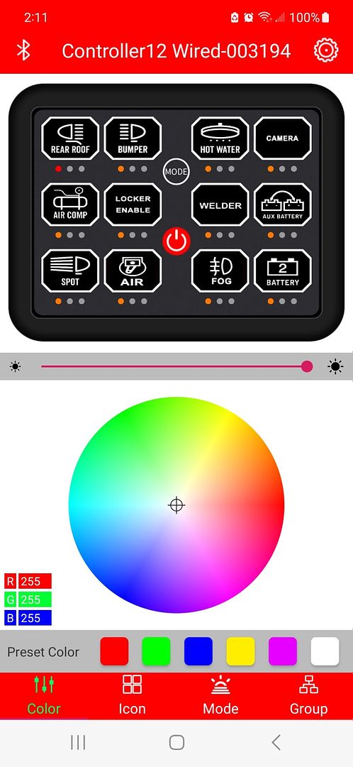
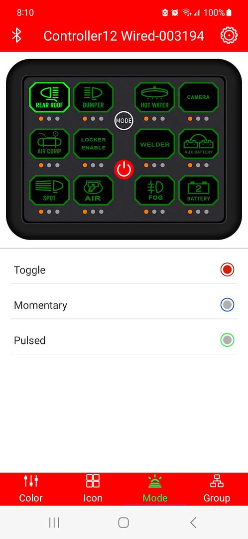
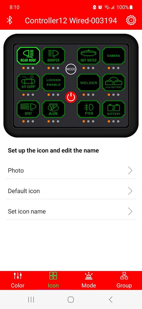
Recently Auxbeam upped the game in switch panels when they released their new 12-gang panel. It's got a Bluetooth interface to a smartphone app, a handheld remote control, and 100 amps total capacity.
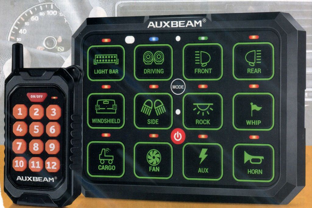
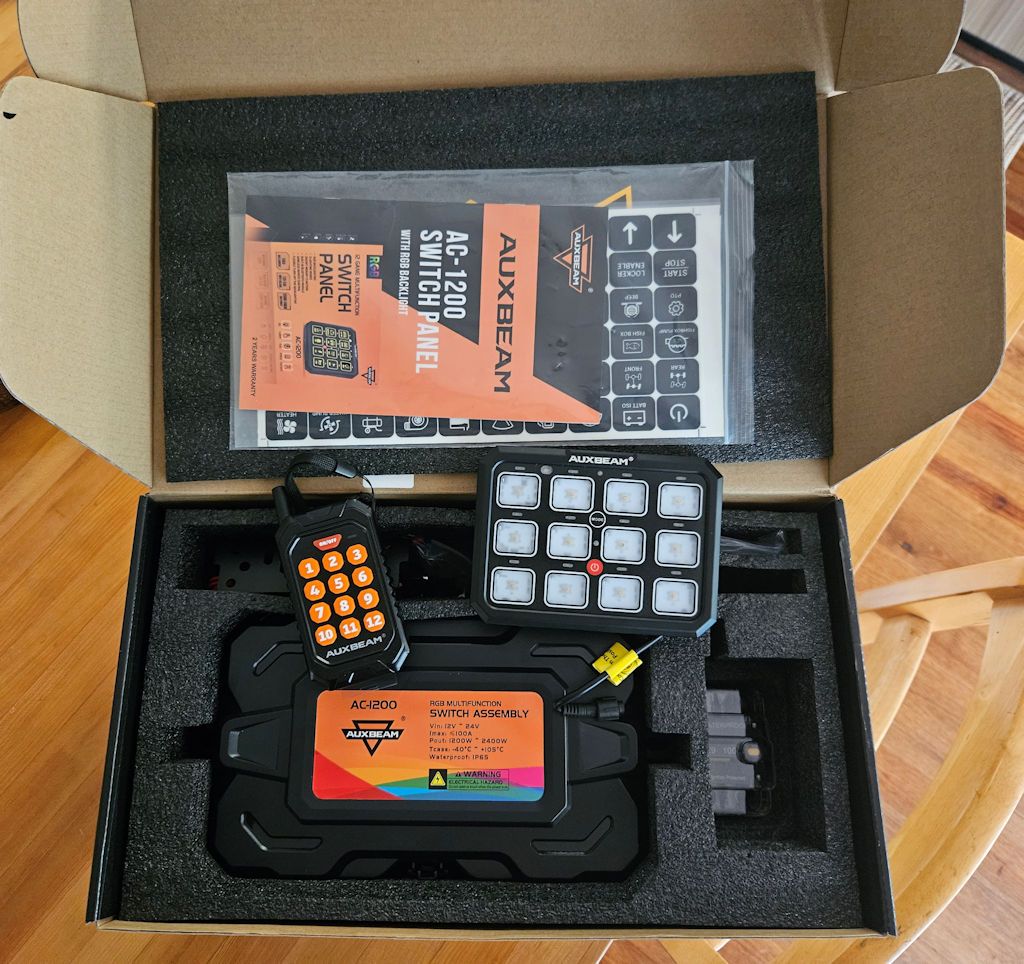
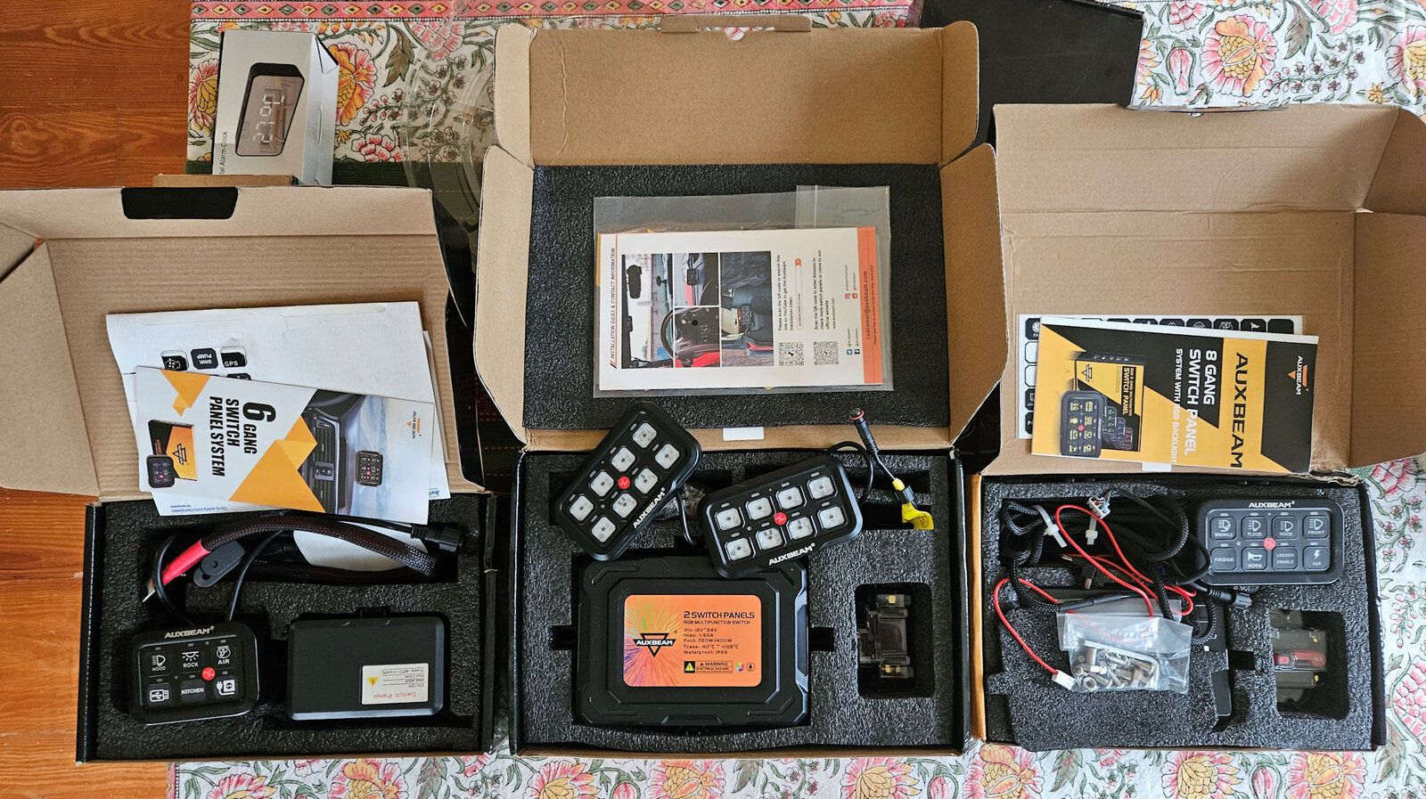
A few weeks ago they sent me one to test and review. The kit includes the switch panel, a handheld remote, the control unit, a 100amp circuit breaker, and various mounting brackets, wiring and other hardware.
I did test installs in both my LJ and my JKU; what follows is the JK installation. If anyone is interested in the details of the TJ installation I can share that as well.
Installing the Auxbeam AC-1200 Switch Panel in a JK Wrangler
Installing the Auxbeam AC-1200 switch panel involves a number of steps:
Mounting the Control Box
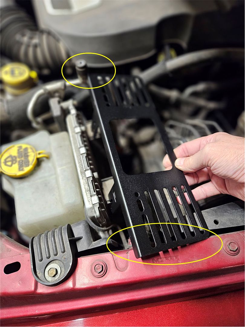
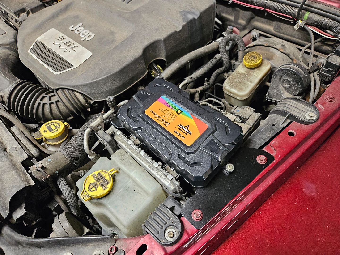
Unfortunately, the mounting bracket provided with the AC-1200 12-gang switch panel system is just too long to fit in what is probably the only place in the engine compartment that the large control box for the system can be installed. In the photo below you can see that it’s too long – it overhangs the fender and on the other end it interferes with one of the hard A/C lines.
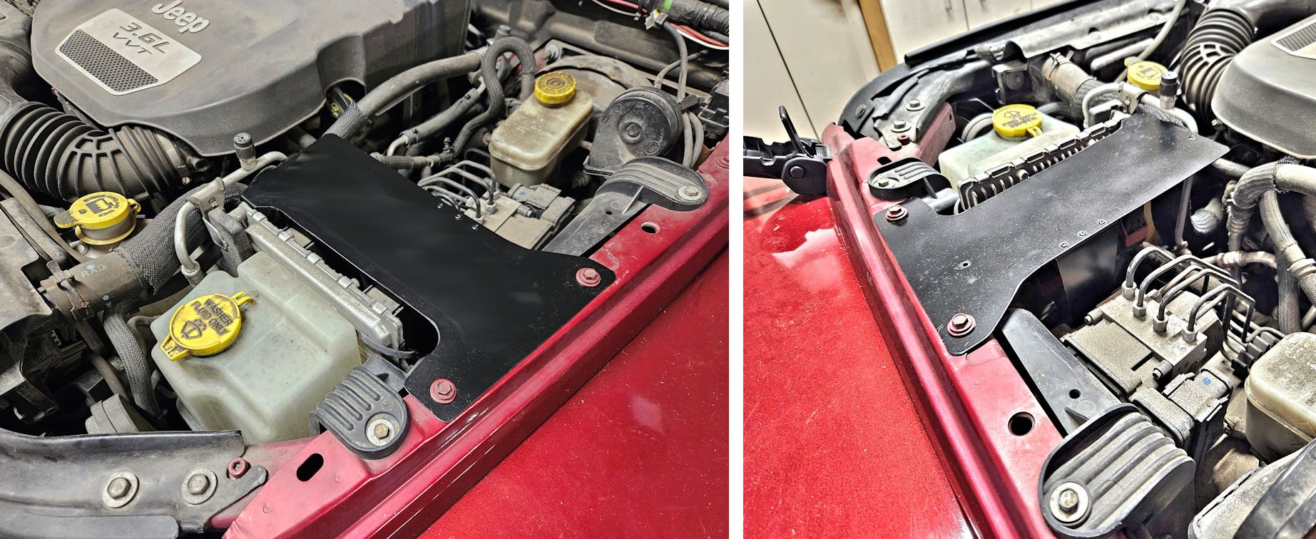
The location shown in the photo above is really the best place to mount the large AC-1200 control box in the crowded JK engine compartment and since the mounting bracket that Auxbeam supplies with the kit just doesn’t work in that location, I made my own. If anyone needs the pattern to make a similar bracket let me know and I can share it. The new bracket:
Powering The Control Box
There are two power connections to the control box – switched power to operate the box, and higher current power to operate any accessories connected to the system.
Auxbeam supplies heavy-gauge cables to connect the control box to the Jeep’s battery to power accessories connected to the system. Unfortunately since the best place to install the control box is further away from the battery than the length of the supplied cables. Longer cables must be used, and they must be of a gauge heavy enough to carry the 100 amps of current that the control box is capable of supplying to accessories.
A good way to make new cables is to start with a set of jumper cables. Stores like Walmart offer relatively inexpensive jumper cables which are an excellent source of the require wire – this set offers 4-gauge wire and retails for less than $20: https://www.walmart.com/ip/Everstar...motive-Booster-Cables-Jumper-Cables/182918724. Those cables are 20 feet long; only about 6 feet will be required to connect the control box to the battery so if you remove one of the clamps from the jumper cables, cut 6’ of wire from the 20’ and reinstall the clamps you will end up with a 14’ set of jumper cables and enough wire to connect the control box.
Also needed will be 4 ring terminals to terminate each end of the 6’ cables. Auto parts stores like AutoZone and many electrical supply stores offer ring terminals like those shown below – the accept 4-gauge wire and have a 3/8” I.D. ring which is perfect for connecting to the control box and the battery.

A completed cable to connect the control box to the battery made from part of a set of jumper cables can look like the one in the photo below. Red heat-shrink tubing has been added to one of the wires to indicate that it is the positive connection; black heat shrink tubing has also been shrunk over the ring terminals to protect them. The heat shrink tubing isn’t strictly necessary but it makes for a more professional looking cable.
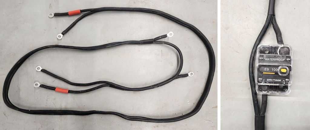
There’s a break in the positive side of the cable with terminals on each end of the break, that’s where the circuit breaker will be inserted into the circuit, as shown in the photo at right.
Supplying Operating Power to the Control Box
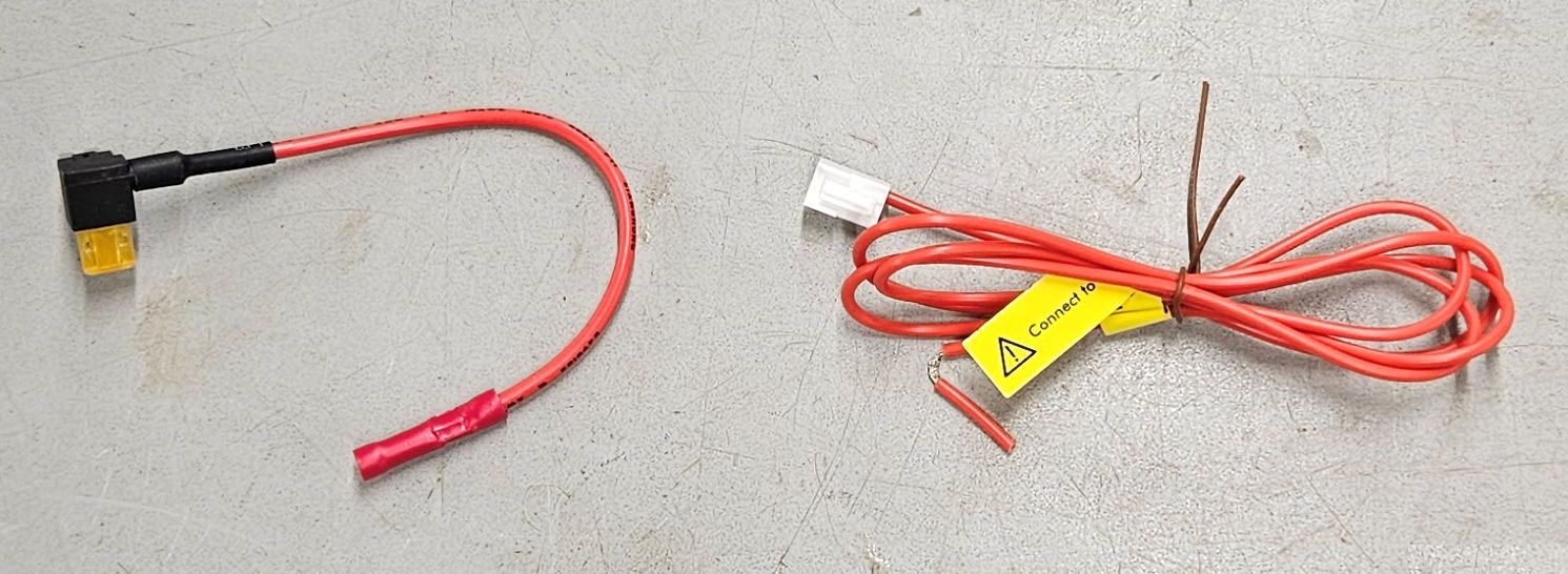
The kit came with two fairly short wires for connecting power to the control box. One piece has a fuse adapter on it and the other piece has a plug for the control box. The fuse adapter makes it easy to supply switched power to the control box, but additional wire will be required in almost all installations to connect between these two pieces. Wiring option 1:
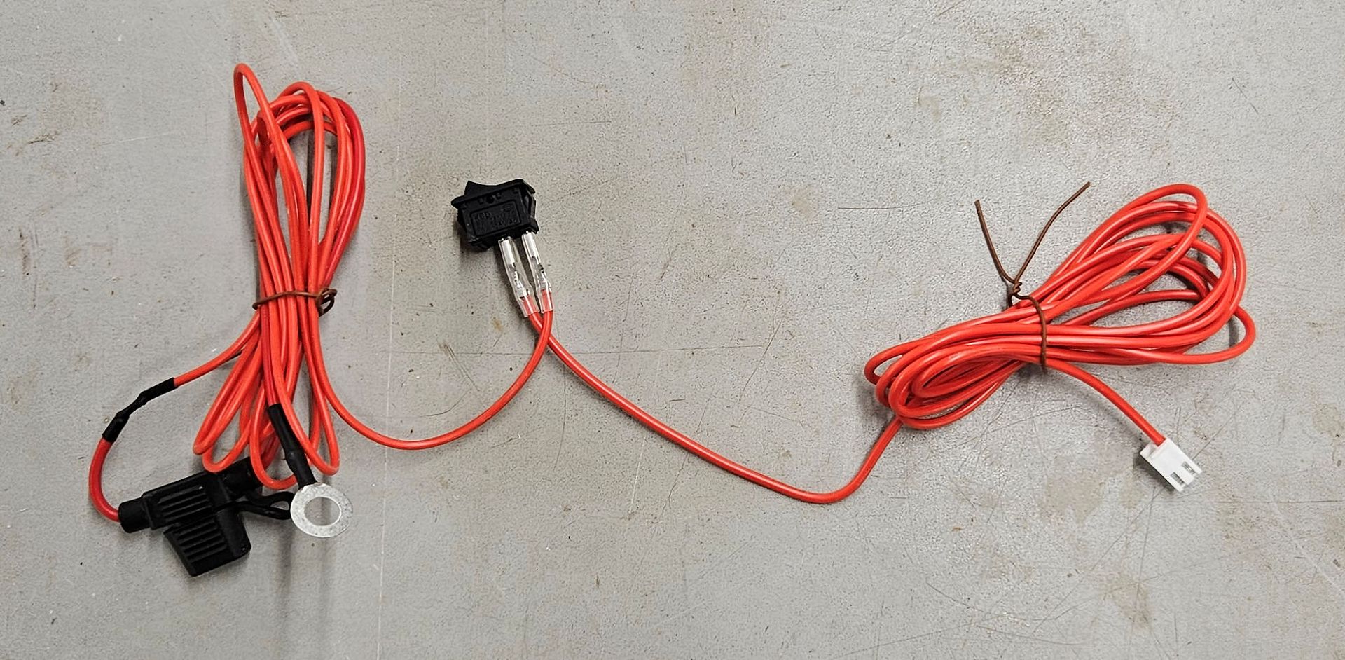
When I met with Auxbeam at the SEMA Show, they gave me an alternate wiring solution. This one has a ring terminal on one end for direct connection to the battery and an inline fuse, a plug on the other end for the control box, and a switch in the middle for turning power to the control box on or off. The wires are long enough for most installations. This solution might be better for a camping/overlanding vehicle in which accessories might need to be powered at the campsite when the vehicle isn’t running, but one must remember to turn the switch off if the system isn’t to be used when the engine isn’t running. Or, the ring terminal can be removed and that end of the wire can be connected to a switched circuit if the system isn’t to be used when the engine isn’t running. Wiring option 2:
Whichever wiring solution your kit comes with, both wiring solutions have their benefits and drawbacks but either one will work fine in most implementations.
Wiring option 1:
The other power connection required goes to the Jeep’s fuse panel and provides switched power to operate the system. Switched power is power that’s only active when the ignition switch is in the on/run position and is recommended so the system doesn’t draw power when the engine isn’t running, which might drain the battery.
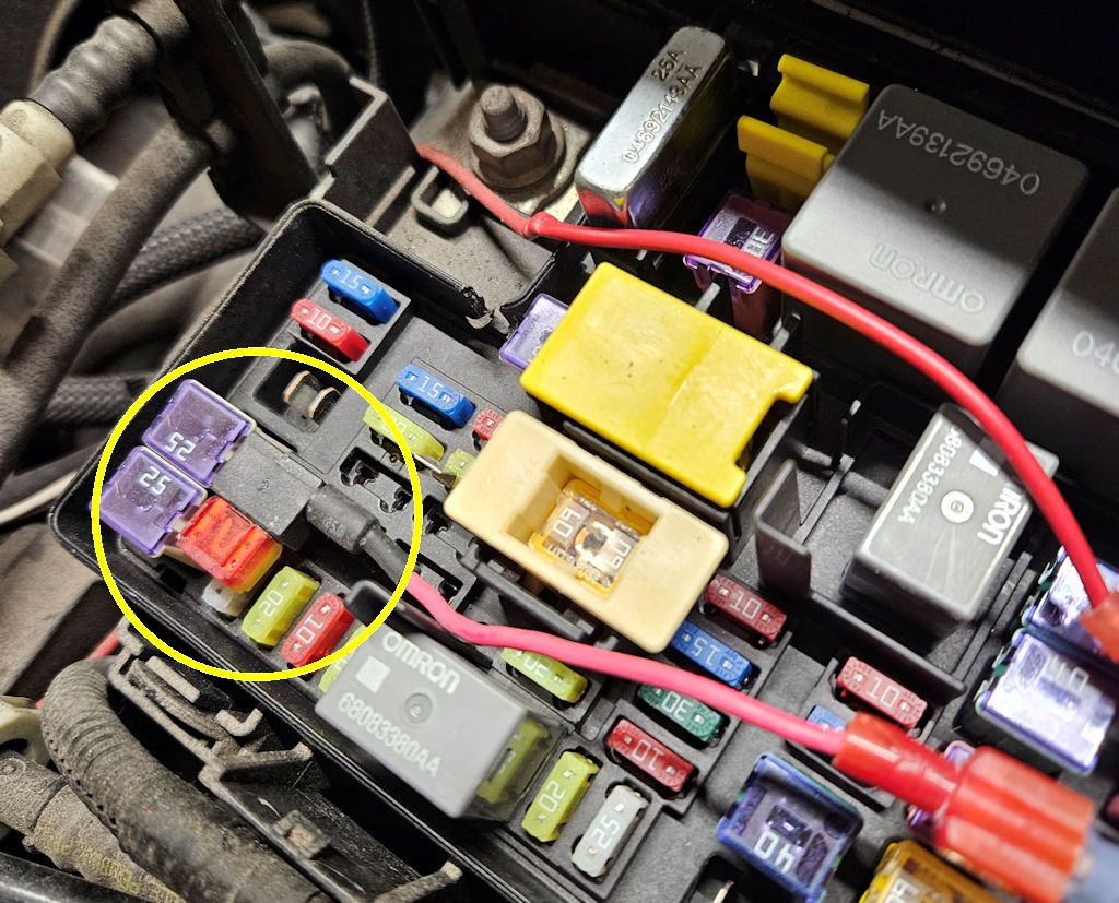
In a JK Wrangler, switched power can be sourced in the “TIPM”, which is Jeep’s term for the fuse box in the engine compartment. TIPM stands for Totally Integrated Power Module, and inside it is a lot more than just the fuse panel, but for our purposes for this installation all we care about is the fuse panel.
Auxbeam supplies a fuse adapter with the kit; remove the fuse from position M7 in the fuse panel, plug the fuse tap into that position and insert the fuse removed from position M7 into the open slot in the fuse tap and shown in the photo below. Fuse M7 protects the auxiliary power outlet in the Jeep, and since it’s switched power (although this can be overridden to constant power in some models with a dash setting) it’s a good place to provide power to operate the switch panel system. Note: verify that the setting for this circuit is switched power, not constant. Using constant power for the operation of the switch panel system isn’t recommended because it could drain the battery when the engine isn’t running.
Auxbeam provides a short length of red wire with a two-pin plug on one end, this plug goes into a two-pin location inside the control box. The other end of this red wire must connect to the loose end of the fuse tap installed above, and an extra length of red wire is required because the combination of the fuse tap wire and the control box wire is too short to reach between them. Auto parts stores sell red 16-gauge wire for this purpose.
Wiring option 2:
With the second wiring option, the ring terminal is connected to the positive terminal of the battery, and the wires that connect to the switch get routed through the firewall as will be described below; the switch can be mounted in any convenient place on or under the dash. The switch is used to control power to operate the system and should be switched off when the Jeep isn’t running.
Recently Auxbeam upped the game in switch panels when they released their new 12-gang panel. It's got a Bluetooth interface to a smartphone app, a handheld remote control, and 100 amps total capacity.
A few weeks ago they sent me one to test and review. The kit includes the switch panel, a handheld remote, the control unit, a 100amp circuit breaker, and various mounting brackets, wiring and other hardware.
I did test installs in both my LJ and my JKU; what follows is the JK installation. If anyone is interested in the details of the TJ installation I can share that as well.
Installing the Auxbeam AC-1200 Switch Panel in a JK Wrangler
Installing the Auxbeam AC-1200 switch panel involves a number of steps:
- Mounting the control box
- Powering the control box
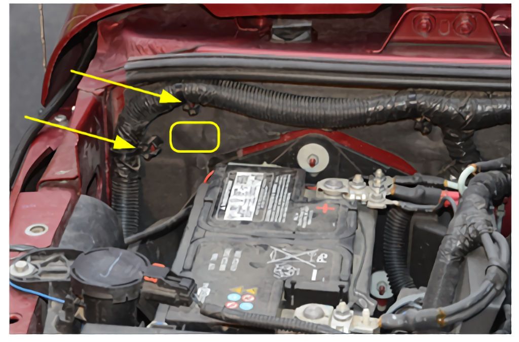
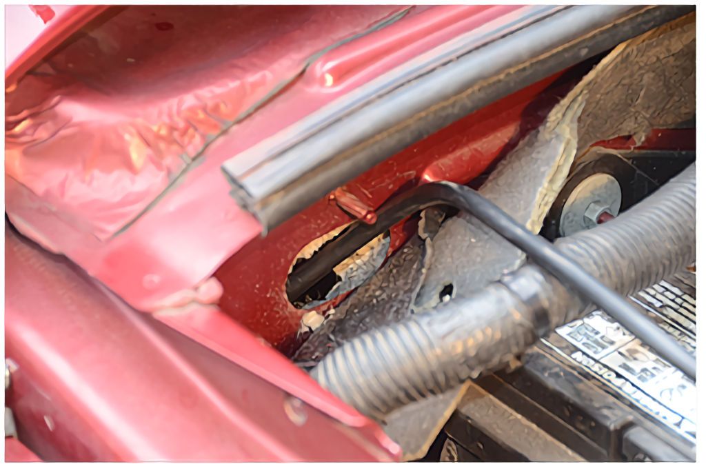
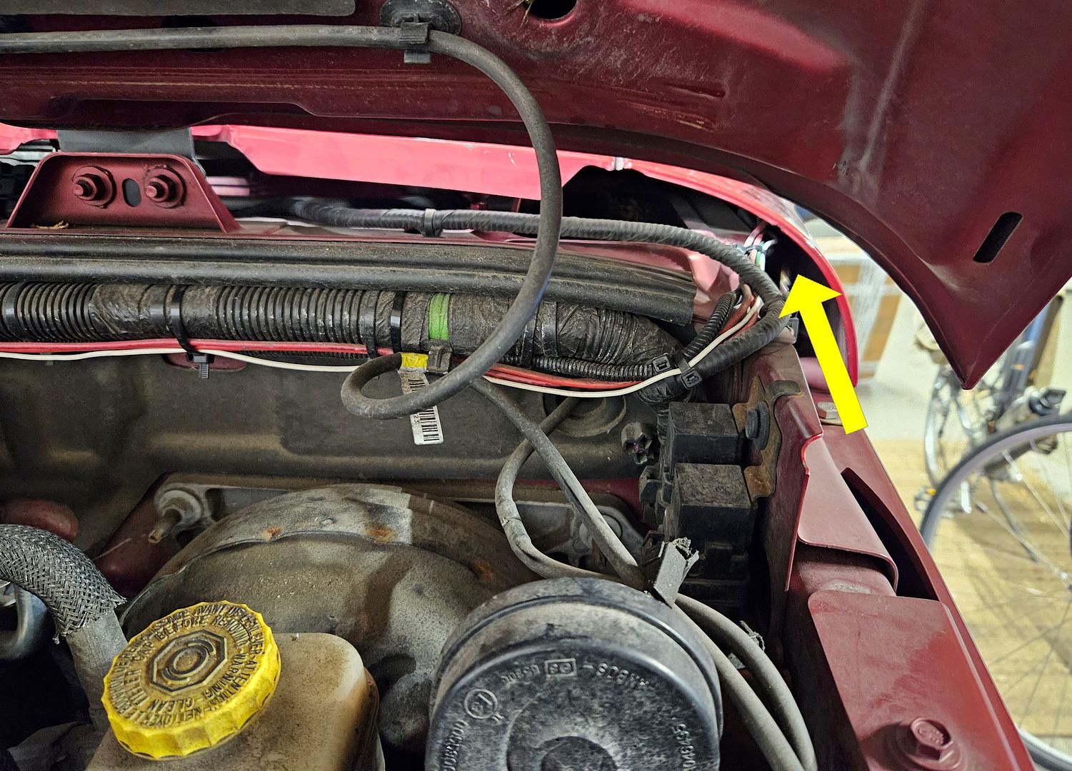
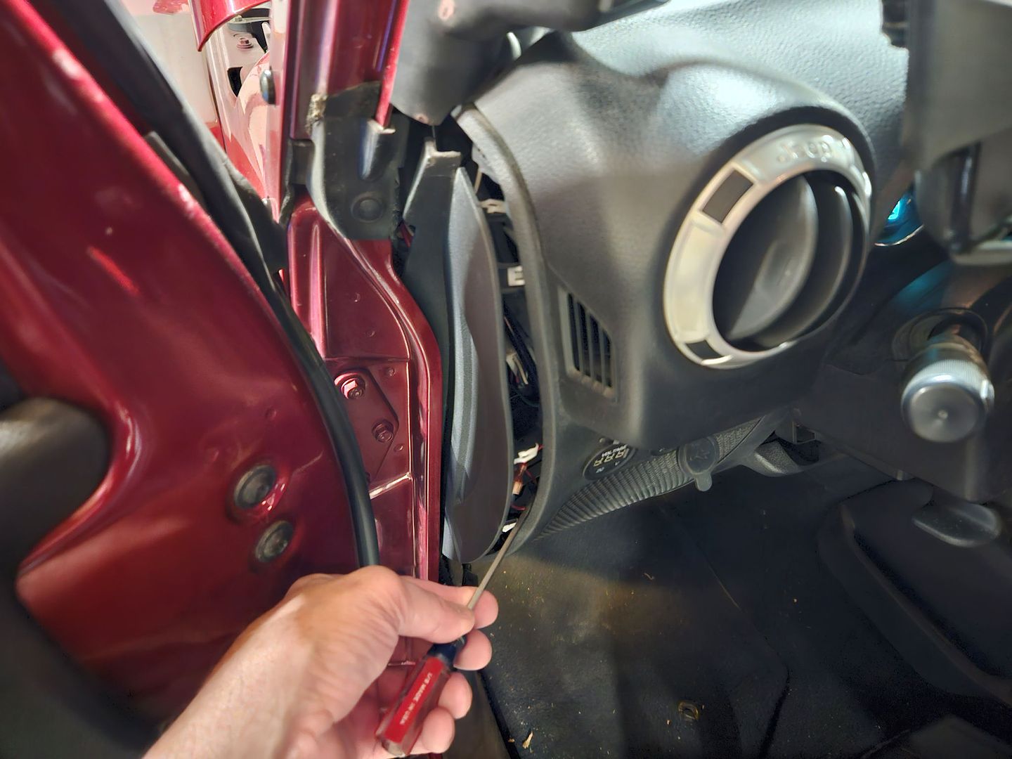
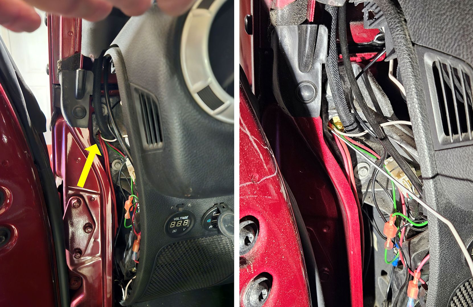
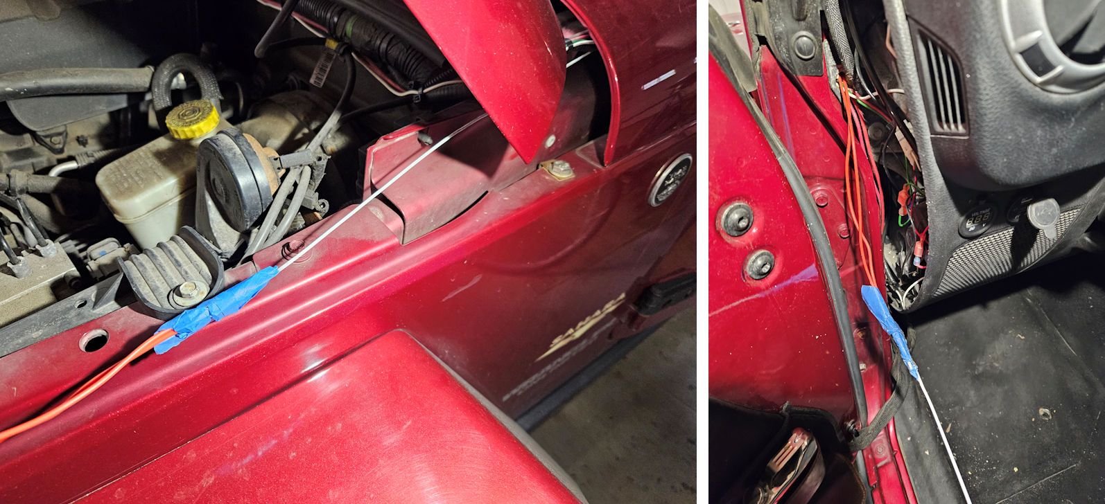
- Connecting the switch panel to the control box through the firewall
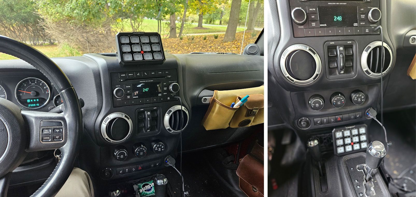
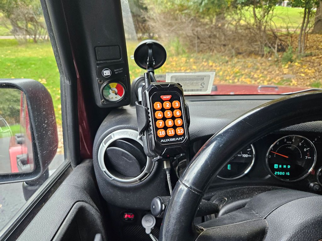
- Mounting the switch panel in the cockpit
Mounting the Control Box
Unfortunately, the mounting bracket provided with the AC-1200 12-gang switch panel system is just too long to fit in what is probably the only place in the engine compartment that the large control box for the system can be installed. In the photo below you can see that it’s too long – it overhangs the fender and on the other end it interferes with one of the hard A/C lines.
The location shown in the photo above is really the best place to mount the large AC-1200 control box in the crowded JK engine compartment and since the mounting bracket that Auxbeam supplies with the kit just doesn’t work in that location, I made my own. If anyone needs the pattern to make a similar bracket let me know and I can share it. The new bracket:
Powering The Control Box
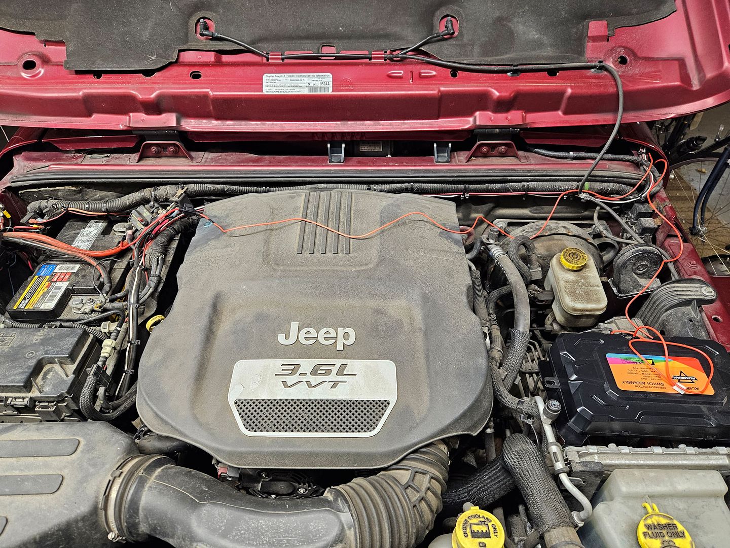
There are two power connections to the control box – switched power to operate the box, and higher current power to operate any accessories connected to the system.
Auxbeam supplies heavy-gauge cables to connect the control box to the Jeep’s battery to power accessories connected to the system. Unfortunately since the best place to install the control box is further away from the battery than the length of the supplied cables. Longer cables must be used, and they must be of a gauge heavy enough to carry the 100 amps of current that the control box is capable of supplying to accessories.
A good way to make new cables is to start with a set of jumper cables. Stores like Walmart offer relatively inexpensive jumper cables which are an excellent source of the require wire – this set offers 4-gauge wire and retails for less than $20: https://www.walmart.com/ip/Everstar...motive-Booster-Cables-Jumper-Cables/182918724. Those cables are 20 feet long; only about 6 feet will be required to connect the control box to the battery so if you remove one of the clamps from the jumper cables, cut 6’ of wire from the 20’ and reinstall the clamps you will end up with a 14’ set of jumper cables and enough wire to connect the control box.
Also needed will be 4 ring terminals to terminate each end of the 6’ cables. Auto parts stores like AutoZone and many electrical supply stores offer ring terminals like those shown below – the accept 4-gauge wire and have a 3/8” I.D. ring which is perfect for connecting to the control box and the battery.
A completed cable to connect the control box to the battery made from part of a set of jumper cables can look like the one in the photo below. Red heat-shrink tubing has been added to one of the wires to indicate that it is the positive connection; black heat shrink tubing has also been shrunk over the ring terminals to protect them. The heat shrink tubing isn’t strictly necessary but it makes for a more professional looking cable.
There’s a break in the positive side of the cable with terminals on each end of the break, that’s where the circuit breaker will be inserted into the circuit, as shown in the photo at right.
Supplying Operating Power to the Control Box
The kit came with two fairly short wires for connecting power to the control box. One piece has a fuse adapter on it and the other piece has a plug for the control box. The fuse adapter makes it easy to supply switched power to the control box, but additional wire will be required in almost all installations to connect between these two pieces. Wiring option 1:
When I met with Auxbeam at the SEMA Show, they gave me an alternate wiring solution. This one has a ring terminal on one end for direct connection to the battery and an inline fuse, a plug on the other end for the control box, and a switch in the middle for turning power to the control box on or off. The wires are long enough for most installations. This solution might be better for a camping/overlanding vehicle in which accessories might need to be powered at the campsite when the vehicle isn’t running, but one must remember to turn the switch off if the system isn’t to be used when the engine isn’t running. Or, the ring terminal can be removed and that end of the wire can be connected to a switched circuit if the system isn’t to be used when the engine isn’t running. Wiring option 2:
Whichever wiring solution your kit comes with, both wiring solutions have their benefits and drawbacks but either one will work fine in most implementations.
Wiring option 1:
The other power connection required goes to the Jeep’s fuse panel and provides switched power to operate the system. Switched power is power that’s only active when the ignition switch is in the on/run position and is recommended so the system doesn’t draw power when the engine isn’t running, which might drain the battery.
In a JK Wrangler, switched power can be sourced in the “TIPM”, which is Jeep’s term for the fuse box in the engine compartment. TIPM stands for Totally Integrated Power Module, and inside it is a lot more than just the fuse panel, but for our purposes for this installation all we care about is the fuse panel.
Auxbeam supplies a fuse adapter with the kit; remove the fuse from position M7 in the fuse panel, plug the fuse tap into that position and insert the fuse removed from position M7 into the open slot in the fuse tap and shown in the photo below. Fuse M7 protects the auxiliary power outlet in the Jeep, and since it’s switched power (although this can be overridden to constant power in some models with a dash setting) it’s a good place to provide power to operate the switch panel system. Note: verify that the setting for this circuit is switched power, not constant. Using constant power for the operation of the switch panel system isn’t recommended because it could drain the battery when the engine isn’t running.
Auxbeam provides a short length of red wire with a two-pin plug on one end, this plug goes into a two-pin location inside the control box. The other end of this red wire must connect to the loose end of the fuse tap installed above, and an extra length of red wire is required because the combination of the fuse tap wire and the control box wire is too short to reach between them. Auto parts stores sell red 16-gauge wire for this purpose.
Wiring option 2:
With the second wiring option, the ring terminal is connected to the positive terminal of the battery, and the wires that connect to the switch get routed through the firewall as will be described below; the switch can be mounted in any convenient place on or under the dash. The switch is used to control power to operate the system and should be switched off when the Jeep isn’t running.


") . BTW people on that forum are enthusiastic owners of the MORryde tailgate reinforcement, which is why I got involved over there - to answer questions people might have about the use of my design.
. BTW people on that forum are enthusiastic owners of the MORryde tailgate reinforcement, which is why I got involved over there - to answer questions people might have about the use of my design.