The evolution of "Alpine" Tundra

RoundOut

Explorer
Battery Relocation Phase II - Cable routing

Wow, we got the hardest part started today. I have been concerned about routing the cable the safest way, since failure is not an option. We picked up some blue plastic conduit from Home Depot, along with some cool cable mounts. O'Rielly's had the coolest heat shrink I've ever used... it sort of reminded me of Mick Dundee, "That's not heat shrink, now this is heat shrink!" It starts out about an 1.25 - 1.5 inches in diameter and shrinks down to 3/8", with glue. We also employed two 3' lenghts of silicone starter cable protective cover from Smileys. Other materials used today included two 25' lengths of 2/0 battery cable, one in black and one in red, along with a few dozen zip ties.

Here's how it went...

Getting the cable into the conduit and into the silicone sleeve was interesting. We cut the 25' conduit in half to use some for each polarity of cable, and then put one end in the pipe holder of a bench vise. The stuff is pretty rigid, so we straightened it out and started feeding the black cable. We got the black cable into the conduit with brute force and twisting of the cable while holding the conduit fixed straight out. The red cable was not as easy. Finally I put some dish detergent in the conduit on the vise end and chased it with about a cup of water and allowed gravity to do its thing. I wish we had done this on the black, because it was a snap after that. We left about 18" of cable exposed on the box end of each cable. In the front, we pulled it back out and soaped up the silicone sleeve. We worked it on the cable slowly by sliding it together and then stretching it out, repeating this process until it was where we wanted it. After the sleeve was on, we used the red and black heat shrink from O'Reily's to seal up this joint tight. The funny part about using all the soap, was that when it dried, our hands picked up a ton of dirt, but later when we went to wash them off, they cleaned up without any additional soap. LOL

Next, we identified a route down the right side frame, just inside the rail from the battery box forward to just inside the wheelwell in the front right. I was concerned about heat near the headers, as the cables run within about 6" of them. We used the silicone ignition cable sleeves from this point down about 4" past the catalytic converters, where the blue plastic conduit picked up. I heat shrinked a water tight seal at this joint, after slitting the plastic conduit about 1/2" on the end to cover about 1/2" of silicone sleeve. The glue oozed out the end, so it looks like we got a great seal.

When it comes to cable routing, it sure helped having two of us. Starting from the front, we layed out the cable in front of the truck and fed it down behind the ABS controller, down the space closest to the corner of the firewall and rear of the right wheelwell, and over a cross-member, staying as far away from the exhaust as possible, and pulled the slack to the floor. With the truck lifted just about a foot, my buddy David got down on the crawler to pull from below while I fed from above. We then lifted the truck and after pulling all the cable down the rail in the most appropriate spots, we dropped the truck down again and fed it back about two feet more backwards, to allow me to easily add some split loom for the cable in the engine end and wrap it with electrical tape from the point where the silicone cover ended close to the other end. After wrapping it, we fed it back down to its desired location with the silicone protective sleeve in the areas closest to the headers and catalytic converter.

We had about an hour left before having to get cleaned up for dinner, so we zip tied the cable in place, leaving the rest for the next day, hopefully Saturday night. My son and I are headed to Huntsville State Park with some friends to do some mountain biking on the trails, and then have to be back to attend one of his buddies' Eagle Scout Court of Honor.

Here are some pics of today's efforts...
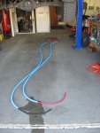
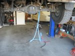
  1. The cable layed out on the floor after putting it into the blue conduit. Note the soapy water oozing from the red cable.
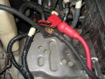
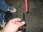
  2. Getting ready to put the silicone sleeve on the red cable.
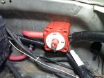
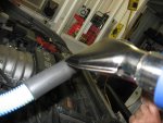
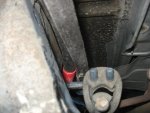
  3. Heat shrinking the joint between the plastic conduit and the silicone sleeve.
  4. The heat gun is the right tool for this job!
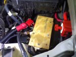
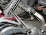
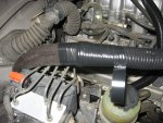
  5. Feeding cable down the route in the corner of the engine bay near the ABS controller.
  6. View from below, just behind the engine on the right frame rail as we fed the cable.
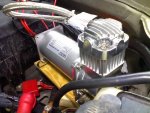
  7. Cable route near the catalytic converter. Don't worry, we zip tied these to the frame as far from the catalytic converter as possible. Also, this blue conduit is much farther back and the silicone sleeve protects it here after the final pull of cable.
 

Attachments

  • IMG_2479.JPG
    IMG_2479.JPG
    565.6 KB · Views: 35
  • IMG_2484.JPG
    IMG_2484.JPG
    498 KB · Views: 26
  • IMG_2485.JPG
    IMG_2485.JPG
    429.1 KB · Views: 27
  • IMG_2486.JPG
    IMG_2486.JPG
    499.3 KB · Views: 26
  • IMG_2487.JPG
    IMG_2487.JPG
    486.6 KB · Views: 25
  • IMG_2492.JPG
    IMG_2492.JPG
    426 KB · Views: 23
  • IMG_2491.JPG
    IMG_2491.JPG
    412.3 KB · Views: 24
Last edited:

RoundOut

Explorer
Battery Relocation Phase II - Cable routing - more pics

One other project that I did yesterday, was to use RTV to seal the solenoid for water crossings.

Here are some addition pics of the cable routing project...
  1. Ewe, tenticles!
  2. My best friend, David, lowering the truck after zip tying the cables in place and replacing the skid plate. We sure enjoy tinkering with our cars and trucks, and it sure helps having a great shop to do it in. Thanks, David!
  3. Starting a good wrap of electrical tape on the split loom from where the silicone sleeve ends to the engine end of the cable. We used 25' of red and 25' of black cable and may have as much as three extra feet at the back end. It is not yet finally zip tied in place, so if I needed to tweak it by a few inches, we still can. However, it looks like the length toward the orignal battery location will be PERFECT! Yippee.:Mechanic:
 

Attachments

  • IMG_2490.JPG
    IMG_2490.JPG
    611.1 KB · Views: 40
  • IMG_2489.JPG
    IMG_2489.JPG
    578.2 KB · Views: 47
  • IMG_2488.JPG
    IMG_2488.JPG
    673.5 KB · Views: 39
Last edited:

keezer36

Adventurer
Thank you for the wonderful write-up on the dual batteries. I've been planning mine out this past week so this came in handy. I now know about silicone sleeves.

How will you be using your batteries? That is, will one be isolated solely as a back-up or will you have add-on accessories constantly feeding off it while the other tends to the cranking and factory accessories?

I don't know if you've seen these yet, but thought I'd make mention of them as you may find them to be better than grommets with regards to water intrusion as a pass-thru to your box: http://bluesea.com/category/9/productline/overview/11
 

RoundOut

Explorer
Thanks for the kind words, Keezer.

keezer36 said:
How will you be using your batteries? That is, will one be isolated solely as a back-up or will you have add-on accessories constantly feeding off it while the other tends to the cranking and factory accessories?
I plan to have it exclusively as a backup until such point as I get a fridge.

keezer36 said:
I don't know if you've seen these yet, but thought I'd make mention of them as you may find them to be better than grommets with regards to water intrusion as a pass-thru to your box: http://bluesea.com/category/9/productline/overview/11

Those are awesome and I'm going to get some. Thanks a bunch. If nothing else, for the strain relief. Unfortunately, I've already punched four 7/8" holes, so unless I can fill them somehow and still use these, I may be hosed there.

.
 

jim65wagon

Well-known member
devinsixtyseven said:
Gary this is looking so cool! Can't wait to see everything all hooked up...or better yet, see it in person :p.

agreed! maybe you'll need to make an around the country circuit to show everyone...Gary's 49 state tour!
 

RoundOut

Explorer
Dual batteries relocated! More pics.

Almost done with this mod. Before our Scout campout this past weekend, we finished up relocating the primary to the rear and mounting the terminal posts to the front in its place. I didn't have time to finish installing the Blue Sea lockout switch, and I am thankful for that -- read on...

When preparing for this work, I researched and learned that the best polarity to lock out was the negative pole. Following this learned advice, I was planning on installing the lockout on the negative lead up near the engine in the OEM battery location. However, when routing the leads forward, I chose to ground the negative lead, and run it through the rear battery box, in the same location. This provided an effective ground to the frame, but after reflection, also prevented an effective on-off switch in the front of the vehicle. I had not yet thought of this.

It is pretty sick, but as I was thinking about my next steps to wrap this up, it dawned on me that I had just rendered the forward negative switch useless. Argh. I guess I'll just have to put it on the positive pole up front. Oh, well.

Pictures included:
  1. I taped all of the positive leads with masking tape to identify them as positive. After sweating on the solder, we used the Borg Warner heat shrink for battery terminals, cutting them into thirds, which was all we needed.
  2. I used large, self-tapping sheet metal screws to secure the terminal block. I used a Blue Sea maxi-fuse block instead of a terminal block, without the fuse, of course, for the front terminal block. I will interupt the positive lead from the rear with a Blue Sea lockout switch as noted above in the next few days, to provide me or my mechanic with a way of disconnecting power simply.
  3. This is a view from the forward looking slightly back, under the battery box. The coil of green and white wires are extra wires from the four-wire trailer harness I used for the two (yellow and brown) wires controlling the solenoid. You can also see the black nylon hose for the air tank line from the compressor in that same coil. The positive lead was just a bit too long and would chaffe the skid plate, so we later installed a nylon eyelet and zip-tied these to hang them high above the skid plate.
  4. Another view with the inspection port in sight. Note in this view the negative battery cable going forward is connected to the bolt at the front of the battery box. Behind that, inside the box, the negative cable comes from the primary, to the auxilliary, to the back of this bolt. Also note the use of a Blue Sea coaxial cable "thru-deck" bushing on the positive lead through the battery box, to the isolator, tying in the primary.
  5. Last shot of primary in OEM location. Notice the 2/0 positive and negative cables coming around from the right side along the top of the firewall. Also notice the coil of split loom at the top right of the photo (this is the harness for the battery isolator solenoid). The blue conduit holds the new harness for the isolator, as relocated, and the black nylon air line for the Viair compressor.
Not shown, is the tank in place, with the black nylon tubing coming from the compressor hooked up. I'll get a pick of that the next time the skid plate comes off for hooking up a rear quick-connect and fitting the rear power outlet for winching.

.
 

Attachments

  • IMG_2511.JPG
    IMG_2511.JPG
    701.9 KB · Views: 28
  • IMG_2510.JPG
    IMG_2510.JPG
    571.8 KB · Views: 27
  • IMG_2512.JPG
    IMG_2512.JPG
    597.8 KB · Views: 30
  • IMG_2513.JPG
    IMG_2513.JPG
    620.6 KB · Views: 46
  • IMG_2508.JPG
    IMG_2508.JPG
    679.5 KB · Views: 34
Last edited:

keezer36

Adventurer
Wow! Just when I think I'm about ready to get going, I find something(s) else to consider. Thanks for continuing on with this mod in such detail. I appreciate it.
One thing I'm up in the air about still is the terminal lugs. I've been searching for a cheap way to crimp them in place without buying an expensive tool I'll use once. How did you do yours?

One other item, your selection of wire gauge. Was the 2/0 necessary or did you just go with the bigger is better route?
 

RoundOut

Explorer
Terminal lugs & wire gauge

keezer36 said:
... One thing I'm up in the air about still is the terminal lugs. I've been searching for a cheap way to crimp them in place without buying an expensive tool I'll use once. How did you do yours?
Borg Warner makes a whole line of cool battery wire, terminals, heat-shrink tubing, and so forth. My local O'Reily's had the catalog, and I just looked in it and picked out what I needed, and most of it was in the Houston warehouse. There was a picture in the catalog of how to solder the heavy battery cable to the terminals for a professional joint, and I just ordered the stuff to do that. I had a plumbers torch for sweating solder into copper pipes, and a pair of channel locks. I slid an appropriately sized HST over the wire, used the channel locks to hold the lugs or terminals, melted the solder in the terminal or lug, inserted the cable, let it cool until the solder hardened, then used a heat gun to shrink the HST.

The diagram is in the catalog below on page 41 (acrobat page 42).

Check the following items out in the Borg Warner Wire & Cable catalog
  • 2/0 Cables: Black = BCW100, Red = BCW200R
  • 2/0 Battery Terminals: Positive = BH33 & Negative = BH34 for straight type, BH27A & BH28 flag type for double wire connections to a single terminal
  • 2/0 Copper Terminal lugs: BH149
  • Heat Shrink: red = HST11 & black = HST10
  • Solder slugs = CT474 (for 2/0)
keezer36 said:
One other item, your selection of wire gauge. Was the 2/0 necessary or did you just go with the bigger is better route?

If it is worth doing, it is worth over-doing! Actually, I was told by an electrical engineer that 2 gauge was big enough for a 25' run. Then I learned that the path for the run is from battery terminal to battery terminal; in other words, positive terminal to 25' of red to electrical appliance to 25' of black to negative terminal. That makes for a 50' run. While the 2 gauge was still probably strong enough, I opted on the side of caution. Knowing that an arcing electrical cable is a recipe for disaster, I chose to over build it and spend the extra dough for 2/0.

.
 

keezer36

Adventurer
RoundOut said:
from battery terminal to battery terminal.

Thanks for the Borg-Warner catalog. I seen you mentioned solder in your previous post but misunderstood the procedure.

Battery terminal to battery terminal, of course, the entire loop! I never would have thought of that.

Thanks.
 

RoundOut

Explorer
Battery Relocation Phase III - Switches

As mentioned in a previous post, I had to mount the lockout switch on the positive terminal because of having multiple grounding points. No problem, except for manipulating 2/0 cable to bend & fit into strange shapes for optimal terminal lug alignment. Also, if you decide to use the Blue Sea switches like I did, be sure to purchase four #10 x 2" machine screws and nuts to match. I didn't know that was the only way to secure the switch to the housing. It snaps, but with the flex on the 2/0 cables, I knew it would need some shackles and bindings to keep it fixed. I used three self-tapping sheet metal screws to secure it to the inside of the fender, and because the terminals were so long, I had to cut about 3/8" off of the end of them to clear the sheet metal screws. Before mounting the housing to a "flat" (read: undulating) surface the inside of the fender, I used some RTV silicone to "glue" the nuts in the shaped spots on the back of the switch housing. After my buddy showed up with the 2" screws, I screwed it on and it looks like it will be ideal. I tested it and it works GREAT!

Before mounting the switch, I started off by realigning the position of the postiive and negative leads attached at the fuse block/terminal block so that I could more easily mount my compressor. I stacked some pieces of wood to see what height would clear the cables.

Here are some pics from today (sorry for the poor quality, I forgot my nice camera and had to use my phone.)
  1. This is a view of the former OE battery location and the cables that now reside there. First, I realigned the cables connected at the terminal block for easier access to the busses and to reduce the chance for chaffing. Note to self: Don't overtorque the 9/16" nut on the positive terminal next time, or else I'll have to use my spare terminal block/fuse block that I had planned to return. LOL
  2. Here's the view of the lockout switch before my buddy showed up with the machine screws. When working on this today, I realized that there are some small cables serving the KC Slimlights that were not installed in split loom. Shoddy workmanship stinks. I'll have to re-install those with heavier gauge wire (to overdo it!) in the future anyhow.
  3. I used some cabinet stock to secure two self-tapping sheet metal screws on each "foot". I countersunk the self tapping screws and then put RTV silicone to keep them from backing out. After this, I mounted another strip of 2x2 on top for added clearance.
  4. On top of the 2x2, I screwed some 3/8 plywood. I later painted it black, but here is a shot just after screwing it down.
  5. This last photo is of a test fit. It fits great.
After this, I secured the Viair 400C compressor with the supplied hardware - actually only half supplied :( - I had to send my buddy out for additional pair of 1.5" #10x32 machine screws, nuts, and washers.

Upon mounting, I pulled the plug out of the inlet for a quick "fire-up". It works, but vibrates pretty hard on the wood mount. I am going to have to build a metal bracket for this and secure it better, because after testing it this afternoon for the first time, it probably vibrates too much for the wood mount I used. The wood was a soft pine and without much use, I bet it will split up and ruin under the vibration.
 

Attachments

  • Photo_012308_001.jpg
    Photo_012308_001.jpg
    132.5 KB · Views: 29
  • Photo_012308_002.jpg
    Photo_012308_002.jpg
    111.8 KB · Views: 42
  • Photo_012308_003.jpg
    Photo_012308_003.jpg
    127.2 KB · Views: 32
  • Photo_012308_004.jpg
    Photo_012308_004.jpg
    113.5 KB · Views: 37
  • Photo_012308_005.jpg
    Photo_012308_005.jpg
    119.7 KB · Views: 43
Last edited:

jim65wagon

Well-known member
Gary, the Viair needs to be mounted on some rubber isolators. I've used rubber bushings from swaybar endlinks for a vibration free ride. You can see them just underneath the feet of the MV-50 in this pic.
attachment.php
 

RoundOut

Explorer
jim65wagon said:
Gary, the Viair needs to be mounted on some rubber isolators. I've used rubber bushings from swaybar endlinks for a vibration free ride. You can see them just underneath the feet of the MV-50 in this pic. http://expeditionportal.com/forum/attachment.php?attachmentid=1587&d=1144273689

Great photo of your application, Jim! Thanks. I'll head over to O'Rielly's and see if they have some rubber baby buggy bumpers like that.

Question for ya'... What kind of torque do you put on those machine screws/nuts holding it in place, and are there lock washers under the nuts? Also, does the MV-50 have rubber feet with brass sleeves inside that the bolts go through, like the 400C has? Thanks in advance...


.
 

jim65wagon

Well-known member
RoundOut said:
Great photo of your application, Jim! Thanks. I'll head over to O'Rielly's and see if they have some rubber baby buggy bumpers like that.
Question for ya'... What kind of torque do you put on those machine screws/nuts holding it in place, and are there lock washers under the nuts? Also, does the MV-50 have rubber feet with brass sleeves inside that the bolts go through, like the 400C has? Thanks in advance...
.

Gary, if you look under the MV-50 you'll see a metal plate, which is bolted down using the two airbox bolts/platforms where the old airbox went. The machine screws are bolted to the plate, the rubber bushings hide the nuts from sight. The MV-50 is bolted down using a set of nylock nuts. Torque them down just snug, you don't want to compress your bushings too much or you'll lose the cushiness of the setup. Does that make sense?
 

RoundOut

Explorer
Tired of squeaks in my leaves

I ordered a Deaver custom leaf pack today. I estimated an extra 4-500 lbs in the rear with the mods I have done recently, plus the two inch lift from my original add-a-leaf and one-inch block. They are going to engineer me a 10 pack to support the extra weight and still give max articulation. I'm JACKED about this! Should be done in about 2-3 weeks, plus shipping time. Can't wait!

.
 

Forum statistics

Threads
189,484
Messages
2,917,324
Members
232,376
Latest member
KurtActual
Top