12v Winch Wiring

retiredblue

New member
My plan is to have my 13000 winch be able to mount front and rear of my Ford F150 by use of a receiver hitch. NOW the question is it's about a 20 ft run from the battery to the rear bumper where an Anderson type connector will be mounted. I am thinking a 1/0 ga welding cable will be enough for the job- does anyone have info on something like this? Thanks in advance- Vic in Utah
 

DaveInDenver

Middle Income Semi-Redneck
Do you have specs for the winch?

For comparison a Warn 12K peaks by specification at 440 amps. So 1/0 AWG welding cable (EPDM 105°C) will have 1.78V total drop on a 20 foot run (40' length for the loop).

Assuming sustained for the purposes of heating this will exceed the insulation rating on 1/0 in less than 3 seconds. But that assumption is generally too conservative. You won't actually draw 440 amps for very long and it'll come in pulses when it does. But none-the-less, the numbers are what they are. Ambient is assumed to be 40°C.

Note: When I ran the calcs for these charts I used a 20' run, not the total loop.

heatingchart_0awg.png

If you assume you sustain an average about 75% of capacity, so 320 amps or 8000 lbs, the chart says 3/0 EPDM is probably the right size by the numbers. That also gets your voltage drop down a lot more.

heatingchart_000awg.png
 
Last edited:

retiredblue

New member
ok I have 2/0 I can lay my hands on I'm just wondering how difficult it will be to hook to the battery lug itself- That is an impressive chart BTW and thanks you
 

Peter_n_Margaret

Adventurer
VOTLAGE DROP =
[cable length (in metres) X current (in amps) X 0.0164] divided by cable cross-section in mm.sq.
No apologies - the "rest of the world" is metric.
Cable length must include both +ve and -ve cables combined.

I did this with my 16.5ti Warn.
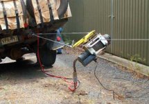
I added an "extension cable" and attach the winch to the vehicle (any where) via a synthetic cable. In hindsight it can be a single cable if secured to the winch cradle appropriately.
This means that the winch always points directly to the point it is winching from and the cable is always square to the winch drum and it always lays up on the drum perfectly.
I can also pull in any direction and theoretically use the winch to put the vehicle back onto its feet if it fell over,

07-10-19 to 23 009Ec.jpg
Cheers,
Peter
OKA196 motorhome
 

retiredblue

New member
WOW Peter I've never seen THIS before- looks scary- but looks like it's something you've done- and successfully- nice job mate. Yeah I'm starting to think that this project is getting way to complicated and expensive (cable is crazy expensive here) so I may just mount the winc in the front on 'when needed" basis/mount. Thanks for the formula.
 

Peter_n_Margaret

Adventurer
I find that the most use the winch gets is to rescue other vehicles. In this case the mounted position of the winch is of no concern because you can position your vehicle wherever it suits.

The second most common use is when you have driven somewhere that you should not have driven. In this case you almost always need to winch yourself out BACKWARDS.

I can plug the winch power lead into the crank battery at the front or into the larger house batteries at the rear. Both sets of batteries can be connected together to help each other out.
My winch rides up front in a Hayman Rheece style hitch when not in use and can be mounted in the rear in a similar hitch/tow hitch, but it could just as easily be carried unconnected in a storage box somewhere.
Cheers,
Peter
OKA196 motorhome
 

DaveInDenver

Middle Income Semi-Redneck
ok I have 2/0 I can lay my hands on I'm just wondering how difficult it will be to hook to the battery lug itself
BTW this winch maxes out (according to the techs) at about 330 Amps at full pull
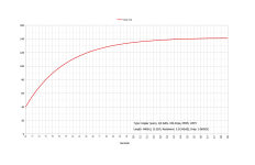
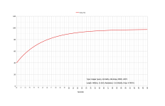
Re-ran 2/0 AWG, 105°C EPDM at 330A and 248A (75%) and full loop length for voltage drop.

Disclaimer: do your own research and draw your own conclusions, this is not professional advice!
00awg-480in-330amps.png

00awg-480in-248amps.png
 

mog

Kodiak Buckaroo
I did this with my 16.5ti Warn.

View attachment 849710
Note to self - Don't mess with Peter who uses a 62.5 kg (138 lbs for the 'tiny' portion of the world that uses the imperial system of measurement) winch, as a 'portable' winch. :oops:
Dang, I have a hard time moving mine without cable/rope around the garage. I am impressed. Who knew Vegemite was a performance enhancer
 

broncobowsher

Adventurer
The temp rise tables are flawed. It is assuming that there will be a 12.5V drop in the wire. I'll dumb the math a little, 10V at 400A is 4000 watts of energy. That sounds correct for the heat rise calculations. But you are not dropping 12V (or my dumbed down 10V) across the wire. You are dropping 1V, and only at full load. So that 4kw heating element of copper wire is now only 400W of heating element. And there is a lot of thermal mass and a lot of surface area to dissipate that heat. It will get slightly warm. But the winch will burn out or the battery will be dead well before the power lead is anywhere near overheated.
 

1stDeuce

Explorer
Just as I was going to toss the BS flag on the field, Broncobowsher sets it straight...

I suggest using welding wire for the run as it's pure copper and has a nice tough jacket. According to charts on the internet, 1/0 is good for 350A, 2/0 should handle 400. I've used 1/0 on most of my installs with no issues. With two batteries, 1/0 will even work for a larger winch, but with only one battery, I'd recommend 2/0 so your winch sees a bit more voltage at max draw. Neither will overheat and smoke in 4 seconds, or even 4 minutes...

Note that you only need one full length wire run, for the positive. Unless you're wiring a really short vehicle, or the battery is in the middle, 20' is probably not enough... I lay an extension cord along the route, mark it with tape, and then remove and measure to get a length, as it's never a straight run once you start trying to strap it under the vehicle...

I also use the frame for ground return instead of running a full length ground wire. The frame is a MUCH better conductor than the wire, and it's FREE. I run a short ground wire from the Anderson to the frame, and then another from the frame to the battery. A heavy wire from the frame to battery is VERY IMPORTANT because the factory ground path from frame to battery was never intended to handle 400A, at least not in a continuous application like winching!

You might also consider putting a shut off switch on the positive leg of your winch wiring, right at the battery. This keeps the wire under the truck from being hot all the time, which can lead to corrosion, particularly if your are from an area where they salt the roads in winter. It also keeps it from burning down your truck if something happens on the trail. If you turn it on to winch and it's shorted, you'll know right away and can shut it off before (too much) bad stuff happens...
 
Last edited:
  • Love
Reactions: mog

1stDeuce

Explorer
FWIW, a 13,000lb winch (??) as a "portable" winch might be a bit much... Even my "little" 9000lb Warn on a multi-mount was pretty heavy... I suppose synthetic cable drops a bit of weight, but it would be my opinion that you do not need or want a 13,000lb winch for a portable recovery winch unless you're built like The Rock, or Peter evidently... :)
 

TwinStick

Explorer
I absolutely agree on the winch being used way more to pull yourself back out of what ever you got into, rather than the front.

We had a 08' Power Wagon and the entire electrical system for the winch was way under sized. I think that they actually remied the system on the newer ones and at one point they offered a dual alternator option and 420 amps of power and I think they upgraded the cable size accordingly. Haven't checked since I traded it in.
 

DaveInDenver

Middle Income Semi-Redneck
The temp rise tables are flawed. It is assuming that there will be a 12.5V drop in the wire. I'll dumb the math a little, 10V at 400A is 4000 watts of energy. That sounds correct for the heat rise calculations. But you are not dropping 12V (or my dumbed down 10V) across the wire. You are dropping 1V, and only at full load. So that 4kw heating element of copper wire is now only 400W of heating element. And there is a lot of thermal mass and a lot of surface area to dissipate that heat. It will get slightly warm. But the winch will burn out or the battery will be dead well before the power lead is anywhere near overheated.
The voltage drop is calculated but for heating it's not used. The 12.5V in the chart indicates the forcing voltage I assumed. I could put it at 10V or 14V. It doesn't matter for the temp rise. I include it only as reference so I can calculate a percent drop.

In fact the simplified MIL-W-5088 for temp rise requires only current and constant "K" per wire gauge that was I believe found originally empirically and given there in a chart for allowable conductor current. I just derived this constant and put into a spreadsheet for myself so I could reverse the calculation. This method would though have to presume teflon insulation at specific wall thickess to be completely valid. Most ampacity recommendations seem a variation of this techique and found experimentally with a particular margin of safety added (NEC is very conservative for example).

So for the purposes of the charts I've derived a formula that relates current, time, resistance, mass (e.g. based on diameter or thickness) and specific heat. It's essentially an expansion of the standard exponential heating formula. I have reasonably precise material data for EPDM, PVC, XLPE insulation for use on insulated or bare copper and aluminum. For SXL/TXL/GXL I have a best guess thermal resistance value.

A conductor's temperature (and therefore relatedly the current carrying capacity) isn't just simply that of copper. The jacket insulates and keeps heat in so it will run significantly warmer than bare wire. Heat is conducted through (or resisted by, depending on your perspective) the insulation and dissipated into air. It's not simple to do analytically and I do not claim what I've done is absolutely accurate. I am most definitely not a thermodynamics professor, just a practicing engineer. Electrical at that, not even a mechanical or chemical to really understand the physics. I treat this topic as I would any heat sink calculation, a heat source with a combination of basically ideal materials and interfaces (thus given or calculated thermal resistances) until I reach free air.

If you and @1stDeuce want to discuss this in more detail (I don't want to put my work into the public domain) I'm happy to talk about better ways to calculate this but I have closed the loop casually on a few final designs, the method worked for my purposes so I just offered it for what's it worth since it allows flexibility in selecting wire size and insulation type instead of the options canned tables allow and will have no derating included. The value is what it is, the designer can choose the margin. The most significant weakness I can see in what I've done is that it does not factor for surface area or skin. I toyed with that but that seemed to really steer into the weeds without adding to the usefulness of the tool. Assuming the conductor and insulation are homogeneous lumps seemed to work well enough for the task.
 
Last edited:

Peter_n_Margaret

Adventurer
VOTLAGE DROP =
[cable length (in metres) X current (in amps) X 0.0164] divided by cable cross-section in mm.sq.

Cable length includes both positive and negative cable lengths combined.
Cheers,
Peter
OKA196 motorhome
 

Forum statistics

Threads
188,009
Messages
2,901,105
Members
229,355
Latest member
BDM66
Top