2AWG would be WAY overkill for the Panel->Controller connection.
Your 160W panel will push nominally 10A or less. The ampacity for 10AWG wire is 30-40A, depending on conductor type and construction. For that short of a run, you could theoretically do 14 or 16 AWG (but the 10 AWG you have is excellent)
As others have said, the controller->battery connection is more critical, and those two should be located near each other (respecting all installation guidelines regarding mounting positions, etc.)
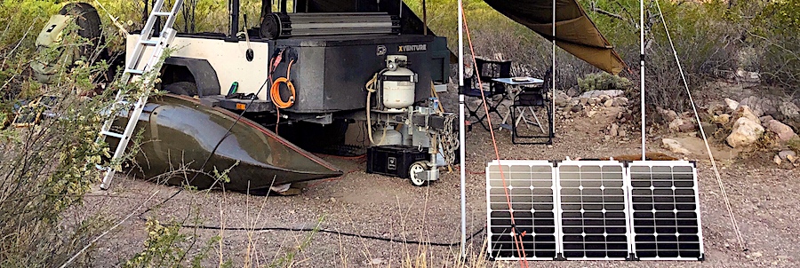
Similar to the OP, I have a 160 watt panel, Renogy Viewstar 20A PWM controller, and a 100AH AGM battery, except about 18 feet of wire from solar panel to the Renogy controller.
#16 AWG TFF or MTW wire for the 18 feet run to the solar controller. Horrors! That allowed me to run the wire underneath a door and gasket, without any roof holes/penetrations.
It was a simple experiment on wire size. Although helpful, you don't have to totally rely upon wire rating charts. Hook it all up close together before installation, draw the battery down, and be prepared to read voltages with a meter when the solar panel current reaches about 10 amps.
Another horror! I void solar panel warranties by cutting off MC4 connectors and replacing them with Andersons, as they allow you to place a voltmeter lead into them for reading voltage and an MC4 doesn't. I've also had MC4 connectors overheat.
With the experimental wad hooked up, when solar current reaches ten/max amps, place one voltmeter lead in the solar panel's + lead, and the other voltmeter lead in the solar controller's + lead, and read DC volts. Hopefully, tenths of a volt loss along one wire. Multiply the tenths of volts times the the ten amps for wattage/heat loss on that one wire. Measure the other wire, should be identical. Add the two together for total wire losses. About 8 watts for me, and that diminishes as the batteries charge and solar current goes down.
I have two twelve feet long, very small gauge telephone wire test leads to allow testing points 24 feet apart. Any time solar charge current/amps seems too small, I test individual wires from panel to charge controller. It has been difficult to prevent occasional termination power losses. From having a number of monitoring devices and connectors, I have removed numerous wondergadgets to simplify for easier maintenance.
The same test for each wire from the solar controller to the battery is helpful, as well as from the battery, to each load. Those small voltage drops are power killers. Performing the same test on one wire end-to-end from battery to load will also show voltage drops/power losses to that load. A compressor fridge will get your attention at start up.
Those long, really small test leads, are my favorite electrical testers for solar. Start at the source (solar panel), then test point to point.
My first solar was a Renogy suitcase with the controller on the solar panel. Those individual wire voltage drops/power losses caused that controller to wind up near the battery.
No arguments with bigger is better, but if that larger than necessary wire has connections becoming corroded or numerous non-perfect connections/resistances unnoticed, you then have smaller wire. An infrared thermometer looking for heat at connections is handy.


