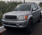
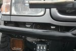
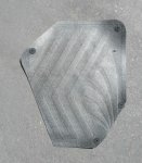
2002 Sequoia Limited 4WD

Sal R.

Active member
MODIFICATION: Auxilary Lighting

GOAL:
Improve nighttime visibility.

PURPOSE:
A recent trip up the mountain in the dark to stargaze and watch the meteor shower had me rethinking my lighting. The trail I frequent was easy enough during the day, but at night, it got a little hairy trying to navigate thru the switchback with just the OEM lighting. I was going to wait until I had a front bumper, but that's going to be awhile, I think.

Despite the fact that I don't really wheel at night, this might not be the last time I take the opportunity to star gaze, either.

Coupled with the fact that winter is just around the corner, I thought that this might be the time to add some low level aux lighting for night trips and snow.

MATERIALS:
Rigid Industries 10" SR2 Hyperspot/Driving Combo Light
Rigid Industries D2 Dually Amber Driving Light
Relay and misc wiring

DURATION: 1 hour

COST: $550

HOW-TO:
I settled on the 10" Rigid Industries SR2 driving/hyperspot combo and the D2 Amber driving light for snow and dusty conditions. I didn't do the whole length of the bumper opening just because I wanted my light choices to be usable on my future bumper.

Removing the bumper skin is pretty simple.
  1. Remove some M6 bolts hidden under the fender liner on the DS/PS and under the bumper holding the fender liners.
  2. Remove misc push clips above and below bumper.
  3. Disconnect the fog lights (if you have them).
  4. Bumper just slides off.
They are wired independently so I can utilize them however they are needed. I added the lights onto my existing electrical framework (see previous posts) each on individual relays.

IMG_20170816_190250.jpg

Still looking at ditch lights solutions. I hear Rago Fab is doing cool stuff for the 1st gen Tundras...
 
Last edited:

Sal R.

Active member
After playing around with different tire deflators, I settled on the J.T. Brooks Pro tire deflators. Having tried the EZdeflators and Staun tire deflators, JTB was the easiest to work with. The best part is that they can be adjusted without the need of a compressor and a spare to set the pressure. This gave you the ability to set it on-the-fly depending on the conditions.

The process is simple, loosen lock ring, turn body to adjust psi setting (15psi), lock, & done.

I've deflated over half a dozen times and the deflation result was always 15-16psi. Contrast that to EZ and Staun, where the setting was good only the first few of times, then it needed to be set up again because it would miss its target psi. The Staun performed better than the EZ. Time-wise, it takes about 5-6 minutes. In that time, I can remove my swaybar links and be trail ready in under 15mins, less than half the time it used to take me, which includes removing the deflators and packing up the links and associated tools.

You get what you pay for...

IMG_20170816_193526.jpg
 

Sal R.

Active member
MODIFICATION: Auxilary Lighting (Round 2)

GOAL:
Improve nighttime visibility.

PURPOSE:
Add supplementary lights to the rear when backing up. Even with the IR reverse camera, things can be difficult to see. Let's face it, for $10, it's not that great a camera.

MATERIALS:
nilight LED Flood Lights
Relay and misc wiring

DURATION: 1 hour

COST: $30

HOW-TO:
To finish up this round of aux lighting, I added some cheapy nilight LED flood lights to supplement the rear lighting. I couldn't justify spending $$$ for something that is only utilized when I'm backing up.
lights21.JPG

This pair had the right dimensions that would enble it to fit in the empty recess of the OEM bumper reinforcement w/o having to cut metal. Cut a hole on the bumper cover and install.

AFTERTHOUGHT: In hindsight, I wish I spaced them outboard out a little more. They are bright, but too much of the dispersed light is throw center and washes out the camera image.
lights22.JPG

I thought about enabling them when I was set to reverse, but instead, I settled on an independent switch so I could utilize them whenever needed.

For power, it is wired into my existing electrical framework.

AFTERAFTERTHOUGHT: In hindsight, I wish I'd gone with something better. These lights don't do ******** in whiteout snowy conditions.
 
Last edited:
Sal R.

Active member
MODIFICATION: Auxilary Light Switches

GOAL:
Aesthetically add switches for the auxilary lighting.

PURPOSE:
Real estate for switches is a premium in the Sequoia and I didn't want to spend premium $$$ for systems like SPOD or SwitchPros. It was too much money for what they were.

MATERIALS:
3/4" SPST Illuminated Mini Rocker Switch
OEM Tundra Fog Light Switch PN: 84160-0C010
Misc Wiring

DURATION: 2 hours

COST: $40

HOW-TO:
I put the auxilary lighting (light bar and rear lighting) on the simple illuminated switches and put the Rigid Amber D2 fog lights on OEM fog light switch from an 00-01 Tundra (PN: 84160-0C010). Picked up the switch on eBay for $30.

For the rocker switches, I mounted them on the blank next to the dimmer knob grouped together. I did have the grind down the housing 1/16" on the sides so that it would fit inside the blank plate. The switches are then glued together using two-part epoxy. I was real careful not to use too much so that it didn't jam the rocker operation of the switch.

The middle switch is blank for future growth. Maybe I'll use it for alley lights or something.

IMG_20170920_133944.jpg

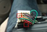
Additionally, below are the details of the OEM fog light switch pinouts:

IMG_20170920_134005.jpg

Green: Illumination +12V
Green/Red: Signal +12V (to fog light relay)
White/Green: Ground
Yellow/Red: Source +12V

The switch creates an on/off circuit between the Green/Red & Yellow/Red lines.

The panel they are mounted on is simply clipped in. However, you have to remove the lower knee bolster to remove the panel. It just pops right out.
 

Sal R.

Active member
MODIFICATION: Rock Sliders

GOAL:
Prevent more damage to the rocker panels.

PURPOSE:
Pretty self explanatory here. I've got a few scraps and minor dents on my rocker panels. Eventually, my luck is gonna run out.

MATERIALS:
Stubbs Welding Ultimate SKO Rock Sliders

DURATION: 2.5 hours

COST: $800 with Installation

SYNOPSIS:
Had a local shop weld the slider on. They even painted it gloss black. I decided on the Ultimate simply because I wanted something different that everyone else. Yes, the HD-SKO is tried and true, but the Ultimate SKO were just calling out to me. And I'm glad I did it. They look fantastic.

These sliders are beefy weighing in at 92 lbs total. I definitely feel it in the skinny pedal. Even w/ 4.56s, there is a bit of drag due to the additional weight.

The package came w/ sliders and scab plates only. No gussets. Based on everything I've read, it should be okay. Just looking the frame sub structure (from an engineering standpoint), it's high likely the frame will deform before the slider give way. Frame metal is thiiiiiiin....
IMG_20171010_140707.jpg

IMG_20171010_140650.jpg

IMG_20171010_160343.jpg

The kickout sticks out about 1" past the tire.
IMG_20171010_154033826_HDR.jpg

IMG_20171010_154345654.jpg
 
Last edited:

Sal R.

Active member
MODIFICATION: Maxtrax II Mounting Brackets

GOAL:
Mount the traction boards securely and unobtrusively.

PURPOSE:
Custom roof rack requires custom brackets. I didn't want those dirty ass things inside my cab, as well. Additionally, I didn't want to pay $50 for something like Rhino Rack's offering on top of the cost of the Maxtrax mounting pins. And, it had to be loooooooow profile. That's a lot of requirements.

MATERIALS:
Maxtrax Mounting Pins
Aluminum strap 1.5"x48"
M4x0.7 bolts x16
80/20, Inc. 10-series T-nuts

DURATION: 2 hours

COST: $45

HOW-TO:
Thanks to my rack design, making custom brackets is easy, but it did take some math.

Some notes:
Required Rack Length: 31-7/8"
Maxtrax Inboard Pin-to-Pin Length: 34-15/16"
Pin base diameter: 1"
Mounting pin diameter: 5/8"
Crossbar length: 2"

To make all the brackets the same dimensions, the measurements above yielded a bracket length ~6" long.

Nothing to it really:
  1. Cut metal strap ~6" long.
  2. Drill mounting pin hole using drill press
  3. Drill crossbar mounting hole using drill press
  4. Paint and clear coat.
But before I go thru the trouble of shaping and finishing metal, a proof of concept (using scraps) would be nice to make sure the intended design works out.
IMG_20171010_154227092_HDR.jpg

IMG_20171009_174705124.jpg

It fits! And nice and low too!
IMG_20171010_154106204.jpg

With the concept working, I shaped and finished the following brackets:
IMG_20171019_114259.jpg

IMG_20171019_114354.jpg
 
Last edited:
Sal R.

Active member
MODIFICATION: Auxilary Lighting (Round 3)

GOAL:

Improve nighttime visibility.

PURPOSE:
Shoot some more light to the L/R.

MATERIALS:
Rago Fabrication Tundra Ditch Light Brackets
Rigid Industries Dually Flood Lights

DURATION: 1 hour

COST: $200

HOW-TO:
I ordered this ditch light kit thru Rago fab "Blacktober" sale. The brackets do come instructions about installation and their site even has YouTube vids for reference. All in all, it was very straighforward.

To summarize, the brackets mount to the hood and has plenty of clearance from the cowling and windshield when open. I wired the pods in-line with the front lightbar on an indiviual relay. I set it up so that the pods can easily be disconnected and removed when it is not being used. I don't really need them on all the time and, personally, I find them obnoxious daily driving.

Personal note: Having these lights shine on my hood just reinforced the notion of staying away from roof-mounted light bars/pods. Even with just these pods, the light off the hood was annoying.
IMG_20171019_114501.jpg

IMG_20171019_114539.jpg

You do have to trim the cowling (and this is noted in the instructions) and below is the end result. I got lazy and trimmed the cowling (using a knife and dremmel tool) while it was on the vehicle. You can't even see it anyway...
IMG_20171019_114623.jpg

2017-11-02 07_50_41.jpg

UPDATE: I pulled these off and moved the floods to the bumper. The light shining off the hood was irritating.
 
Last edited:
Sal R.

Active member
MODIFICATION: Barrier Net

GOAL:
Create a barrier as a precaution for wayward projectiles coming from the rear.

PURPOSE:
Despite the fact that I, generally, go out exploring alone, I do carry a reasonable amount of recovery gear just in case. As a result, I've been very concerned about all the things that can go wrong during a recovery operation. Broken whatever flying through the air. It forced me to take a good, hard look at improving driver/passenger safety and survivability. After reading about a guy killed by a broken shackle flying from the rear, I knew I needed a barrier net, but none exist for the Sequoia...

MATERIALS:
Truck tailgate net (17" x 54") working 3k lbf/breaking 6k lbf
Cam buckle straps (qty. 4)
Grommets
D-Ring anchors (Qty. 2)

DURATION: 2 hours

COST: $40

HOW-TO:
Because of the way the 2nd row seats fold, the left over opening above the folded seats, coincidentally, aligns with a typical truck tailgate dimension. I figured if a tailgate net is strong enough to take the load of whatever, it certainly will do the job as a barrier. Looking over the dimensions and material of a tailgate net and comparing it to more expensive units offered up by companies such as Raingler, I'm confident that it'll work. The nylon straps and opening are similar, as well.

Starting with the truck net, I added steel grommets on all for corners that would serve as the tie-down points, while the cam buckle straps would ensure the barrier stays taught. The upper mounts to the grab handles .
IMG_20171105_125601120.jpg

The lower mounts attach to D-rings I added to the seat rails.
IMG_20171105_125609542.jpg

I notched the trim pieces to keep an "OEM" look about it.
IMG_20171105_143524978.jpg

With the seats folded up and net in place, it provides better protection than just open space. I can even hang gear on it, if needed. Additional storage is a added benefit.
IMG_20171105_125244555.jpg
 
Last edited:

Sal R.

Active member
MODIFICATION: Ambient Lighting

GOAL:
Improve in-cab nighttime visibility.

PURPOSE:
One of the features I really miss from my old Audi A4 was the factory overhead ambient lighting. It was an illumination method that allowed me to see the center console at night without having to turn on the map lights and ruin my night vision.

MATERIALS:
Oznium 6mm Red LED

DURATION: 20min.

COST: $10

HOW-TO:
There was a spot perfect for the addition of the LED.
IMG_20171107_154407909.jpg

Installation was as simple:
1 - Removing the overhead console
2 - Drill a hole for the LED
3 - Tapping wiring for power/ground
4 - Re-install

To remove the overhead console, open the sunglass holder, remove the pictured screws, and pull down gently. After the screws are removed, it's held in by clips.
IMG_20171107_154926889.jpg

Here is where I drilled a hold for the LED. Fortunately enough, the spot I drill had a screw and mount meant to hold the sunroof and homelink controls together. Even without that screw, the tab from the homelink kept the sunroof controls in place w/o the screw.
IMG_20171107_154421557.jpg

For power, I tapped a pink wire (illumination wire) and a black wire for ground.
IMG_20171107_154450121.jpg

Finished.
IMG_20171107_155031280_HDR.jpg

The LED is not flush mounted because it is obnoxiously bright and distracting at night while driving.

The way it's mounted now, it provides nice lighting, but not obtrusive to the the driver and/or passengers.
 
Last edited:

Sal R.

Active member
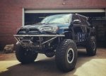
MODIFICATION: Front/Rear Bumpers

GOAL:

Improve approach/departure angles, help protect my investment, and make the rig look more ************.

SUMMARY:
I've never been a fan of plate bumpers. For what I do, plate is overkill, heavy, and bulky. Not saying they don't look good, because some do look sweet (i.e. BruteforceFab), but just not for me. The only tube offering was made by Addicted Offroad for Tundras, but I really wasn't a fan of the lines of that bumper. As with everything else, custom was the way to go. With the new bumpers, the vehicle grew +3", excluding the length of the spare, which, I think, is pretty good.

Requirements:
Front
  • Integrated winch plate
  • Shackle receiver
  • Tabs for light pods/bar
  • Integrated Hi-Lift mount
  • Heavy Duty Skid Plate
  • Minimum Profile
Rear
  • Dual Swingouts for Spare and Jerry Can
  • 2" Hitch receiver
  • CB Mount
  • Minumum Profile
These two rigs served as inspiration for the design I had in mind:

RSO T4R
IMG_20180108_113836.jpg

Dirtco T4R
IMG_20180108_113754.jpg

The reason why I opted to have the Hi-Lift up front was for accessibility and better weight distrubtion front and rear. I figured this will help to keep the center-of-gravity from shifting too far back and keep close to neutral as possible.

With the removal of the OEM bumper, I lost my OEM fogs with it. As a result, I upgraded to Rigid Industries D-Series fog lights. I wired them to the fog light button I added and the D2 driving lights to the factory system using existing factory harnesses.

Integrated into the bumper is a ComeUp Seal Gen2 12.5RS winch with synthetic line mated with a Factor55 Flat link for extra badassery.

IMG_20180108_110154.jpg

The reason for dual swing outs is simply because I did not want a 50+" swing arm sticking out while in the open position. I wanted to keep the install tight. This rig a daily driver and will see tight stalls at a mall or shopping center. I would have preferred to pass on the swing outs, but the spare doesn't fit in the OEM location, would have hung down way too low, and I didn't want to sacrifice my cargo space to house the spare inside the cab. No way I'm going throw a 100lb spare to/from the roof. Since I have one arm already, I thought, "why not make use of another arm?" In hindsight, I wish I'd gone with a three-can holder. One can is not enough for long excursions and there is just enough room for three while sacrificing additional 2" on the rear profile.

IMG_20180118_214501.jpg
IMG_20180108_120128.jpg
 

Sal R.

Active member
MODIFICATION: Plano Case Rooftop Storage

GOAL:
Moar storage!

PURPOSE:
Add a low profile, easy-to-access storage, mainly for recovery gear.

MATERIALS:
Plano All Weather Tactical Gun Case - 36"
Thule Rack Mounting Kit

DURATION: 30min.

COST: $55

HOW-TO:
Amazon had a Plano gun case I had saved on "sale" so I thought, why not? It was a nice low-profile, tried-and-true storage solution.

In my last trip out to the desert, I got stuck. And I learned that opening the swingouts, then hatch, then crawling into the cab to haul out the recovery gear, then close everything up was a pain. Plus it dawned on me that I could get into a situation where opening the swing outs and hatch could prove difficult/impossible.

So, up on the roof they go next to the Maxtrax.

To mount it "cleanly" and securely, I used some left over Thule mounting feet from a snowboard rack I modified to secure it onto the rack. Drilled holes, passed the M6x1.0 bolts through, tighten, and done.

The same mounting hardware can be purchased through etrailer.com.
IMG_20180116_103222.jpg

IMG_20180116_103157.jpg
 
Last edited:

Sal R.

Active member
MODIFICATION: Uniden Dash Cam

GOAL:
Add extra insurance and some undeniable accountability.

PURPOSE:
Having an impartial witness to bad driver shenanigans is always a plus. Seeing that a 2.2K mile road trip was on the horizon, having some extra insurance was not a bad thing.

MATERIALS:
Uniden DCAM Dash Cam
iSaddle Adhesive Windshield Cam Mount
AUTO-VOX Hardwire Kit with Mini-Fuse Adaptor

DURATION: 30min.

COST: $60

HOW-TO:
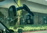
Picked up the DCAM on a black friday sale online. The hardwire kit is run tucked into the roofline down the a-pillar and the inline fuse is jammed into the power outlet fuse.

So far, it's a great little camera. It's configured to automatically turn on and start recording on ignition accessories on and automatically shuts down on ignition off.

It did not fail to record during my 2.2k mile road trip. The resolution is not that great, but it does the job of capturing traffic. Has a fairly wide FOV and captured everything in front of me.

I did have to modify the ball mount to add some extra adjustbility so that the camera wasn't angled downward relative to its position on the windshield.
IMG_20180115_140831.jpg

IMG_20180108_124734.jpg
 
Last edited:

Sal R.

Active member
MODIFICATION: Relay Bus Version 2

GOAL:
Add more accessories and keep the wiring clean.

PURPOSE:
The addition of lighting quickly turned my wiring paradise to a collection of spagetti crap that my anal retentive nature just could not accept. Adding new circuits was easy, in theory, but the actuality of it was a pain. A revision was needed.

DURATION: <3 hours

MATERIALS:
HELLA H84988011 7-Way Mini Relay Box Kit (qty. 2)
5-Pin Mini relays (qty. 10)
Misc 12, 6, 4-pin connectors

COST: ~$120

HOW-TO:
I paid a premium and opted to use two 7-relay mini relay buses since space is a premium and I wanted to keep the install tight.

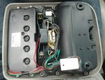
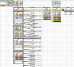
Before diving into it, I planned ahead and put together a pin out diagram:
IMG_20180206_135826.jpg

The idea was to make adding new circuits stupid easy and the relay buses removable for troubleshooting and maintenance, hence the need for multiple connectors. The new wiring schema would be conducive to future growth.

Wire grouping for each specific connector was determined by the direction a specific wire was going to be routed.

The end result of the newly implemented electrical framework is that all my existing accessories are collected in one spot using a total of 10 of 14 relay positions, as opposed to, the original 5 relays in the old bus holder and the rest made to fit everywhere on the vehicle. Additionally, I built in a total of 7 available pre-wired slots for new accessories inside the cab (3 independent & 4 switched with relays). This gives me the option of adding alley lights, rock lights, HAM, etc. with ease.

IMG_20180206_135742.jpg

The process is:
  • Add switch (somewhere)
  • Plug in relay
  • Add accessory to appropriate pin out on connector
  • Ground accessory
  • Add fuse
  • Gravy
 
Last edited:

Sal R.

Active member
MODIFICATION: Power Steering Cooler & Air Hose Remote Quickdisconnect

Knocked out a couple things.

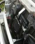
New Derale 13212 power steering cooler picked up from Amazon. It is plumbed to replace the OEM "U" shaped steel line "cooler." My hoses are super leaky and it's time to stamp these out before the summit.

A few SAS'ed taco guys use this cooler and the price was right ($40) compared to more expensive units like B&M ($90). Hey, if it's good enough for SAS'ed tacos on 35s and 37s, it's good enough for me.

IMG_20180402_130030.jpg

Had to shape some brackets with some spacers, but it was no big deal. Clearances get a little tight under the upper portion of the grille, but I have about 1/2" to spare. The new cooler is spaced off about 1/2" from the oil cooler.

Mocked up:
IMG_20180402_130017.jpg

Painted, plumbed, and installed:
IMG_20180406_180158.jpg

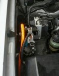
Next up was a remote fitting for the air compressor air hose. It got annoying to have to pop the hood during snow or rain to gain access to the air compressor to air up. It is fitted where my windshield reservoir used to be located.

I used some cheapy air lines from Harbor Freight cut to length with some 1/4" NPT standard fittings with a barb fitting at the end. Teflon tape applied where applicable. So far, so good. No air leaks and works as it should.

On the downside, the ARB air hose kit I purchased for airing up is leaking air at the compressor-side fitting.

What a let down...

IMG_20180403_123506.jpg

IMG_20180402_130003.jpg
 

Sal R.

Active member
MODIFICATION: Rear Diff Breather & Cover

Finally got around to doing the read diff breather mod. Muddy water crossings this winter really made me prioritize this modification.

Used union fitting Toyota part number 90404-51319. Picked up on Amazon and coupled it with some left over power steering reinforced rubber hose from the power steering cooler mod and I routed it along the gas filler tube up to the gas cap.

Check off one more item for summit prep.

Note: Gettin' muddy is overrated...

With the completion of the rear diff breather mod, needed to do something about some exposed lines.

The removal and replacement of the rear bumper left my gas and vent lines exposed to debris kicked up by the tire.

If I hadn't sold my bumpers, I would've probably salvaged it off the rear bumper. Oh well.
IMG_20180408_124757.jpg

With some left over rubber mats cut to shape, came up with this cheap simple cover. Time will tell if this holds up in this location. Worked out great up front, so far.
IMG_20180408_124838.jpg

IMG_20180408_124916.jpgIMG_20180408_124916.jpg

One more thing checked off for summit prep.

IMG_20180408_125142.jpg
 
Last edited:
Forum statistics

Threads
188,334
Messages
2,905,569
Members
229,959
Latest member
bdpkauai
Top