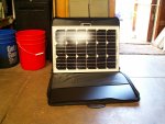
35 watt solar blvd panel

pods8

Explorer
I was surprised that on the solarblvd website it listed the 25 W panels at 9 lbs each. This was wrong. I weighed my panels with a certified scale and they are 4.84 lbs. each. My frames are not double walled though, much thinner in design.

The shipping charges are off weight, they are pretty accurate on the large ones but seem to sometimes pad the smaller panels. Not sure if on purpose to snag a little more margin or what.
 

bat

Explorer
I was on the fence about the way I did mine and Pods gave me a push in the right direction. I am going with the controller isolated from the panels like you have 4x4 junkie to get the most out of the panels.
 

bat

Explorer
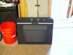
Just picked up a nice storage bag for my panels, it is an art portfolio bag and they fit perfect :wings:

002.jpg003.jpg
 

dwh

Tail-End Charlie
What you really need is the controller at the battery and that the loss prior to the controller when the voltage is higher and going to get chopped down anyways. After the controller it is conditioned to what it needs to be and not much room for losses there.

Not exactly.

Any non-MPPT charge controller / regulator just connects the PV input straight through to the output and then switches it on and off to regulate the battery voltage.

So in regards to voltage drop - it doesn't matter whether the charge controller is near the PV or near the battery - it's all just one big loop with a switch in it.


From what you describe, it sounds like you're thinking of how to set it up with an MPPT charge controller.
 

pods8

Explorer
Not exactly.

Any non-MPPT charge controller / regulator just connects the PV input straight through to the output and then switches it on and off to regulate the battery voltage.

So in regards to voltage drop - it doesn't matter whether the charge controller is near the PV or near the battery - it's all just one big loop with a switch in it.


From what you describe, it sounds like you're thinking of how to set it up with an MPPT charge controller.

My understanding is PWM is quickly chopping the voltage so that downstream it has effectively created a lowered voltage (usually in the 13.7-14.4 range depending on charge stage and controller) right? Thus if you have a 5% voltage loss after the controller it will only be 95% of the controlled voltage at the battery. If it is a slower switching and its based off what the battery voltage rises to then you're still limited to what the voltage at the controller is (unless there is an axillary battery sensing line) since the controller has no idea how much voltage drop there has been right? Since it is being chopped down any extra voltage that makes it to the controller is just going to get wasted in the PWM chopping so might as well take the loss on that side and let the control set voltage be as accurate as possible at the battery.

That's my thinking/understanding anyways.
 

4x4junkie

Explorer
Agreed, without an external sensing line or sensor, the controller isn't able to monitor the voltage loss on the wiring between the controller and the battery. It's best to have that side as short as possible.
 

bat

Explorer
I found this on Morningstar does it apply here


7. Self-regulate for voltage drops
and temperature effects
With PWM constant voltage charging, the critical
finishing charge will taper per the equation I = Ae-t.
This provides a self-regulating final charge that
follows the general shape of this equation.
As such, external system factors such as voltage
drops in the system wires will not distort the
critical final charging stage. The voltage drop
with tapered charging current will be small
fractions of a volt. In contrast, an on-off
regulator will turn on full current with the full
voltage drop throughout the recharging cycle
(one reason for the very poor charge efficiency
common to on-off regulators
 

dwh

Tail-End Charlie
My understanding is PWM is quickly chopping the voltage so that downstream it has effectively created a lowered voltage (usually in the 13.7-14.4 range depending on charge stage and controller) right?

It's a circuit, or in other words, a loop. So "downstream", the voltage of the loop is going to be whatever the battery voltage is. Which is what the voltage of the "upstream" side will be as well, since with a non-MPPT controller, the upstream and downstream are just one big loop whenever the switch is turned on.

The quick switching on and off of the PWM can limit the voltage of the circuit by throttling the amount of current flowing through the circuit and it can limit the maximum voltage that the circuit rises to.

It can also do a very precise job of holding the circuit at a particular voltage, by switching on and giving a little jolt whenever the voltage of the circuit drops a bit.

But the voltage of the circuit is whatever it is. I.e., whatever the battery voltage is. The charger might *potentially* put out 14.4v, but it won't *actually* put out 14.4v until the circuit (and the battery) gets there. So, until the battery gets to that voltage, there is nothing for the PWM to limit, except the current flow. Once the circuit rises to 14.4v, then the PWM can limit the voltage from going any higher - by limiting the current flow.

"When a battery voltage reaches the regulation
setpoint, the PWM algorithm slowly reduces the
charging current to avoid heating and gassing of
the battery, yet the charging continues to return
the maximum amount of energy to the battery
in the shortest time." [my emphasis added]

http://www.morningstarcorp.com/en/support/library/8. Why PWM1.pdf [Page 1]

And look at Secton 7 (Page 5)

"7. Self-regulate for voltage drops
and temperature effects

With PWM constant voltage charging, the critical
finishing charge will taper per the equation I = Ae-t.
This provides a self-regulating final charge that
follows the general shape of this equation.

As such, external system factors such as voltage
drops
in the system wires will not distort the
critical final charging stage
. The voltage drop
with tapered charging current will be small
fractions of a volt.
In contrast, an on-off
regulator will turn on full current with the full
voltage drop
throughout the recharging cycle
(one reason for the very poor charge efficiency
common to on-off regulators)
." [my emphasis added]


Thus if you have a 5% voltage loss after the controller it will only be 95% of the controlled voltage at the battery.

Well...no. It's a loop. It's not like, "here's one end of the thing and here's the other end". It's all one loop. If you have 5% voltage drop then it'll be a 5% drop over the whole loop (circuit).

And that voltage drop will go away as the battery voltage rises and the PWM throttles back the current to the battery, because voltage drop is a variable based on current flow.


If it is a slower switching and its based off what the battery voltage rises to then you're still limited to what the voltage at the controller is (unless there is an axillary battery sensing line) since the controller has no idea how much voltage drop there has been right?

Yes, correct. But it doesn't matter because the voltage at the controller is going to be the same as the battery, since the battery is setting (limiting) the voltage of the entire circuit. It's not like the controller end is 5% higher than the battery end; there is no "end" - it's a loop.

Now, let's say there's a 5% voltage drop. Well, it doesn't matter, the entire loop will be 5% low until the battery reaches a point where the current flowing through the loop reduces. And at that point, the voltage drop is also reducing. By the time the amp flow gets down to 1a, the voltage drop will down to something like a tenth (or maybe hundredth) of a percent.

Since it is being chopped down any extra voltage that makes it to the controller is just going to get wasted in the PWM chopping so might as well take the loss on that side and let the control set voltage be as accurate as possible at the battery.

Ahh...I think I just found the stumbling block. :)

There is no "extra voltage" (or extra current for that matter). The PV will make power only as long as there is somewhere for it to go. If the PWM were to cut say 50% of the power going to the battery, then the PV will be making 50% less power. The entire loop (PV, controller, battery) will have 50% less current flowing through it.

So, it's not like there is more power on one side of the charge controller than the other - as long as the switch is on, it's just one big loop. And when the switch is off, the whole thing is dead because no power can flow from the battery to the PV due to backfeed diodes blocking it.


Now, an MPPT charge controller is a little different - on the upstream side. It finds the maximum power point to put the most load on the PV and get the most watts out of it. The voltage on the upstream circuit ends up being whatever it has to be to get the most watts. Then it down converts that voltage to whatever it has to be to maximize the amperage, and then feeds that through a PWM to the downstream side, where it acts like any other PWM charge controller.
 

dwh

Tail-End Charlie
D'oh! Beat me to the punchline! That's what I get for taking the time to try and find all my typos. ;D


I found this on Morningstar does it apply here


7. Self-regulate for voltage drops
and temperature effects
With PWM constant voltage charging, the critical
finishing charge will taper per the equation I = Ae-t.
This provides a self-regulating final charge that
follows the general shape of this equation.
As such, external system factors such as voltage
drops in the system wires will not distort the
critical final charging stage. The voltage drop
with tapered charging current will be small
fractions of a volt. In contrast, an on-off
regulator will turn on full current with the full
voltage drop throughout the recharging cycle
(one reason for the very poor charge efficiency
common to on-off regulators
 

dwh

Tail-End Charlie
And to add just a bit more...

Don't trust your multi-meter. :)
Wait, what? Yea, that's right, I said it.


If you measure the voltage at the controller end of the battery side, you'll see a voltage.
But what are you actually measuring?
You are measuring a "short circuit". I.e., from the controller +, through the meter and back to the controller -.
So you are seeing the voltage of THAT little short circuit.
That's NOT the voltage of the battery charging loop.

If you measure at the battery end, what are you measuring?
Again, a short circuit.
From the controller +, through the wire, through the meter, and back through the wire to the controller -.
That is also NOT the voltage of the battery charging loop.

If you want to know what the voltage of the battery charging circuit is, you have to measure in SERIES with the loop, NOT measure a PARALLEL short circuit.
 

dwh

Tail-End Charlie
(Yes, part of that last post was a lie. I'm waiting to see who can call me on it. :D )
 

Forum statistics

Threads
189,927
Messages
2,922,310
Members
233,083
Latest member
Off Road Vagabond
Top