Our last update about two weeks ago had us forging ahead with the various sub projects we were working on. Most of that planned work got set aside as we realized that we were getting ahead of ourselves. We did not go on the planned Easter camping trip due to illness in the family. This was actually a good thing, because there was no way the trailer was going as a result of active work being done.
We started out this period working on installing the new inverter\charger to the lower portion of the wall between the cabin and galley. This would eventually be inside a vented compartment. All of the new wiring was cut to length and the proper ends installed. We were able to successfully test the inverter\charger.

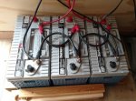
We then started creating a secure way to hold our three heavy AGM batteries in their new permanent location. We know that off-roading can bash things around inside the trailer and we wanted to make sure that the batteries were securely mounted so that they could not move. The idea was to make a tray that would be bolted to the trailer deck. We welded this up using 2”x2”x1/8” angle steel.

It was about the time that we were looking at covering the cabin side of the wall with plywood that we realized we had covered up the steel wall beams for the spare tire carriers. This would make it impossible to mount the carriers with the wall in place. That prompted a quick reassessment of our plans. The carriers needed to be fabricated and installed before we completed the wall work. With that, we tore down everything mounted to it and then unbolted the wall. We drilled the holes to mount the carriers to first and knowing the exact mounting locations drew up some quick sketches.

The plan was to have to side beams bolted to the wall supports and joined between by cross members. We went with this two beam approach after seeing what Gwolff and others went through with creating their carriers. This will provide a very solid base. This base frame has four connectors (two side and two bottom) coming out to a metal plate that the studs are attached to.

All the metal tube is 2”x1” or 1”x1” 1/8“ steel. We welded 1/8" plate across the tops of the side beams to close them in, but left the bottoms open to allow any water that got in there to drain out. The base plate is two 6”x8” and 6”x6” 1/4” steel plates welded together. We would have initially went with a single 3/8” plate, but the shop was out of it the day we went in and did not want to wait for it. We used 3/8” hardware to mount the carriers. The studs are 1/2-20 Grade 8 bolts with the heads tacked to be back side of the steel plates. The fabrication and painting took about four days to complete working mostly nights and part of a weekend.

The tires sit about a 1/2” off the base on the back. This was done so that no rubber touches metal. Here in Arizona hot metal will burn the life out of tire side walls. The base and mounting bolts are all inaccessable behind the mounted tire so the mount can not be removed to take the tire. We will use locking lug nuts to secure the wheels on to the carrier. There is absolutely no movement of the wheel or mount. The mount will hold far more weight than the tire and aluminum wheel. The carriers are not perfect, but overall will meet the need just fine.

While we were waiting between paint coats on the carriers we decided to pull off the fenders and reinstall them with silicon to keep debris from getting between the fender and trailer siding. This was clearly a problem from our last camping trip as seen in the before and after images below. We may add some sort of backing to the fenders to protect the trailer siding sometime down the road. While we were working on the fenders we notice there was some minor damage caused by the trailer suspension bottoming out. As a result, we may move the suspension replacement to the Timbren Silent Ride suspension sooner.


With the carriers mounted we reinstalled the wall. We put in the insulation and covered that entire cabin side of the wall with 1/8” plywood. On top of this we mounted a 3/4” plywood base up the middle for the electrical to mount to. We re-mounted the inverter\charger, solar charge controller and other 12v electrical components. This configuration may change as we need to incorporate a 120v breaker panel some where. This was all moving pretty quickly so no pictures along the way.

We also bolted the battery tray securely to the deck. There is a piece 3/4" plywood inside the tray under the batteries and then the additional 3/4" plywood base underneath the metal tray. All these piece are bolted together to the floor. There is a 2" gap all the way around to insure air flow.

That is all for this update. Next up will be continuation of the 12v and 120v re-installation\installation. We need to get the window, roof vent, water tank and water fill hatch\box installed. We have much of the material and have done some work on these items.
More to come.
Matt


