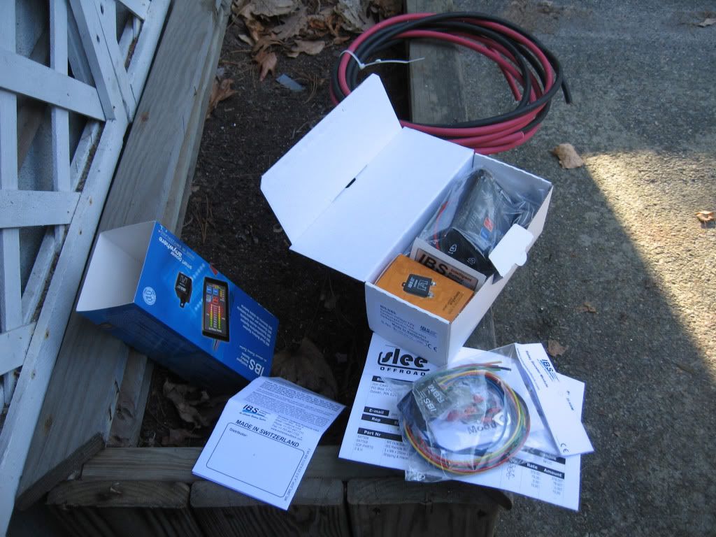
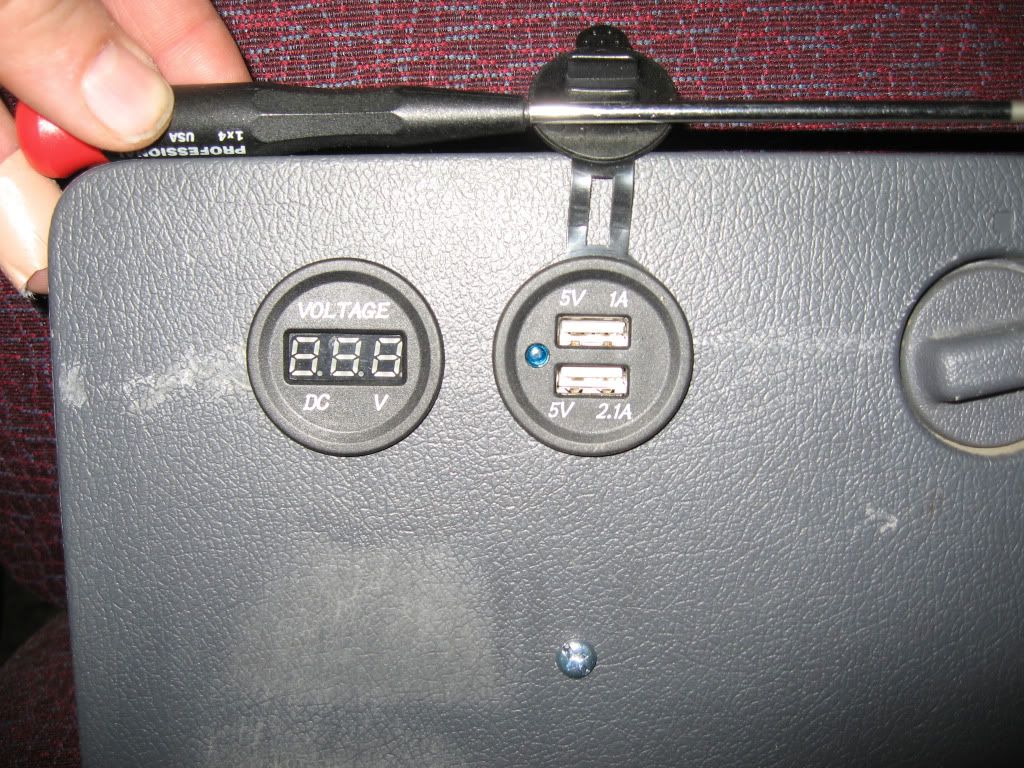
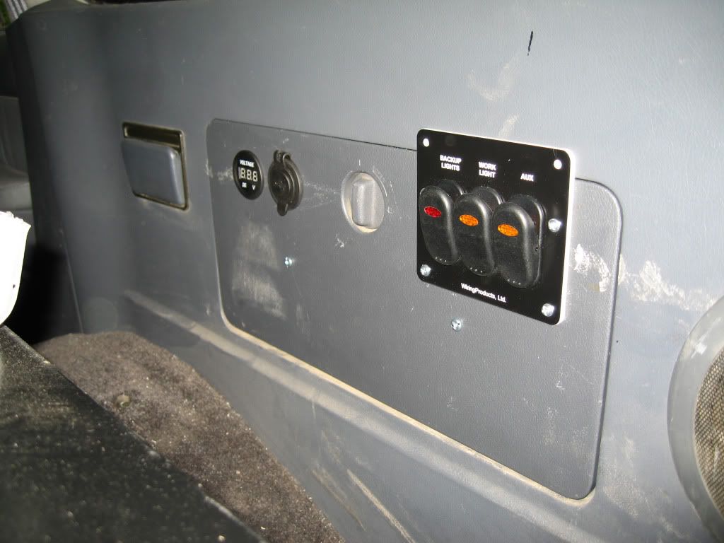
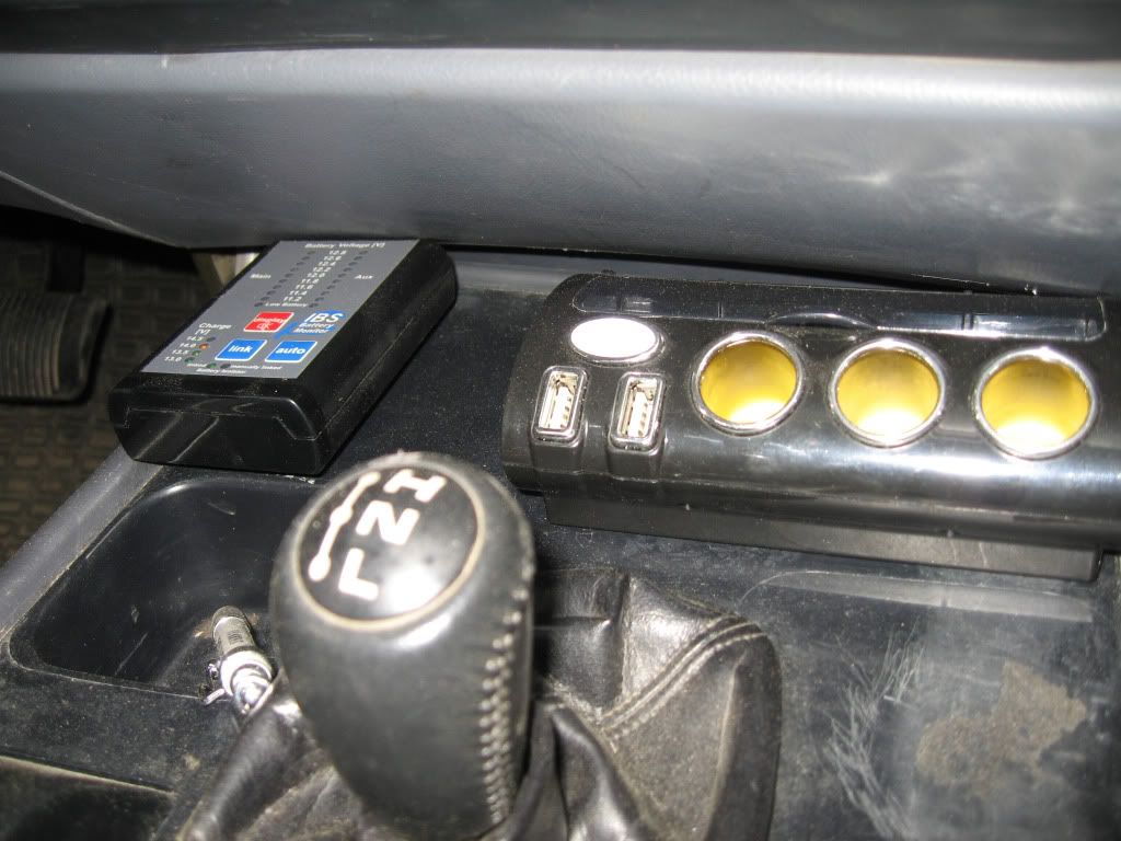
Switch panel with USB charger and voltmeter
All of these goodies needed some switches, and I thought I knew just the place for them. At the rear of the passenger side there is a storage compartment with a hatch cover. I like doing as little surgery as possible to stock body parts, but the hatch cover presented a nice opportunity to drill freely into an easily replaceable part. It also meant I could do the work indoors and drop it in when it was ready.
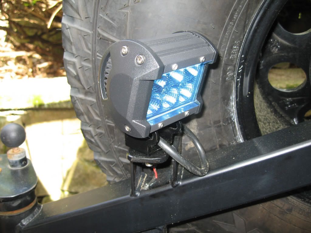
I needed a switch for the work light obviously. I also wanted to be able to activate the reverse lights independently for additional site light. I ordered a USB charging module for gadgets and matching voltmeter so I could keep an eye on the auxiliary battery voltage.
Cruiserheadstore.com
12v Dual USB Socket with Voltmeter - Flush Mount 201 074515613
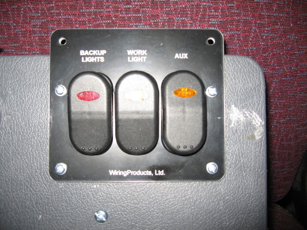
It had become clear by this point that the Baja Bus was an important part of the struggling economy, so I splurged and ordered a three-position switch panel from WiringProducts.com.
Wiring Products.com
3-Position Rocker Switch Panel SP3-001
Switch 1: Surf N Turf Rocker Switch - DPDT ON-ON Red SNT-DPDT-ONON-RED
Switch 2: SPST ON-OFF
Switch 3: SPST ON-OFF
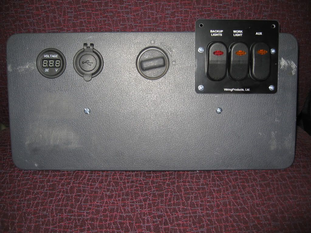
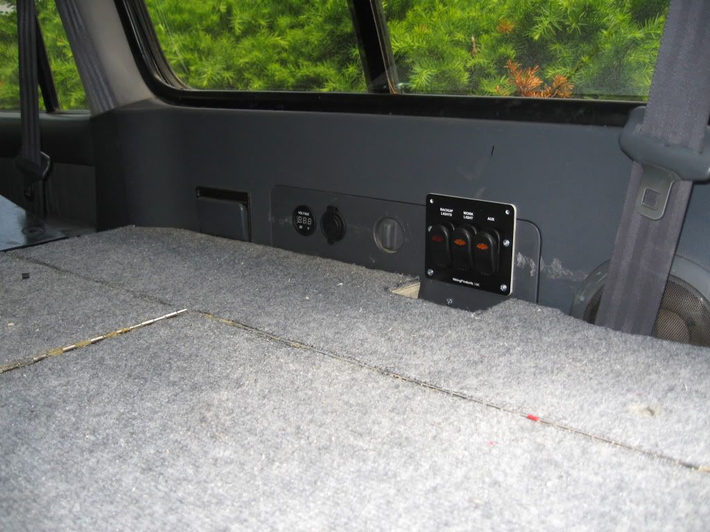
I drilled holes for the voltage meter and USB charger, electing to forgo the black panel they came with. Finally, I cut a single hole for the three switches, since I had the labeled switch panel to cover the gaps. These were placed at the top of the hatch cover on either side of the latch to provide access above the sleeping platform. I didn’t like that the switch panel would extend above the hatch, but decided that was better than tossing it and cutting individual switch holes.
For cosmetic reasons I didn’t want to penetrate the hatch cover more than necessary, so I used some aluminum sheet I had lying around to make a mounting surface for the electronics. Two small bolts secured this to the back of the hatch cover.
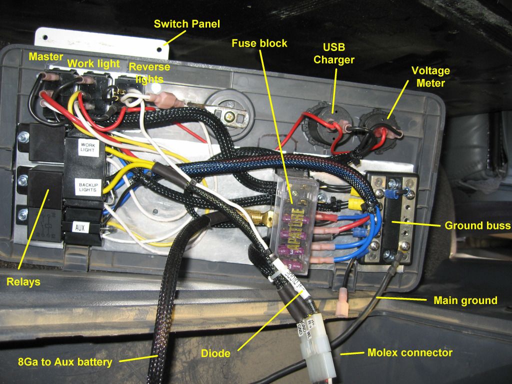
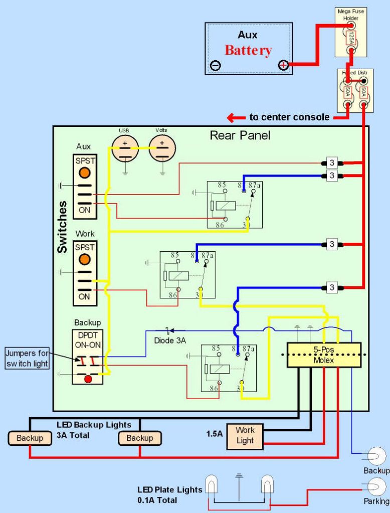
Since I am a ridiculous purist, I decided to use relays instead of wiring directly to the switches, more to gain the experience than from practical necessity. Let me be clear and save the peanut gallery some keystrokes, you DO NOT NEED relays for 18W LED lights, which draw 1.5 Amps each. It is almost criminal overindulgence to do so. I comfort myself with the thought that a) I have no idea what I am doing, and don’t pretend to, and b) at least the relays are there if I ever add something that deserves the added precaution, like a nuclear reactor.
Parts Express International Inc
2 12 VDC 5-PIN RELAY SPDT 30/40A BOSCH TYPE 330-073
1 12 VDC BOSCH TYPE DUAL RELAY SOCKET 330-078
I scrounged up from old parts a six-position fused distribution buss and a ground buss.
As I was putting this together I wondered what I would do with the third switch position, when suddenly inspiration struck. I realized that the voltmeter would always be on, causing a minuscule but unnecessary drain on the auxiliary battery. Also, an accidental bump could activate the lights without me being aware of it, like when I was passed out in the rear after a night around the campfire. Until it had a better use, why not make the third switch a master for the entire panel? This would kill the voltmeter when not in use, and then I would need to accidentally hit
two switches to mistakenly activate lights, instead of just one. I feel so much better.
I added a third relay cannibalized from the Hella fog light kit, and set about making connections.
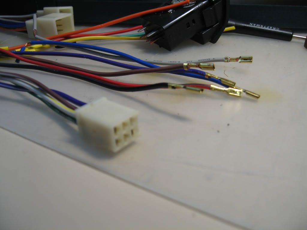
PAY ATTENTION HERE ==> I stumbled on a source for hard-to-find open-barreled connectors, purchasable in small quantities at reasonable cost, that made this work much easier. I read a very convincing article about the benefits of the open barrel design, and was already a Molex and WeatherPack aficionado. Whatever else anybody tells you, a ratcheting crimper is a virtual necessity. I use one with removable jaws. These are called, among other things, "B"-crimp, because the tabs on the pin are made to curve around and close back in from each side on the wire and insulation simultaneously. Get the jaws with three openings that include 12-10 AWG. 'Cuz more is better, right kids? (Actually, the 12-10 position is what allowed me to crimp two wires into one terminal for jumping and extending the same wire across terminals.)
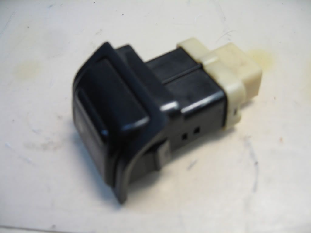
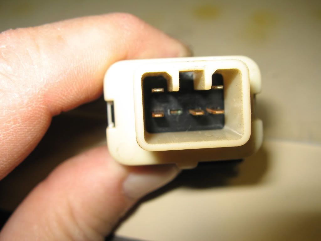
One of the connectors I ordered was the uninsulated ¼” female spade connector that fits the male spade connectors on the backs of the switches. I used shrink tubing (of course...) to insulate most of the connection and provide strength. I also ordered a batch with the little locking tab, allowing me to rewire relay pigtail housings. Finally, I got the .110 version that fit ATO/ATC fuse blades. You never know when they will come in handy. All this was about $15 delivered.
DigiKey Online
25 CONN RECEPT 14-18 AWG FASTON TIN 42238-2
25 CONN RECEPT FAST 14-18 AWG .250 41202
25 CONN RECEPT FAST 18-22AWG .110 42068
The difference between FAST and FASTON is the little locking tab. I forget which is which
")
.
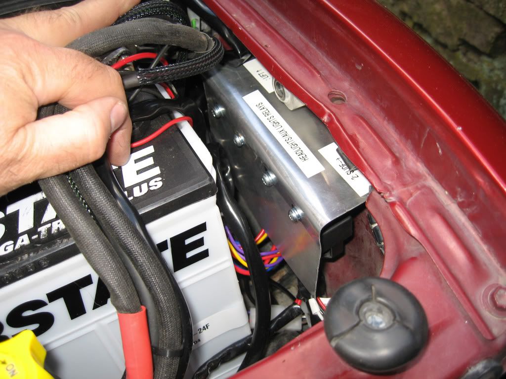
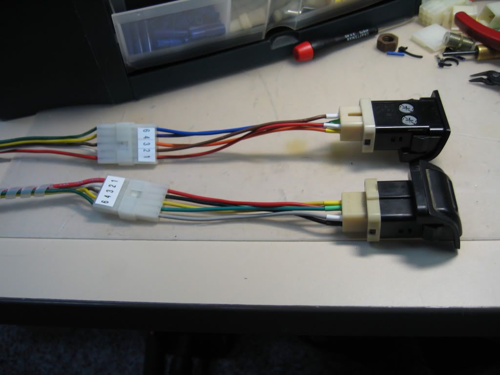
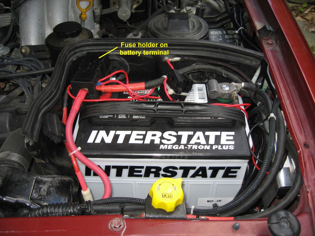
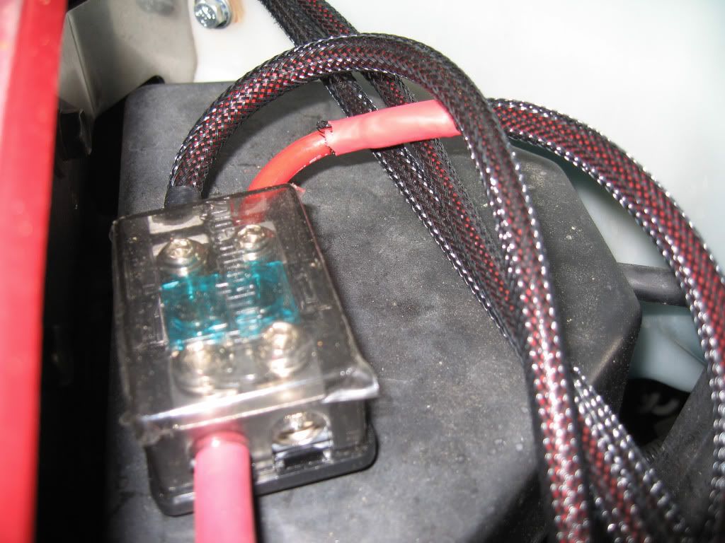
Using these connectors meant I could wire directly from the relay pigtails to the switches with no splices. A bonus came when I realized that they were also used in the “T” connectors in the Slee harnesses. When I added fuses to the headlight harness, I removed the two existing wires going from the T connector to the battery. I crimped one of these connectors onto one end of each fuse holder and inserted it into the T connector. Ring terminals went on the other end of each fuse holder and attached to the battery. Nice and neat, and two more splices avoided in a sensitive area, the main battery tray.
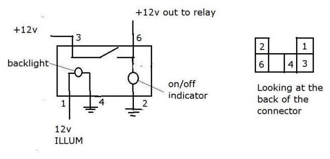
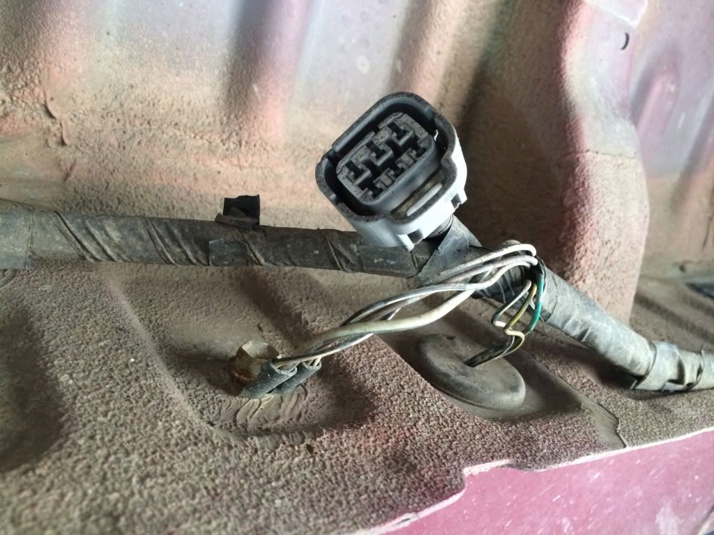
The most challenging by far was the reverse light switch, principally because I could not find the switch I really needed, an illuminated SPDT ON-ON. If it existed, this switch would accept two input leads, one from the vehicle’s reverse circuit to trigger the reverse lights when backing up, which would be the default always ON (switch in OFF position). The other side would be a 12v lead to manually activate the lights and illuminate the switch (switch in ON position). This way the manually switched circuit would never interfere with the vehicle reverse circuit. Not my idea, of course, but nice!
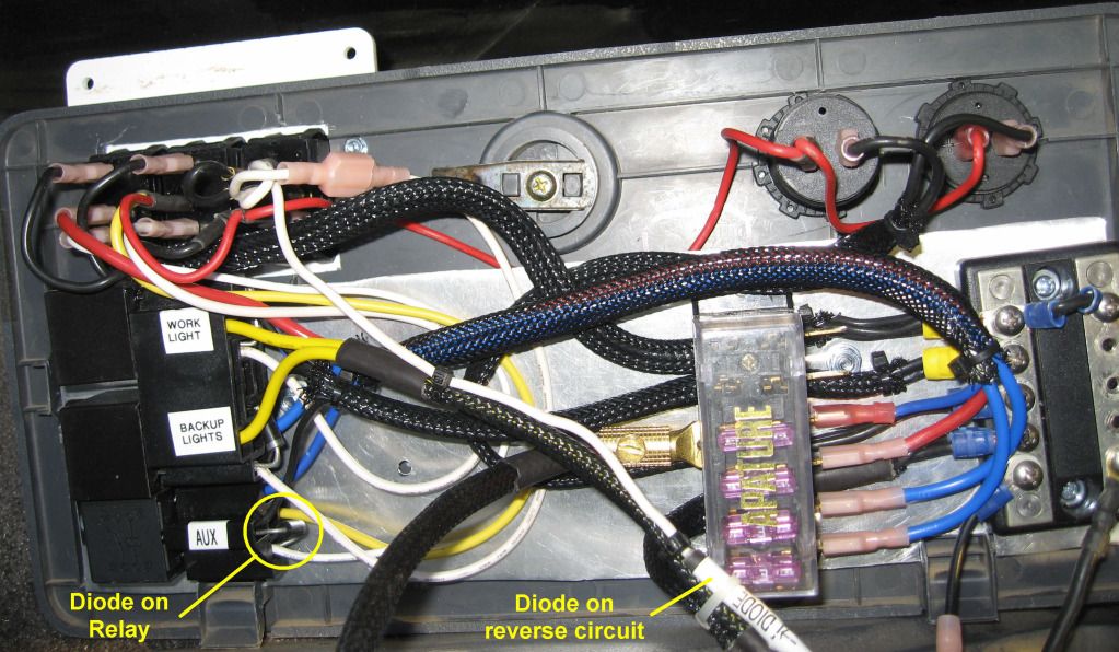
The best I could do was a DPDT ON-ON, which was fine except that the illumination connection was funky. I ended up having to jumper some switch leads to activate the illumination when the manual side was on. This in turn meant that power could flow back down the lead to the vehicle reverse circuit, which I guessed might be a bad thing. I ordered Schottky diodes to nip this in the bud. They allow current to flow in only one direction (toward the silver stripe).
According to my research these are the best diodes for this purpose. Pay attention to amperage, because they have to be stout enough to repel the amps coming at them down the wire. You can wire diodes in series for higher amperage situations. I highly recommend OddWires.com, and you gotta love the name. They do low volumes at good prices with very quick, reasonably-priced shipping.
OddWires.com
1 1N5822 STMicroelectronics Schottky Power Diode 40V 3A (20 pack) CDS-0005822
After frying the first one with the soldering gun, I actually crimped one end of the diode into a molex pin and inserted it directly into the Molex connector. The other end of the diode I crimped into a butt connector. No solder required, sealed with shrinkwrap, and, god forgive a well-meaning nerd, neatly labeled. I left a little tag end beyond the crimp so I could fold the diode lead back on itself after it was crimped. No way was it pulling out.
Since I had plenty of diodes, I added one to each relay connector to prevent whatever they call it when the relay coil de-powers and shoots high voltage back through the feed wires. Search 'relay diode' and you will see plenty about this. Of course, I then read an article explaining that this very common approach has its own drawbacks and needs a further mitigation method (search Google for "Coil Suppression Can Reduce Relay Life"). I figured I would risk the consequences.
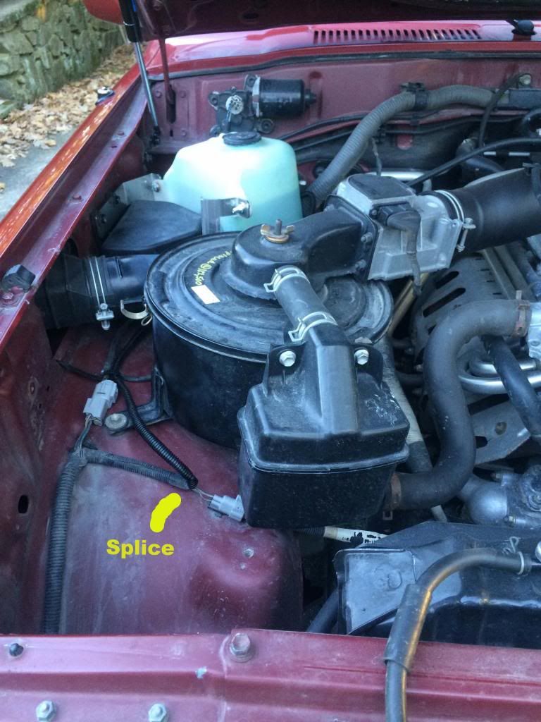
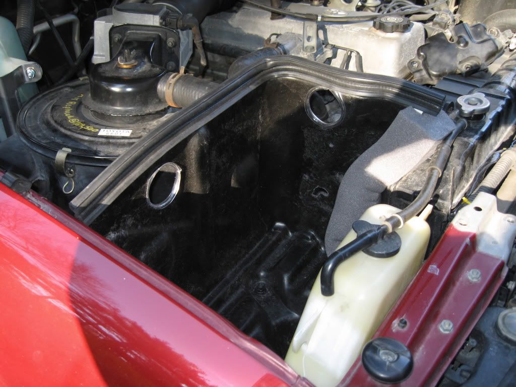
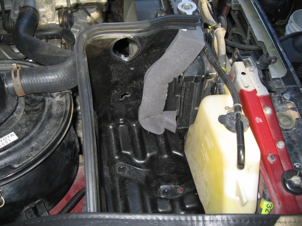
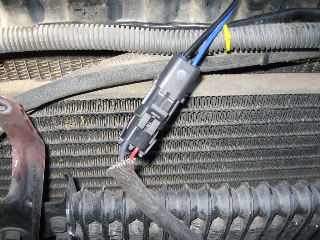
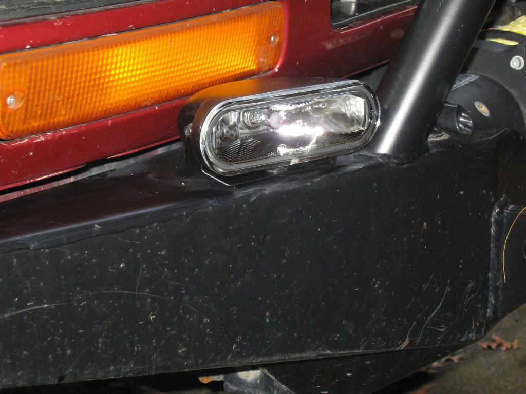
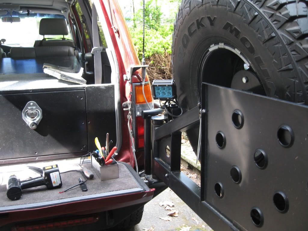
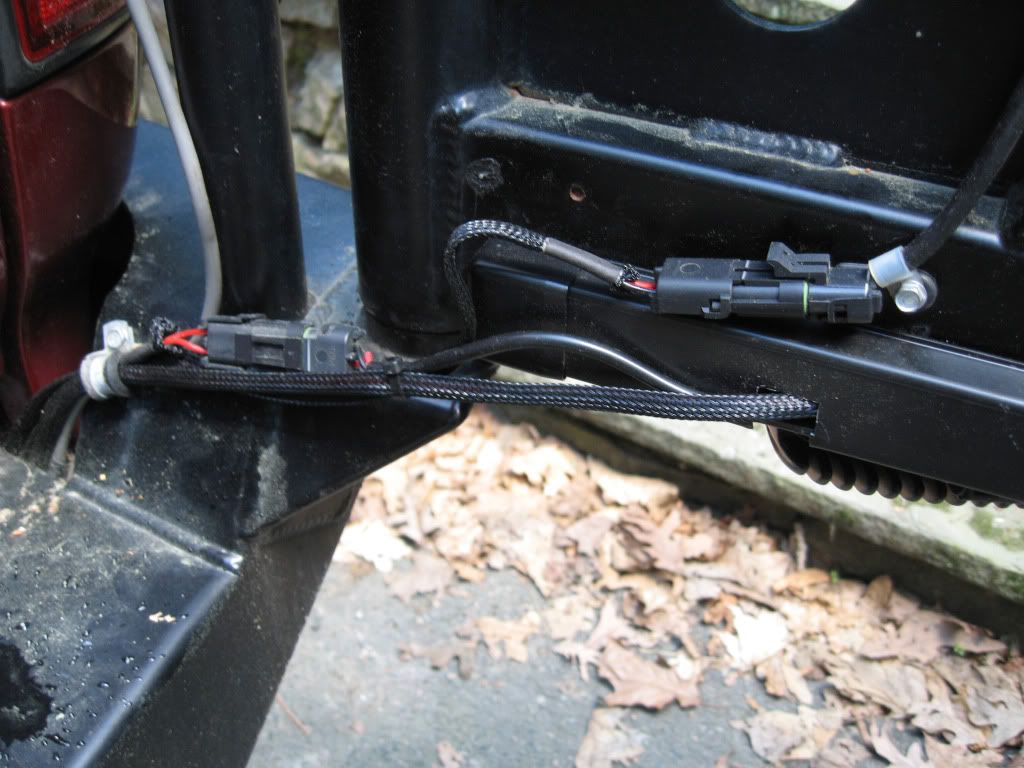
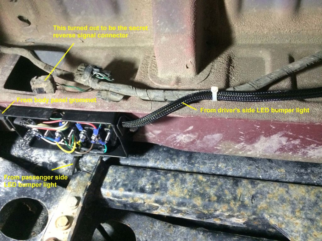
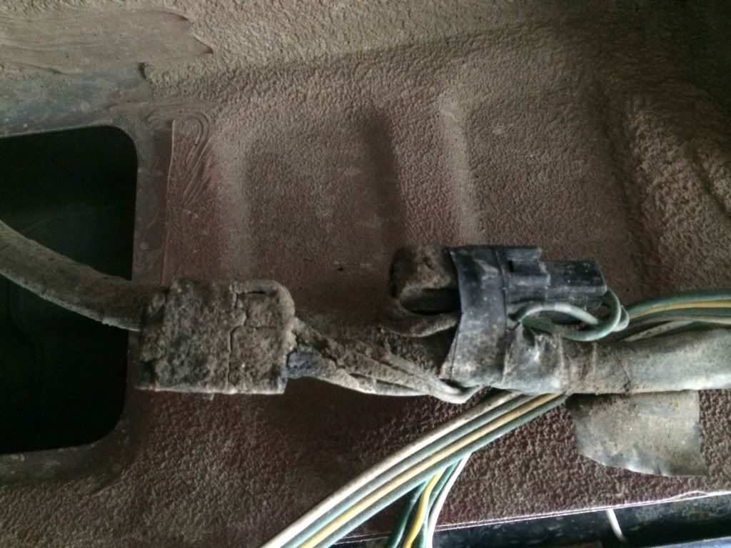
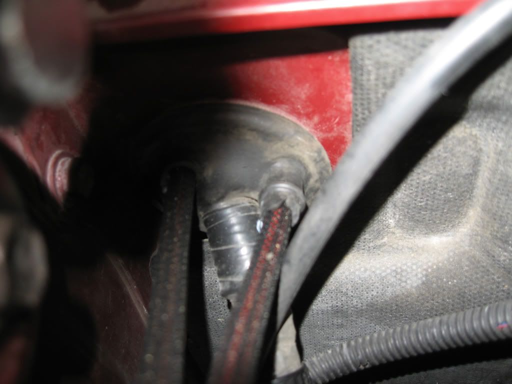
With the exception of the main power and ground, I bundled every wire that needed to connect to the vehicle into a 5-position Molex connector: power and ground for the reverse lights and the work light, plus the reverse signal lead. This made installing and removing the hatch cover an easy one-plug operation. I drilled a hole into the fore and aft walls inside the storage compartment, adding a rubber grommet to each. I fished the wires from the new lights through the same grommet that houses the trailer harness, and up through the new access hole into the compartment, where I connected them to the other side of the Molex connector. As I had not yet run power wire to the rear, I tested everything with a 12v external power supply. Ta-daaa!!
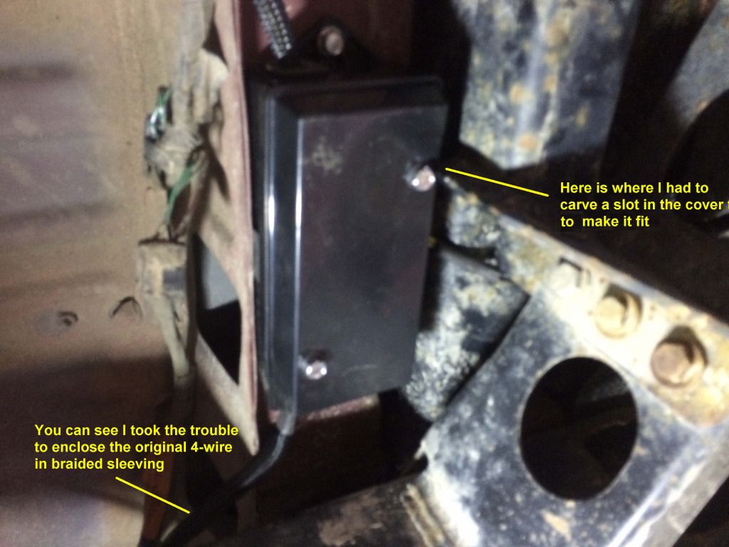
Once I knew everything worked I grouped the wires roughly by destination and encased them in ¼” braided sleeving. I locked things down with zip ties and called it a day.
By the way, the crappy-looking scratches on the hatch and body molding came with the vehicle. The hinged cover over the wheel well is just tight enough to contact the plastic. (Note to self: use a router to radius the edges.) I cut out an opening to make sure the cover had room to get past the switches.
Next up: running power from the battery to the interior and rear.