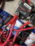
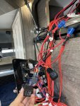
Black Series HQ Tips, Tricks, and Learning.....

paulg

New member
Thank you so much. I will do this today. It may be that the relay itself is not working so I will check the resistance on them as well. Thanks for the tips regarding where to put the multimeter. I have turned off the battery and the stair doesn’t work work so that’s confirmed. When I do turn off the main switch the pumps still work which is very weird if I am correct they shouldn’t?

I will check each wire today. I was wondering if there are any fuses elsewhere. I can’t find any.
Thanks again!

Haqi,

I stand corrected.

Drove out to where my trailer is stored after reading about your water pumps still working with the Control Panel Switch off, and learned that they still work, so, that means that they are getting 12vdc from before the Control Panel relays (in my mind anyway).

So this is what you need to check:

First the 12vdc feed to the relays is via a terminal block connection, there is 4 wires at this point, one 8GA, two 10GA (these three should be red), and one that is either 14 or 16GA, mine was yellow with a green tracer, another gentleman reported that this wire was red on his trailer. The 8GA comes from the battery, the two 10GA's go to each relay. You'll need to remove all the black tape to get to this terminal block to measure the voltage (and verify connectivity). The 14 or 16GA goes to the Control Panel Switch on the wall.

When you turn on the Control Panel Switch it activates the coil relays, in the relay connector, it was the yellow with a green tracer, the same was red on the other guys trailer. The black wire in the relay connectors goes to 12vdc return. It's easy to verify the coil voltage with the Control Panel wall switch on from the back of the relay connectors.

The output of the relays are two red 10 GA wires that go to another terminal block where they are joined with a red 8GA wire. Yes, those relays are paralleled. This 8GA wire should go to that top right circuit breaker labeled "Main". If I remember correctly, there is another wire on the hot side of the the breaker, but didn't try to figure out where it goes. You'll need to remove the black tape to verify connectivity on this terminal block also.

Hope this helps.
 

haqi

New member
Am not a expert on this, but here's my take:

Re your "staircase" is still working, am I correct in assuming that you mean your steps still extend and retract? If so, the only time they will not work is when you shut off the main 12vdc battery disconnect switch in the battery box (in my experience).

Re both water pumps still work, this tells me that your Control Panel is partially working. To confirm, shut off the Control Panel switch at the entrance, if the pumps no longer work, you've confirmed the Control Panel is at least partially working. Turn the Control Panel switch back on.

Turn off the 12vdc battery disconnect switch in the battery box, verify that your steps will no longer extend or retract. (Note: this is optional but I highly recommend shutting off the battery disconnect, when I recently did the dual relay delete mod in my HQ19, one of the wires that was always hot came out from its crimped terminal (bad crimp) on the relay connector, the result could have been interesting if it had touched a 12v return). Drop your Control Panel. I recommend that you take pictures of all the wiring before doing anything at this point. Look for any loose wires, if you can't find any, turn the battery disconnect back on, and start probing with a multi-meter. There is a 12vdc return bus on the top left corner of the Control Panel (with a bunch of black wires going to it) that you can use for the multi-meter 12vdc return.

If I remember correctly, the top right circuit breaker on the panel is the "main" breaker, measure both sides of it to make sure they're both hot, I suspect that they will be, but am not sure. There are also two boxes behind the Control Panel, one with black wires going to/from it, the other with red. Mine had clear plastic covers on on them. I suspect that you may have a issue with a loose wire or a bad connection with the "red" wired box. Am unsure as I didn't trace/mess in this particular area.

Good luck.
Hi again,

i found the problem it’s this wire labeled N20a which I have no idea what it means (attached pic) that goes to the main switch that doesn’t have power but it says 14AWG I tried to backtrack to the battery and I can’t see any wire that’s 14AWG all small ones are 12AWG. I tried using the pump line to power the mains and everything works fine so it’s just this power line that’s no power. I am wondering if it’s coming from the distributor somewhere? If you know please let me know. It’s also the one that connects to two relays. Thanks again!
 

Attachments

  • image.jpg
    image.jpg
    2.1 MB · Views: 43

haqi

New member
Haqi,

I stand corrected.

Drove out to where my trailer is stored after reading about your water pumps still working with the Control Panel Switch off, and learned that they still work, so, that means that they are getting 12vdc from before the Control Panel relays (in my mind anyway).

So this is what you need to check:

First the 12vdc feed to the relays is via a terminal block connection, there is 4 wires at this point, one 8GA, two 10GA (these three should be red), and one that is either 14 or 16GA, mine was yellow with a green tracer, another gentleman reported that this wire was red on his trailer. The 8GA comes from the battery, the two 10GA's go to each relay. You'll need to remove all the black tape to get to this terminal block to measure the voltage (and verify connectivity). The 14 or 16GA goes to the Control Panel Switch on the wall.

When you turn on the Control Panel Switch it activates the coil relays, in the relay connector, it was the yellow with a green tracer, the same was red on the other guys trailer. The black wire in the relay connectors goes to 12vdc return. It's easy to verify the coil voltage with the Control Panel wall switch on from the back of the relay connectors.

The output of the relays are two red 10 GA wires that go to another terminal block where they are joined with a red 8GA wire. Yes, those relays are paralleled. This 8GA wire should go to that top right circuit breaker labeled "Main". If I remember correctly, there is another wire on the hot side of the the breaker, but didn't try to figure out where it goes. You'll need to remove the black tape to verify connectivity on this terminal block also.

Hope this helps.
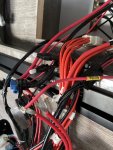
Ok then I was doing it wrong. I took the tape off of the other one and that cable has no power. See attached pic. It’s labeled yellow 20e on it. Does this mean that battery connection is bad? I see that wire on the battery terminal. Thanks
 

haqi

New member
Ok then I was doing it wrong. I took the tape off of the other one and that cable has no power. See attached pic. It’s labeled yellow 20e on it. Does this mean that battery connection is bad? I see that wire on the battery terminal. Thanks
Is is the one on the control panel breaker in the battery compartment?
 

Attachments

  • image.jpg
    image.jpg
    2 MB · Views: 34
  • image.jpg
    image.jpg
    2.1 MB · Views: 34

haqi

New member
Haqi,

I stand corrected.

Drove out to where my trailer is stored after reading about your water pumps still working with the Control Panel Switch off, and learned that they still work, so, that means that they are getting 12vdc from before the Control Panel relays (in my mind anyway).

So this is what you need to check:

First the 12vdc feed to the relays is via a terminal block connection, there is 4 wires at this point, one 8GA, two 10GA (these three should be red), and one that is either 14 or 16GA, mine was yellow with a green tracer, another gentleman reported that this wire was red on his trailer. The 8GA comes from the battery, the two 10GA's go to each relay. You'll need to remove all the black tape to get to this terminal block to measure the voltage (and verify connectivity). The 14 or 16GA goes to the Control Panel Switch on the wall.

When you turn on the Control Panel Switch it activates the coil relays, in the relay connector, it was the yellow with a green tracer, the same was red on the other guys trailer. The black wire in the relay connectors goes to 12vdc return. It's easy to verify the coil voltage with the Control Panel wall switch on from the back of the relay connectors.

The output of the relays are two red 10 GA wires that go to another terminal block where they are joined with a red 8GA wire. Yes, those relays are paralleled. This 8GA wire should go to that top right circuit breaker labeled "Main". If I remember correctly, there is another wire on the hot side of the the breaker, but didn't try to figure out where it goes. You'll need to remove the black tape to verify connectivity on this terminal block also.

Hope this helps.
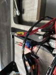
Hi Paul,
This cable doesn’t seem to have power at the control panel end but has power at the breaker. I am wondering if there is anything in the middle somewhere that’s broke or the wire itself has gone bad? What do you reckon? when I feed the pump line to the main switch everything works perfectly so now I know it’s this 7AWG line to the terminal with two relays that’s not working.

I am so glad I found your help on this and I so appreciate you driving to your camper to confirm. Thank you thank you!
 

PSea

Active member
IF you're up to it, i would strongly recommend removing all wires that connect to the batteries other than the large cables to the control panel. Everything else will result in parasitic draw and slowly kill your batteries even when the main switch is turned off. Shame on BS for doing this. I noticed on my dominator that the solar power line running from the front of the trailer was branching off before the batteries and going to the control panel. Thus, it wasn't maximizing battery charging...and it wasn't fused. I installed a new 8awg solar wire leaving the trailer behind the rear wheel and installed a victron solar charger (in the kitchen cavity). why have 17' of extra wire (running through the trailer frame) that can't be used to distance the solar panel from the trailer (ie, if you trailer is parked in the shade)? works much better...even w/ 60' of cable.
 

paulg

New member
Hi Paul,
This cable doesn’t seem to have power at the control panel end but has power at the breaker. I am wondering if there is anything in the middle somewhere that’s broke or the wire itself has gone bad? What do you reckon? when I feed the pump line to the main switch everything works perfectly so now I know it’s this 7AWG line to the terminal with two relays that’s not working.

I am so glad I found your help on this and I so appreciate you driving to your camper to confirm. Thank you thank you!

Haqi,

So, if I understand correctly, the 7GA wire that is part of the 4 wire connection on the terminal block that is on the input side of of the relays doesn't have voltage.

If so, I do not know the path of that wire back to the battery or if there are splices in the middle. I didn't bother to check backwards on mine since it was working.

Can you follow the wire to a hole in the wall or to a splice (or the big junction box with the clear cover and a bunch of red wires in it)?
If that wire goes into a hole in the wall, I don't know how to tell where it goes.... and whether there is a splice somewhere.

Am also beginning to wonder if there is more than one power feed to the Control Panel. I always thought that the Control Panel circuit breaker would shut off all power to the Control Panel if tripped. Maybe it would be a good idea to shut of the Control Panel circuit breaker (that you took the picture of) and then check to see if your water pumps will still work, if they don't, and I'm just guessing here, I'd think that there is more than one power feed to the Control Panel, if you can't see any splice points connection to a terminal block.

It does sound like you're zeroing in on the issue, and don't know if I can help you any further. The only other thing I can think of is to find a cable in the battery box that has a label that matches the 7GA at the Control Panel. The labels on mine were pretty much destroyed when I removed the black tape covering the terminal black.

Good luck!
 

haqi

New member
Haqi,

So, if I understand correctly, the 7GA wire that is part of the 4 wire connection on the terminal block that is on the input side of of the relays doesn't have voltage.

If so, I do not know the path of that wire back to the battery or if there are splices in the middle. I didn't bother to check backwards on mine since it was working.

Can you follow the wire to a hole in the wall or to a splice (or the big junction box with the clear cover and a bunch of red wires in it)?
If that wire goes into a hole in the wall, I don't know how to tell where it goes.... and whether there is a splice somewhere.

Am also beginning to wonder if there is more than one power feed to the Control Panel. I always thought that the Control Panel circuit breaker would shut off all power to the Control Panel if tripped. Maybe it would be a good idea to shut of the Control Panel circuit breaker (that you took the picture of) and then check to see if your water pumps will still work, if they don't, and I'm just guessing here, I'd think that there is more than one power feed to the Control Panel, if you can't see any splice points connection to a terminal block.

It does sound like you're zeroing in on the issue, and don't know if I can help you any further. The only other thing I can think of is to find a cable in the battery box that has a label that matches the 7GA at the Control Panel. The labels on mine were pretty much destroyed when I removed the black tape covering the terminal black.

Good luck!
Update!
I disconnected the 7AG from the breaker and reconnected. Now has power and was able to connect it directly to mains switch and everything turned on. But when I connect it to the relay it doesn’t power the control panel. Does that mean the relay has gone bad? Thanks.
 

paulg

New member
Update!
I disconnected the 7AG from the breaker and reconnected. Now has power and was able to connect it directly to mains switch and everything turned on. But when I connect it to the relay it doesn’t power the control panel. Does that mean the relay has gone bad? Thanks.

Haqi,

Now you are getting somewhere.

Ensure that the terminal block with all 4 wires are connected and that you can read 12vdc there. pull the relays out of the connectors. measure the red (or yellow green tracer) pin of the relay connectors. If 12vdc on the pins, good. If no voltage, push the wall switch once and check for voltage again. if you now have voltage, good. If no still no voltage, you're going to have to check the small wire from the the terminal block with the 4 wires in it. If I remember correctly, there is some splices, either on this wire or the the one from that comes from the Control Panel wall switch, or both. it would be a good idea to check them. Another thought would be to pull the Control Panel wall switch off the wall (don't know how it's attached) and check for voltages on both sides of the switch.

If you have voltage at the relay coil when you measured with the relays removed, then you need to verify the 12vdc return paths on the relay connectors. Measure from the relay connector pins (the ones with black wires) to the ground buss using the ohms function on the meter. You should have 0 ohms.

While it is possible for a relay to go bad, it is highly unlikely that both would fail at the same time.

Paul
 

haqi

New member
Tha
Haqi,

Now you are getting somewhere.

Ensure that the terminal block with all 4 wires are connected and that you can read 12vdc there. pull the relays out of the connectors. measure the red (or yellow green tracer) pin of the relay connectors. If 12vdc on the pins, good. If no voltage, push the wall switch once and check for voltage again. if you now have voltage, good. If no still no voltage, you're going to have to check the small wire from the the terminal block with the 4 wires in it. If I remember correctly, there is some splices, either on this wire or the the one from that comes from the Control Panel wall switch, or both. it would be a good idea to check them. Another thought would be to pull the Control Panel wall switch off the wall (don't know how it's attached) and check for voltages on both sides of the switch.

If you have voltage at the relay coil when you measured with the relays removed, then you need to verify the 12vdc return paths on the relay connectors. Measure from the relay connector pins (the ones with black wires) to the ground buss using the ohms function on the meter. You should have 0 ohms.

While it is possible for a relay to go bad, it is highly unlikely that both would fail at the same time.

Paul
Thanks Paul. I will check this tomorrow. If not I will just get rid of the relays and use a 50 amp switch instead. It seems like too much hassle and not much use in drawing power all the time with these relays. I appreciate your help! Thank you!
 

haqi

New member
Haqi,

Now you are getting somewhere.

Ensure that the terminal block with all 4 wires are connected and that you can read 12vdc there. pull the relays out of the connectors. measure the red (or yellow green tracer) pin of the relay connectors. If 12vdc on the pins, good. If no voltage, push the wall switch once and check for voltage again. if you now have voltage, good. If no still no voltage, you're going to have to check the small wire from the the terminal block with the 4 wires in it. If I remember correctly, there is some splices, either on this wire or the the one from that comes from the Control Panel wall switch, or both. it would be a good idea to check them. Another thought would be to pull the Control Panel wall switch off the wall (don't know how it's attached) and check for voltages on both sides of the switch.

If you have voltage at the relay coil when you measured with the relays removed, then you need to verify the 12vdc return paths on the relay connectors. Measure from the relay connector pins (the ones with black wires) to the ground buss using the ohms function on the meter. You should have 0 ohms.

While it is possible for a relay to go bad, it is highly unlikely that both would fail at the same time.

Paul
I did actually check the relay pins after taking off connectors. They have dc. I need to do the backtracking to the bus bar with black wires. I will report on this tomorrow. Thanks again.
 

haqi

New member
Haqi,

Now you are getting somewhere.

Ensure that the terminal block with all 4 wires are connected and that you can read 12vdc there. pull the relays out of the connectors. measure the red (or yellow green tracer) pin of the relay connectors. If 12vdc on the pins, good. If no voltage, push the wall switch once and check for voltage again. if you now have voltage, good. If no still no voltage, you're going to have to check the small wire from the the terminal block with the 4 wires in it. If I remember correctly, there is some splices, either on this wire or the the one from that comes from the Control Panel wall switch, or both. it would be a good idea to check them. Another thought would be to pull the Control Panel wall switch off the wall (don't know how it's attached) and check for voltages on both sides of the switch.

If you have voltage at the relay coil when you measured with the relays removed, then you need to verify the 12vdc return paths on the relay connectors. Measure from the relay connector pins (the ones with black wires) to the ground buss using the ohms function on the meter. You should have 0 ohms.

While it is possible for a relay to go bad, it is highly unlikely that both would fail at the same time.

Paul
Hi Paul,

I did all the above and I do get 0 Ohms on the black wires to the ground bus. Checked both if them. Also all corresponding pins have 13v. The control panel still won't get power through these relays. Not sure what that means but I checked resistance on the relays as well and don't get 0 Ohms which might be an indication that both relays have gone bad? Thanks again for any further suggestions otherwise I will have to go on to connect the wires via a switch and get rid of the relays until I install a viltron BP or order new relays.
 
Last edited:

haqi

New member
Hi Paul,

I did all the above and I do get 0 Ohms on the black wires to the ground bus. Checked both if them. Also all corresponding pins have 13v. The control panel still won't get power through these relays. Not sure what that means but I checked resistance on the relays as well and don't get 0 Ohms which might be an indication that both relays have gone bad? Thanks again for any further suggestions otherwise I will have to go on to connect the wires via a switch and get rid of the relays until I install a viltron BP or order new relays.
Update!
I just got the relays from Oreily and everything is working fine now but I will replace the relays with the Victron BP as soon as it arrives. Both relays were apparently dead (stock one in my hand). Thanks for all your help.
 

Attachments

  • 263B6115-276A-476F-98F8-363FFB7D9D44.jpeg
    263B6115-276A-476F-98F8-363FFB7D9D44.jpeg
    1.9 MB · Views: 43

paulg

New member
Update!
I just got the relays from Oreily and everything is working fine now but I will replace the relays with the Victron BP as soon as it arrives. Both relays were apparently dead (stock one in my hand). Thanks for all your help.

Haqi,

Am glad you got it figured out. While I have extremely limited knowledge on the subject, I believe your the first to experience a double relay failure.

I had emailed an friend earlier asking if he would chime in on the subject, he had an excellent write-up on removing the relays and installing a switchable circuit breaker. When I saw that you had fixed it, had to send a never mind message.

I had replaced my relays with a Victron 65A Smart Battery Protect, and wired it so that the Control Panel wall switch still controls the control panel (via the Smart Battery Protect) and didn't lose my step well lighting.

Paul
 

Forum statistics

Threads
188,304
Messages
2,905,206
Members
229,959
Latest member
bdpkauai
Top