Calling on Electrical Circuit experts.

Jay Ayala

Explorer
Hi guys,
Hey I need your help figuring out a circuit. I need to verify that this circuit will work as intended. I'll describe what I want and ask if you guys could read the schematics below. Once you have reviewed the schematics and understand what I want it to do, please give me your feedback. I think this is right but I don't really do much in the way of electrical.

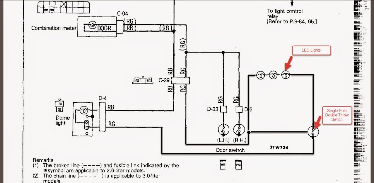
I want to augment my dome light with some additional LED lights. I want to them to come on when I open the driver side door or the passenger side door. But I don't always want them to turn on when the doors are open. My kids may fall asleep in the back and I want the option to switch just the LED lights off when not desired but leave just the dome light functioning.

Below you will see the original diagram of the dome light for the 2 door. My additional lights are shown below with a single pole, double throw switch. What do you guys think?

Original%2BDome%2BLight%2Bwiring%2Bschematic..jpg


Dome%2BLight%2Bwiring%2Bschematic..jpg
 
Last edited:

dwh

Tail-End Charlie
It would work, but putting the LEDs inline might dim the dome light (and the LEDs) when the LEDs are switched into the circuit. I would run a separate ground for the LEDs, and just switch the hot to either dome only, or both.

EDIT: Or use a triple throw and you could have dome only, LED only or both - or dome only, both on or both off for stealthy ops. :).
 

pugslyyy

Expedition Vehicle Engineer Guy
I'm in agreement with dwh - you have to lay out all the lights in parallel not series. Meaning between the RB and RG wires.
 

JamesW

Adventurer
Where do you plan on putting them? I did something similar with no switch in my own pajero,I just added holes into the existing contacts each side of the bulb holder in the existing interior light,and soldered wires onto them,which lead to LED strip light.

So if you just add a switch into the wire going to the aux LEDs,you'll find that it works they way you want.
 

Jay Ayala

Explorer
Just a few points of clarification here guys. The switch I plan on using is a Single Pole Double Throw (SPDT). Which is to say that if I put it in the first position, it completes a circuit called Normally Open (NO). If I put it in the second position, it completes a separate circuit called Normally closed (NC). There is no off position, it takes a common power supply and toggles it to either NC or NO.

Here is a close up of the back of the switch I just purchased.

SPDT%2Bswitch%2Bpicture.jpg


Someone mentioned that I should consider wiring this in parallel vs series due to an amperage draw causing the lighting to be dim. With each of these LED lights only drawing 40mA, I should be fine without noticing any dimming effects. I plan on placing four of these total so I'm sure that the circuit could provide 160mA without any adverse dimming effects.

LED%2Blights.jpg


So now having described the switch and the additional electrical loads, I want to revise the circuit design for clarity. I saw that someone mentioned I should use a Single Pole Singe Throw (SPST), but that would not complete the secondary circuit. As far as I know, a SPST only completes a single circuit when NC but has no output connector to a NO position. Right??? Taking a look at this SPST illustrates only one common and one Normally Closed output.

single%2Bpole%2Bsinge%2Bthrow%2Bswitch.jpg


This image below shows you that if I leave the SPDT switch Normally Closed in position #1, it will complete the circuit and turn ON the LED lights.

SPDT%2BPosition%2B1.jpg


However, if I toggle the SPDT switch to the second position so Normally Open, the path to ground gets diverted without lighting up the LED lights.

SPDT%2BPosition%2B2.jpg
 
Last edited:

dwh

Tail-End Charlie
Um...doesn't sound right.

A typical SPDT would have two "normally open" circuits, and one or the other would be closed depending on which way the switch is set. The other would remain open.

But a switch that has one normally open, and one normally closed, would imply that if the switch is in one position, then the normally open circuit is now closed, but the other circuit - normally closed - is STILL closed. Thus both circuits are complete.

With the switch the other way, the normally open side is once again open, but now the normally closed side has been changed to open as well.

So to me, that switch layout would imply "both open" in one position, or "both closed" in the other position.


EDIT: Also, that switch in the pic has too many contacts. A typical SPDT would have three contacts. That one has five, which further makes me think it does not behave like a typical SPDT.


EDIT again: Or...okay I can see what's going on - it's designed to change the state of both sides whenever the switch is moved. Okay, that would work, but seems needlessly complex.

AND it doesn't jibe with your description of, "There is no off position, it takes a common power supply and toggles it to either NC or NO." You described the behavior of a normal SPDT which that switch plainly isn't.
 
Last edited:

pugslyyy

Expedition Vehicle Engineer Guy
Just a few points of clarification here guys. The switch I'm plan on using is a Single Pole Double Throw (SPDT). Which is to say that if I put it in the first position, it completes a circuit called Normally Open (NO). If I put it in the second position, it completes a separate circuit called Normally closed (NC). There is no off position, it takes a common power supply and toggles it to either NC or NO.

Here is a close up of the back of the switch I just purchased.

Someone mentioned that I should consider wiring this in parallel vs series due to an amperage draw causing the lighting to be dim. With each of these LED lights only drawing 40mA, I should be fine without noticing any dimming effects. I plan on placing four of these total so I'm sure that the circuit could provide 160mA without any adverse dimming effects.

So now having described the switch and the additional electrical loads, I want to revise the circuit design for clarity. I saw that someone mentioned I should use a Single Pole Singe Throw (SPST), but that would not complete the secondary circuit. As far as I know, a SPST only completes a single circuit when NC but has no output connector to a NO position. Right??? Taking a look at this SPST illustrates only one common and one Normally Closed output.

This image below shows you that if I leave the SPDT switch Normally Closed in position #1, it will complete the circuit and turn ON the LED lights.

However, if I toggle the SPDT switch to the second position so Normally Open, the path to ground gets diverted without lighting up the LED lights.

You seem determined to try it your way. Have at it. Placing the 12V LED assembly in series with the existing lights (which are in parallel) may not work, but it is not going to damage anything.
 

Jay Ayala

Explorer
You seem determined to try it your way. Have at it. Placing the 12V LED assembly in series with the existing lights (which are in parallel) may not work, but it is not going to damage anything.
Hello pugslyyy, I appreciate your feedback very much. I am not committed to any particular "way" so to speak, I would like to install this augmented LED optional wiring and just have it work. If your opinion is that parallel would be better than I would like to discuss that further. I am not a circuit design expert and I would love it if you could guide me with designing an alternative parallel schematic.

I'll do all the work, just guide me with connection points, power supply and ground.
 

dwh

Tail-End Charlie
If I understand correctly, the goal is dome always, LED sometimes? To do it with an SPST:


spst.jpg
 

nwoods

Expedition Leader
I think the cross-connect between the switch and the other side of the LED's is going to short the circuit. I think the switch should be IN the cross-connect. But my architectural degree does not make me much of an electrical engineer.
 

JamesW

Adventurer
What DWH said is basically the way I would do it,your method is a small bit over complicated,but I can also see where you are coming from. Are you trying to avoid dropping the headliner to get the wires run,and want to take the feed from the loom going up to the headliner? It is super easy to implement, You can use your switch that you have already. If it isn't dark tonight I'll take a picture of how mine is done,all you need to do then is add in the switch to control the LEDs independently and you're done

By doing it the way you have outlined is totally fine,but you're over thinking it.
 

UK4X4

Expedition Leader
Single Pole Double Throw (SPDT)

being a push button, is it latching or momentary ?

NO=Normally open so thats a set of contacts open circuit or off
NC= Normally closed so thats a set of contacts which are on-or in contact allowing current flow

If its non latching it will only change state while being pushed

if its latching then its push for change state and push again for change back
 

pugslyyy

Expedition Vehicle Engineer Guy
Hello pugslyyy, I appreciate your feedback very much. I am not committed to any particular "way" so to speak, I would like to install this augmented LED optional wiring and just have it work. If your opinion is that parallel would be better than I would like to discuss that further. I am not a circuit design expert and I would love it if you could guide me with designing an alternative parallel schematic.

I'll do all the work, just guide me with connection points, power supply and ground.

Think of it this way - everything in a car is designed for a nominal 12 volt system, and the devices are constant voltage not constant current. Meaning that they expect to see 12 Volts and then will pull whatever current they need (or blow a fuse trying).

Since the battery is a 12 volt device, you get the correct voltage for the devices you hook up by placing them between the positive and negative terminals of the battery. Everything in your vehicle - the starter, the ECU, the radio, each and every light, is effectively in parallel between the positive and negative terminals.

The layout of a vehicle electrical system is like a ladder - the stringers are the voltage rails (12V and ground), and each device you hook up has to have it's own rung.
 

toyrunner95

Explorer
I think he is trying to run the lights in series then put an over ride switch on them so he can turn them on and off. The switch is probably a button style not a momentary. His way would work fine with the minimal draw. It's what I would do to add aN accessory to an existing circut. but I would put a fuse between the hot line into the new circut and the existing one. That way you know s which fuse to change is it blows. Led don't work it's new fuse. Nothing works. Old fuse.

You have to remember these circuts are multi use. I'm pretty sure you dome light is already an additional circut to something. You might be better off wiring up a new circut for the leds then patching into the door switches. Then put your over ride in. That way u can still turn them on and off nd utilize the door switches without taxing the original system.

Just my 2 cents
 

jlocster

Explorer
I agree with Toyrunner, I would get a BluSea fuse box and run a separate circuit. In fact, that's what I did on my ride Jay, and I used the exact LEDs you're using. My accessory LEDs don't turn on with the door switches, as I have them wired to a simple on/off switch, but I haven't found it to be a problem at all. I don't like cutting or tapping into original wiring harnesses if I don't have to. I think having accessories wired separately avoids electrical gremlins in the long run, and if problems arise, separate circuits are much easier to troubleshoot.
 

Forum statistics

Threads
188,790
Messages
2,910,234
Members
231,076
Latest member
Mikenm
Top