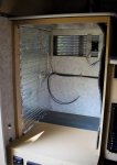
Fourwheel Camper Personalization

White Dog

Member
Thank you for taking the time to document your modifications. I don't own a truck camper but I find your work very interesting. And as a fellow woodworker, I really enjoyed your solutions to problems such as the spice rack and toilet riser.
Of course most of these projects aren't unique to FWCs. The ideas are universal and really only my thoughts. I am hoping the thread just gets the creative juices flowing for everyone. Overlanders specifically and travellers in general tend to be a pretty creative bunch.


A fellow overlander and woodworker! Realize we are forever cursed to tinker my friend. Its a burden (a fun one though).
 

White Dog

Member
Electrics - part deux!

When we last left White Dog's Grandby . . .

With the CTEK charger installed, I thought all my battery charging issues were done.

Optimistic fool!

The batteries were definitely charging quicker but not nearly as fast as I expected, in fact about half as fast. Hmmm. I measured the input a number of times with my multimeter. The rate was always about 20 amps, just like advertised. I had been thinking about installing a battery monitor anyway and now was the time to do it. I'm a retired scientist and I just feel helpless unless I have 'data'.

I have had great luck with Xantrex products so I invested in one of their Linklite monitoring systems. This unit does it right with a 'shunt' so that the meter can actually measure the number of amps going into and out of the batteries. If you want to learn more about shunts, here is what Wikipedia has to say: (Wiki on shunts) and here is what Xantrex says about their Linklite: (Xantrex Linklite). There are lots of monitors out there. All of the ones that use shunts work in the same way.

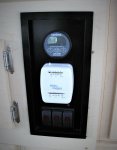
Of course, once I got the bit in my teeth, I decided that I may as well upgrade the whole front electrical panel. FWC had installed one of those electronic water level systems for the freshwater tank which I no longer needed (see above). I also wanted to recess the thermostat a bit because it was in the ideal spot to get kicked as I hop out of bed in the morning, still groggy not having had my morning coffee yet. I also replaced the OEM switches with BlueSea rockers (made by Carling I think) mostly because they light up when 'on' and I like to turn the pump and certainly the hot water heater off at night. The lights remind me. These switches have a very high cycles-to-failure rate too - more security on the road. Anyway here is what the new panel looks like.

IMG_6373small.JPG

With the monitor installed, I was ready to have a long look at the charging cycle of my batteries. I ran the batteries down to about half charge and then started the truck. Watching the battery monitor I could see the amps climb from 0 to 20 over about 30 seconds. This is what I expected. It takes the CTEK charger a bit of time to convince the AGM batteries to take a full charge. The monitor would stay at 20 amps for about 10 seconds then drop to 0.

What the *&@#^$ is going on!

I quick call to my brother, the electronics technician, solved the problem. The 10 ga. wires installed by the dealer were too small for the 20 amp load. The CTEK unit has a low voltage cutoff. It would start to charge the batteries and when at full charge, the voltage in the wires from the truck would start to drop. When it dropped below the minimum, the CTEK would turn itself off to protect the system. Once off, the voltage would climb back to normal and the CTEK would start the cycle all over.

Voltage drop (at least in this context) is simply the cumulative resistance in the wire and connectors between the electrical source and load. Where does the power go? Heat! Low voltage 12 VDC has little pressure so big wires are needed. On the other hand, it's hard to electrocute yourself with 12 VDC - not impossible but difficult. I calculated the size of wire I would need to get 20 amps 21' from my alternator to the house batteries. The industry norm for acceptable voltage drops is usually 10%. Most things will work at the lower voltage and the manufacturers want to save on the cost of large wires. Copper is expensive. In electronics, 3% is the accepted norm. It means thicker wire and more expense but more power out the other end and generally easier on equipment. I use 3%. My calculation (and yes there is an app for that) showed that I needed 6 ga. wire to get from the engine to the batteries with only a 3% loss.

This gets us to talking a bit about wire (I told you this was a rabbit hole). All wire is not the same. Standard automotive wire from places like NAPA meets the minimum requirements but generally it has relatively course strands of bare copper wire. Fine strands carry electrons more efficiently and allow the wire/cable to bend more easily and more often without breaking. 'Tinned' wire meaning each strand is coated with tin which prevents corrosion. Fine strand tinned wire moves us into either marine or aviation wire. Marine is more readily available and cheaper. I've always used Ancor brand but I'm sure there are lots of others out their. It's expensive but most good things are.

To solve the voltage drop issue meant stripping all of the 10 ga wire feeding the CTEK charger out of the truck and camper and replacing it with 6 ga marine wire. Of course the connector the dealer had installed in the box of the truck was too small and it was getting kind of corroded anyway so that had to be replaced too. While I was at it, I installed watertight glands on the outside of the camper to keep rain out and act as a stress relief for the rather fat 6 ga wire.

IMG_6383small.JPG

The smaller purple wire is for the running lights on the camper. The FWC dealer had installed this wire by splicing into the rear licence plate light leed. It too was starting to get corroded so I replaced it with 14 ga Ancor and moved the junction to the rear tail running light. This junction is out of the wet and weather but I waterproofed the junction just to make sure.

I still need to make a new connection plate for the truck. This will use a bolt-on system for the lugs on the end of 6 ga wire (covered in electrical tape in the photo above). Another winter's projects.

I tested the new-improved set up this summer. Works great. Finally! A true 20 amps going into the batteries from the truck engine all the time. That part of the system is done.

Next time: further down the rabbit hole - solar issues.
 

White Dog

Member
Electrics - On the Home Stretch for this Year!

With the CTEK module doing its magic, new heavy wire allowing the pixies to slide down the tube more easily and the Xantrex monitor keeping a watchful eye on the ever reluctant pixies, I'm pretty happy with the way the Tundra and Grandby are working together to keep the house batteries charged. But, I'm not totally out of the woods yet.

Part of the plan is to be able to drive into the backcountry, turn the key off and chill for a few days. You're reading this on an overland forum; you know exactly what I'm talking about. Another cup of coffee in the morning, napping in the afternoon, lazy evenings around the campfire. Wait, I lost my train of thought there for a moment. Back on track White Dog.

Because I can now watch how many amps are going into and out of the batteries thanks to Mr. Xantrex, I can watch the performance of the solar panels. I have two 100 w monocrystalline 12 VDC panels mounted on the roof. The manufacturer rates these at 5.52 amp 'Maximum Power Current (Imax)' output. Together, the theoretical maximum should be 11 amps. In the real world, the theoretical maximum in never reached (its a long and complicated story). However, 9 amps shouldn't be unreasonable if the panels were at the perfect angle to the sun. Mine are flat so 7 amps would be a reasonable number. Building an easy system to tilt the panels is a future project. Any examples out there other than the usual arms and bolts systems? Anyway I had never seen my panels put out more than 5.5 amps. Another stumper.

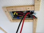
The problem became clear when I realized FWC hid a the junction box for the solar panel (and all the ceiling electrics) underneath the forward lift panel. Taking the lift panel off (6 screws) gives complete access to the box. The wires from the panels to the connecter on the roof were 10 ga. but the in the junction box FWC had reduced the wire size to 14 ga., way to small for my panels. This is kind of strange actually. I would have suspected 12 ga. for the original 90 watt panel. I would have been happier if they had used 10 ga. which is kind of the norm but there you go. I suspect that the technician at the factory just installed the wrong gauge by mistake but that's speculation.

At this point, it is probably obvious that our old and dreaded enemy, voltage drop, is making another appearance. Gad I hate that guy. The run from the panels to the CTEK unit was just short of 25', a long haul. For 14 ga. wire, I calculated the voltage drop would be about 13% at 8 amps. You can actually measure the drop by putting a multimeter set to DCV across the solar panel leads where they come out of the panel and compare that to the voltage at the input for the CTEK charger. My estimate of 13% was pretty close to the measured loss. Effectively, I was loosing about an amp to voltage drop. I told you I hated that guy.

So what to do?

A quick calculation showed that to keep the voltage drop to 3% I needed to have 10 ga. wire. The problem was how to get it from the solar panels to the batteries. For those of you that don't know, FWC runs all the electrical wires from the junction box under the lift panel forward above the headliner then behind the forward folding panel, out from behind the panel , behind the trim panels on the left side and finally behind the plywood paneling behind the kitchen cabinets. I can show part of this run.
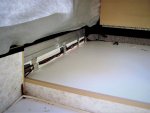
IMG_6376small.JPG

My problem was how to run the new heavier wire through the ceiling. The headliner cannot be easily removed. I was told that if I were lucky, the technicians at the factory wouldn't have attached the wires anywhere along the ceiling run and I could just attach the new wires to the ends of the old ones at the junction box and pull them through. Any guesses how that went. My dad was lucky. My sons are lucky. My brother and I aren't - ever. I guess luck skips generations.

So this was a head scratcher. A solution finally popped into my mind during morning coffee as they often do. FWC attaches thin strips of 1/8" plywood covered with decorative vinyl over top of the longitudinal aluminum ribs that form the structure of the ceiling. These hold the headliner in place and are just stapled on. If I built a new set of ribs a bit thicker, 5/16", I could sneak the wires into the rib that runs forward from the junction box to the front folding panel.
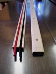
IMG_6360small.JPG

Of course this would mean making a whole new set of strips and replacing them all but to be honest, the factory ones were kind of cheap looking and starting to separate from the headliner anyway. It turned out to be a good excuse to redo something that was kind of bugging me anyway.

If you should ever get the urge to do-as-I-have-done, be aware that 5/16" is the absolute maximum thickness that these strips can be. Any thicker and they will start to interfere with the way the end walls fold up.

So now I had a plan and a nice piece of tiger maple to make the new strips. I warned you this was a deep rabbit hole.

The new wire runs from the junction box under the new ceiling strip to the front folding wall.
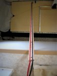
IMG_6380small.JPG

IMG_6381small.JPG

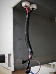
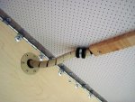
I built a small aluminum disk to hold a rubber grommet and then routed the wire through spiral loom. The wire is going to have to fold here when the roof comes down.
IMG_6382small.JPG

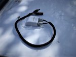
The new wire then follows the original wires behind the trim plywood at the foot of the bed. The original wires get lost behind the plywood panel backing the kitchen cabinets so I routed the new wire through the electrical outlet space in the cabinet, down the corner of the inside of the cabinet in the left front of the camper and finally connect to the original loom that is above the water tank and runs to the battery box. I replaced the original connector on the roof which was becoming a little sketchy with a new stress relieving waterproof box and all the connectors with proper MC4 waterproof type.
IMG_6385small.JPG

Jeez, looks kind of cruddy in the photo.

With a little extra wire on the roof for the day I get around to building a tilting mechanism for the solar panels, the total run is 26'. That's a long way for a solar cable but with the way the FWC is designed, I don't see any way around it.

I finished this project this afternoon. A quick check and it looks like I've probably gained my amp back. I will only be able do a complete check once I'm travelling but it looks hopeful.

I think that's it for the electrical work.

Ya, good one White Dog.

Okay, I think that's all the electrical work for now.

At this point, the Grandby is heading back to its little shed for the fall at least. Life and a new granddaughter take priority for a bit. This winter's main project will a resolution to the cause of all this grief, building a new fridge. I think this is going to be an interesting project, so I will go through that build in detail. In the end, I will end up with a camper that will do what I want it to.

Stay tuned for updates and thanks for wading through all this stuff. I hope it was at least entertaining if not useful.
 

PV Hiker

Observer
If you park toward the sun angle you can lower the front or back lift panels to gain a better angle to the sun in winter months. So that may help you while parked to elimate the flat angle to the sun.
 

White Dog

Member
If you park toward the sun angle you can lower the front or back lift panels to gain a better angle to the sun in winter months. So that may help you while parked to elimate the flat angle to the sun.

Thanks for that.

I like to park with the back of the truck (door of the camper) facing east, at least if I can. It is purely for aesthetics. I like the morning sun to come in the door of the camper. I usually sit in the open door with my morning coffee and who doesn't like to have the nice warm sun in their face. This would mean hinging the solar panels on the left because the left side of the camper would be facing south. I would probably figure out some way of tilting the panels both directions just in case I was forced to park the opposite direction. However, this is means tilting the panels on their long axis. If I do as you suggested (hinging at the front or back or both), this would be on the short axis. There would be less height and less possibility of high winds causing problems.

Hmmm . . .

Now you have me thinking.
 

White Dog

Member
So the Grandby is all done then? - Not a chance!

In the first sentence of this thread, I admitted I was a compulsive tinkerer. Just can't leave it alone. If you get that, welcome to the club. It's a lifelong addiction with no cure I'm afraid.

I have three projects on the books. The first is to build and install a gas strut lift system very similar but not quite the same as FWC now installs as standard equipment. Back in 2012 when our Grandby was built, it wasn't even an option. I've asked FWC if they sell a kit. They don't - dealer install only and the price is $725 CAD. I can still lift the roof with the two solar panels quite easily but that will change over time. Besides, why work so hard. My cousin-in-law and her husband bought a Grandby last year and sent me this photo.

FullSizeRendersmall.jpg

With the Suspa part number, I can order the exact same struts FWC uses. At $31 USD, the price is reasonable. I'll probably order a spare just in case one fails while I'm traveling. I plan on making a bit beefier mounts than FWC uses but by now you've probably figured out I like to overbuild.

FWC uses a decent quality fuse box to protect the wiring system. Nothing wrong with it at all.

IMG_6388small.JPG
But my background is in marine electrical systems and I prefer circuit breakers. They let you see at a glance if a circuit has tripped, allow you to reset it without having to look for the box of spare fuses you put somewhere (and of course you don't have the right size) and they also let you turn off a circuit easily if you need to do some work on it. And when does the fuse pop - at night! I have a box of BlueSea circuit breakers kicking around so the cost will be modest. FWC leaves lots of space behind this fuse box so doing the upgrade will be pretty straight forward.

And finally . . .

Here is the big one.

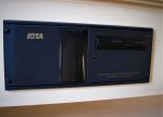
IMG_6387small.JPG

A Dometic compressor fridge used to live here. Remember I said someone in the industry described it as: "A good idea poorly executed". Even with all the electrical upgrades I've done, using this fridge is not going to give me the self sufficiency I was hoping for. At 30 C, the compressor is running 100% of the time at 4.5 amps. That's unacceptable to me. The fridge is poorly insulated and doesn't take advantage of the potential of its Danfoss D35 compressor. I had a long chat with Mario from AT Trailers at the BC Overland Rally. He was kind enough to tell me how they build theirs, who supplies their compressor systems and a bunch of other good ideas. Thanks Mario. I appreciate it. I hope to be able to sell the old Dometic for close to enough to by the new compressor system then build my own over-insulated box to fit the existing opening. I should be able to cut down the electrical consumption by 50%. Again, building custom fridges like this has been done in the marine world for a long time. Overlanders are just catching up. I will probably start a new thread for this build because I think it has greater interest than just FWC.

So those are my major projects for the winter. With all the other stuff I get mixed up in, that's enough.
 

WanderingBison

Active member
Love your post and build ... we obviously have to spend some time around a campfire. I suspect we are very like minded ... obsessed


Sent from my iPhone using Tapatalk
 

XJINTX

Explorer
Just WOW, I wish I had your skills!!! I am "contemplating" a build. I want / need space for cooking supplies. I never slide my bed out so I have room next to my sink before the bed to set something. I am thinking about a box type cabinet. I can simply move it down to floor or seat when camper is closed up. Move the box up onto counter when camped. It would give me space for extra cooking supplies and such. Have you thought about anything like this? I'd pay for research and development of my prototype ;)
 

White Dog

Member
After sitting around my share of campfires, I think the one thing I've learned is to listen respectfully to everyone's ideas. They won't always be what I would do but I admire the genius. I never met someone who doesn't teach me something - never. My only turnoff is the person (or more likely YouTube video) that starts with "The best . . ." or "The ultimate. . .". If I had to give any suggestion (reluctantly), it would be trust your ideas and build a simple trial version. If it works, keep it, if need be tweak it and at worst, discard it, using the experience to come up with a more functional idea. Never be afraid to fail. Trust yourself.
 

Cummins_expo

Adventurer
This thread is awesome! Love the small mods that make lie so much easier. We parked in front of a Container store and they let us run in and out until we found a perfect fitting items
 

Forum statistics

Threads
188,040
Messages
2,901,500
Members
229,411
Latest member
IvaBru
Top