GeoTracker90
Adventurer
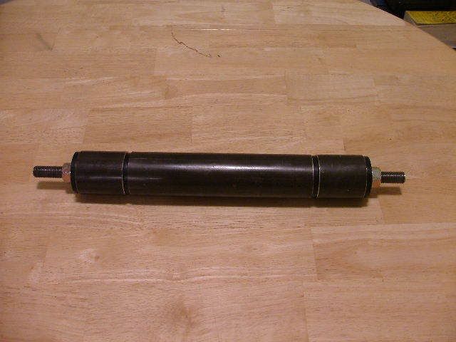
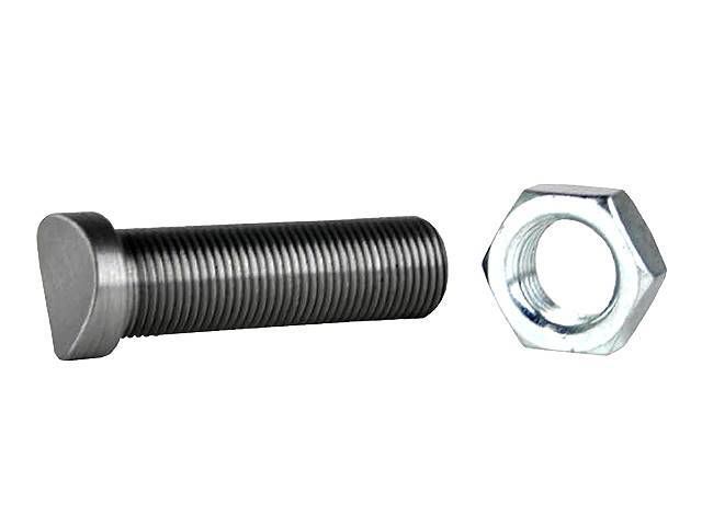
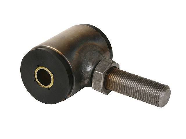
Adjusting for toe should be pretty simple if you added a threaded insert and a bushing with a threaded stud to the inboard side of the trailing arm. Picture of the bushing...
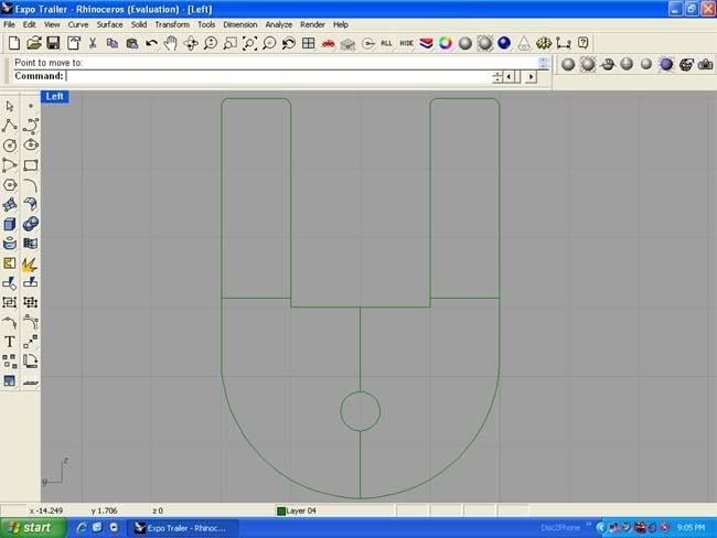
For camber I would have to make the outer trailing arm mounts slotted with a plate to lock in the camber adjustment such as ...
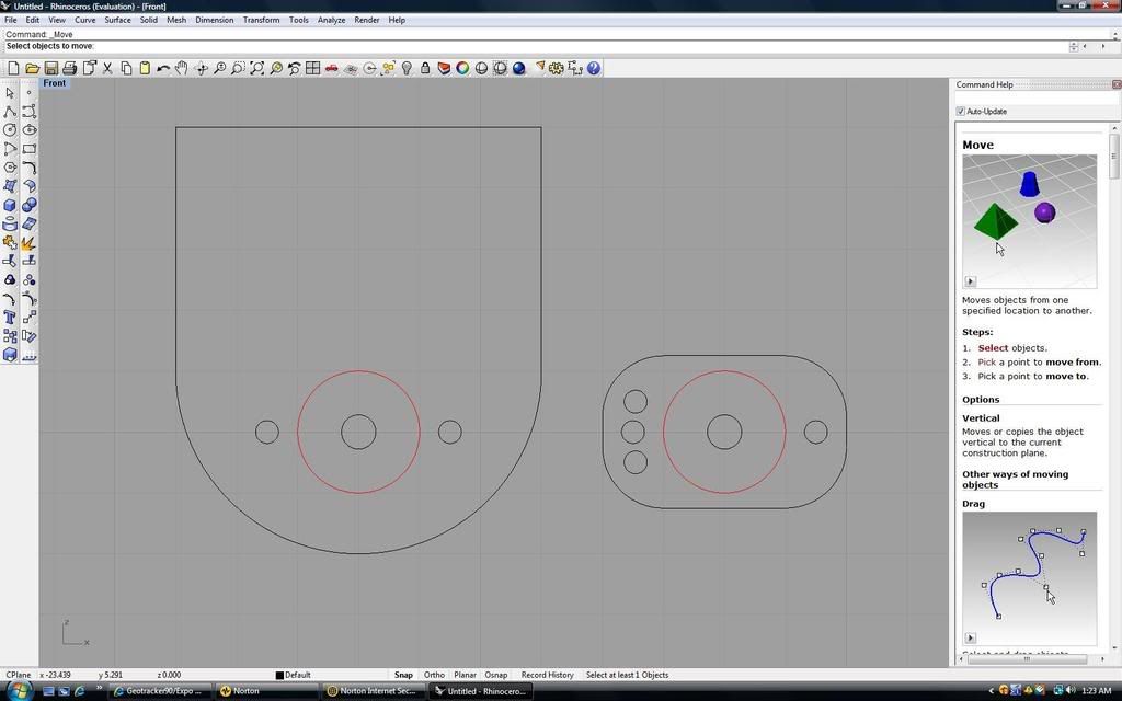
I forgot to show that on the larger bracket, the center bolt hole needs to be slotted. The red circle represents the OD of the bushings. The camber plate is attached to the larger bracket and locked into position with the two outer bolt holes (3/8") as well as the bushing's 9/16" bolt. This set up would be used on both the inner and outer sides of the outer trailing arm bushing.
Confused yet? There would be no gaurentees that this would allow you to get the alignment spot on, but it would help get it pretty close and compensate for any movement of the metal as I welded up the trailing arms.
What do you think?
For camber I would have to make the outer trailing arm mounts slotted with a plate to lock in the camber adjustment such as ...
I forgot to show that on the larger bracket, the center bolt hole needs to be slotted. The red circle represents the OD of the bushings. The camber plate is attached to the larger bracket and locked into position with the two outer bolt holes (3/8") as well as the bushing's 9/16" bolt. This set up would be used on both the inner and outer sides of the outer trailing arm bushing.
Confused yet? There would be no gaurentees that this would allow you to get the alignment spot on, but it would help get it pretty close and compensate for any movement of the metal as I welded up the trailing arms.
What do you think?
Last edited: