You are using an out of date browser. It may not display this or other websites correctly.
You should upgrade or use an alternative browser.
You should upgrade or use an alternative browser.
How to make a cheap isolated dual-battery setup for $50
- Thread starter evldave
- Start date
snare
Adventurer
I went with a Samlex 160 ACR (it is a dual voltage sensing relay) that i found with an open box price on Amazon Marketplace. Works perfectly, and use my own $5 switch to make it switchable and can do self jump.
That, with a solar charge controller and a 100watt panel, and I am all set.
That, with a solar charge controller and a 100watt panel, and I am all set.
DRLexpress
Observer
I ordered parts for original setup in this thread plus a couple extras. I want to play with a timer like elsewhere in the thread but use a cheap china/amazon timer, if it fails I'll just jump it and will have the original setup. Also going to have volt meters for each battery. Using the Cole-Hersee 80amp called out as "good"
My question- How hot should the solenoid get in operation? Some of the stuff started coming in yesterday so I had to play with it. With no load going through the contacts after an hour or two the IR temp gun would settle on around 148*. Is that normal? Been around these all my life just never noticed if they get that warm.
Doug
dwh
Tail-End Charlie
Most are rated like -40c to +85c which would be around +185f. So, it's within spec.
Having the electromagnet coil constantly energized will create some heat. But I have never checked mine so I have no idea how much heat.
The coil is made of fine copper windings. There can sometimes be a short in the windings, which doesn't necessarily stop it from working, but can make it draw more amps (which would end up as more heat).
I'd check the amp draw on the coil and if it's within spec then I wouldn't worry about it.
DRLexpress
Observer
...
I'd check the amp draw on the coil and if it's within spec then I wouldn't worry about it.
Thanks for the reply. I am probably making a problem where one does not exist while waiting for the rest of the parts show up. I had checked the amp draw already--
.61 amps at 12.02 on bench with power supply, .55 at 12.6 using the van battery. With the van running at 14.4 volts it will be better. The box did not give a spec, I guess I need to do a little research.
Thanks
Doug
patoz
Expedition Leader
Having the electromagnet coil constantly energized will create some heat.
DWH, would this be true for the Master and Ignition switched constant duty solenoids used in the power circuits for an Ambulance body also?
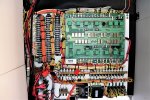
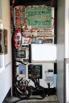
These pictures are just for reference, but you can see the two solenoids located in the lower left corner of the first picture, and about midway down in the second picture. The top one (R1) is the Master solenoid and is rated at 12VDC, and the other one (R30) is the Ignition switched solenoid and is rated at 15VDC. Neither solenoid has an Amp rating listed on it, but I'm trying to do some research on them now.
The Master (R1) gets too hot to touch in about 4 -5 minutes once 12VDC power is turned on to it.


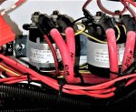
This is an enlargement of the two solenoids, and the picture has been rotated 90° counterclockwise so the labels can be read.

dwh
Tail-End Charlie
Thanks for the reply. I am probably making a problem where one does not exist while waiting for the rest of the parts show up. I had checked the amp draw already--
.61 amps at 12.02 on bench with power supply, .55 at 12.6 using the van battery. With the van running at 14.4 volts it will be better. The box did not give a spec, I guess I need to do a little research.
Thanks
Doug
Half an amp sounds about right.
dwh
Tail-End Charlie
DWH, would this be true for the Master and Ignition switched constant duty solenoids used in the power circuits for an Ambulance body also?
These pictures are just for reference, but you can see the two solenoids located in the lower left corner of the first picture, and about midway down in the second picture. The top one (R1) is the Master solenoid and is rated at 12VDC, and the other one (R30) is the Ignition switched solenoid and is rated at 15VDC. Neither solenoid has an Amp rating listed on it, but I'm trying to do some research on them now.
The Master (R1) gets too hot to touch in about 4 -5 minutes once 12VDC power is turned on to it.
View attachment 429140
View attachment 429141
This is an enlargement of the two solenoids, and the picture has been rotated 90° counterclockwise so the labels can be read.
View attachment 429142
Um. Well, in the previous example, it was heating up due to the coil being energized, but with no load through the the main contacts. The amp draw of the coil being half an amp - continuous - it makes sense that it could eventually get up to 150f. Especially if it's not bolted to a larger heat sink like a firewall.
A secondary source of heat is the current through the main contacts. Those contacts will wear over time. The heavier the amp load being switched, the faster they'll wear. Since you can't disassemble it and inspect the contacts, all you can do is check the resistance through the main contacts with the coil energized and compare that to whatever the spec is on a new one.
A quick check that I might try would be to unhook the wiring to both solenoids and then energize the coils one at a time and compare the resistance through the main contacts. Those solenoids are similar enough that the resistance should be about the same. If the R-1 is higher, then I'd be thinking worn contacts.
While I was at it, I'd probably also check the amp draw of the coil just because.
I do wonder why the coil of one solenoid is rated 12v and the other 15v...but the solenoids are obviously somewhat different so it might not be significant. Can't read the model numbers on either one, but Grainger's carries White-Rodgers.
patoz
Expedition Leader
Um. Well, in the previous example, it was heating up due to the coil being energized, but with no load through the the main contacts. The amp draw of the coil being half an amp - continuous - it makes sense that it could eventually get up to 150f. Especially if it's not bolted to a larger heat sink like a firewall.
A secondary source of heat is the current through the main contacts. Those contacts will wear over time. The heavier the amp load being switched, the faster they'll wear. Since you can't disassemble it and inspect the contacts, all you can do is check the resistance through the main contacts with the coil energized and compare that to whatever the spec is on a new one.
A quick check that I might try would be to unhook the wiring to both solenoids and then energize the coils one at a time and compare the resistance through the main contacts. Those solenoids are similar enough that the resistance should be about the same. If the R-1 is higher, then I'd be thinking worn contacts.
While I was at it, I'd probably also check the amp draw of the coil just because.
I do wonder why the coil of one solenoid is rated 12v and the other 15v...but the solenoids are obviously somewhat different so it might not be significant. Can't read the model numbers on either one, but Grainger's carries White-Rodgers.
1. The solenoids are bolted to a 9/16" thick plywood panel, so no heat sink there.
2. If these are the original solenoids, they are 12 y/o, and I thought about the contact surface condition also. This being an ambulance, most of their use was with high amp loads from a combination of halogen, strobes, and LED warning and flood lights.
3. I can definitely test both with a meter and compare the results. The one that's rated at 15 VDC is slighter larger that the one rated at 12VDC. It is ignition switched, so I wonder if the higher vehicle charging voltage would have anything to do with that.
Thanks for the suggestions and after Christmas is over, I'll get out there and do some testing to see what I can find out.
DRLexpress
Observer
Half an amp sounds about right.
Thanks, I'll quite trying to fix something that isn't broke.
Doug
dwh
Tail-End Charlie
3. I can definitely test both with a meter and compare the results. The one that's rated at 15 VDC is slighter larger that the one rated at 12VDC. It is ignition switched, so I wonder if the higher vehicle charging voltage would have anything to do with that.
I would expect any DC wiring to operate at vehicle charging voltage (12v+). Unless they've engineered some way to reduce the voltage to the R-1 coil, it should never see a voltage as low as 12v unless the batteries are getting pretty low.
Which is why it seems a bit hinky to me. We know they had solenoids available that could handle 15v, so why not use them in both positions?
And what's up with those coil ratings to begin with? I would expect solenoids like that to be rated like "12v nominal", which would be a range of like 10v-15v. White-Rodgers labeling like they did makes me think that those are specific (max) voltages, as opposed to voltage ranges.
And if the coil on R-1 is only rated to a max of 12v, but is always operating at a higher voltage, I suppose that could also cause overheating by making the electromagnet constantly pull harder than it should.
patoz
Expedition Leader
I would expect any DC wiring to operate at vehicle charging voltage (12v+). Unless they've engineered some way to reduce the voltage to the R-1 coil, it should never see a voltage as low as 12v unless the batteries are getting pretty low.
Which is why it seems a bit hinky to me. We know they had solenoids available that could handle 15v, so why not use them in both positions?
And what's up with those coil ratings to begin with? I would expect solenoids like that to be rated like "12v nominal", which would be a range of like 10v-15v. White-Rodgers labeling like they did makes me think that those are specific (max) voltages, as opposed to voltage ranges.
And if the coil on R-1 is only rated to a max of 12v, but is always operating at a higher voltage, I suppose that could also cause overheating by making the electromagnet constantly pull harder than it should.
Yes, it does seem strange they would use two different solenoids when they are carrying practically the same load.
![sshot-2017-12-26-[1].jpg sshot-2017-12-26-[1].jpg](https://forum.expeditionportal.com/data/attachments/334/334435-b6deb940edc820cbd0ec754c68eda81b.jpg?hash=tt65QO3IIM)
Last edited:
dwh
Tail-End Charlie
Yes, it does seem strange they would use two different solenoids when they are carrying practically the same load.
View attachment 429239
Well, that diagram doesn't show anything about the loads the solenoids are carrying, other than they are both wired with #2 and feeding into the main board. One could be carrying 50a and one 200a. Dunno.
If you can get the numbers off the labels and determine the specs of the solenoids that would be important.
For instance if both solenoids have the same amp rating on the main contacts, like 100a or whatever, then it wouldn't matter if you replaced the R-1 solenoid with the same part number as the R-30. Same if the R-30 solenoid had a higher amp rating than the R-1 - it won't hurt to replace the R-1 with a higher rated part.
But if the R-1 solenoid has a higher amp rating than the R-30, then you'd need to find a replacement with the same or higher amp rating as R-1 on the main contacts AND a higher voltage rating on the coil.
Last edited:
patoz
Expedition Leader
If you can get the numbers off the labels and determine the specs of the solenoids that would be important.
I'll work on this and see what I can find out, but it probably won't be today. I woke up with a bad sinus headache, and still have it.
Welcome to Florida... where you can run the A/C and Heat in the same day!
Similar threads
- Replies
- 7
- Views
- 1K
- Replies
- 0
- Views
- 171
- Replies
- 11
- Views
- 2K
- Replies
- 3
- Views
- 421
