Jay Ayala
Explorer
Hi guys, and welcome to the documentation on How To "RETROFIT" a Cruise Control into ANY Gen 1.
This thread will help anyone determine if this is a feasible project for him to try. The goal of this thread is to formally document how I performed this retrofit on my 1989 Dodger Raider. I have completed the project and it is 100% operational. It took me a really long time, a lot of research, a lot of verification, a lot of effort, and a lot of determination. My body is actually sore from this job. Hopefully all of us Gen 1 owners will now have the option of having a factory Cruise Control system. I've have done a lot of legwork that I will share with you guys on the message forum. The job really is up to you to perform.
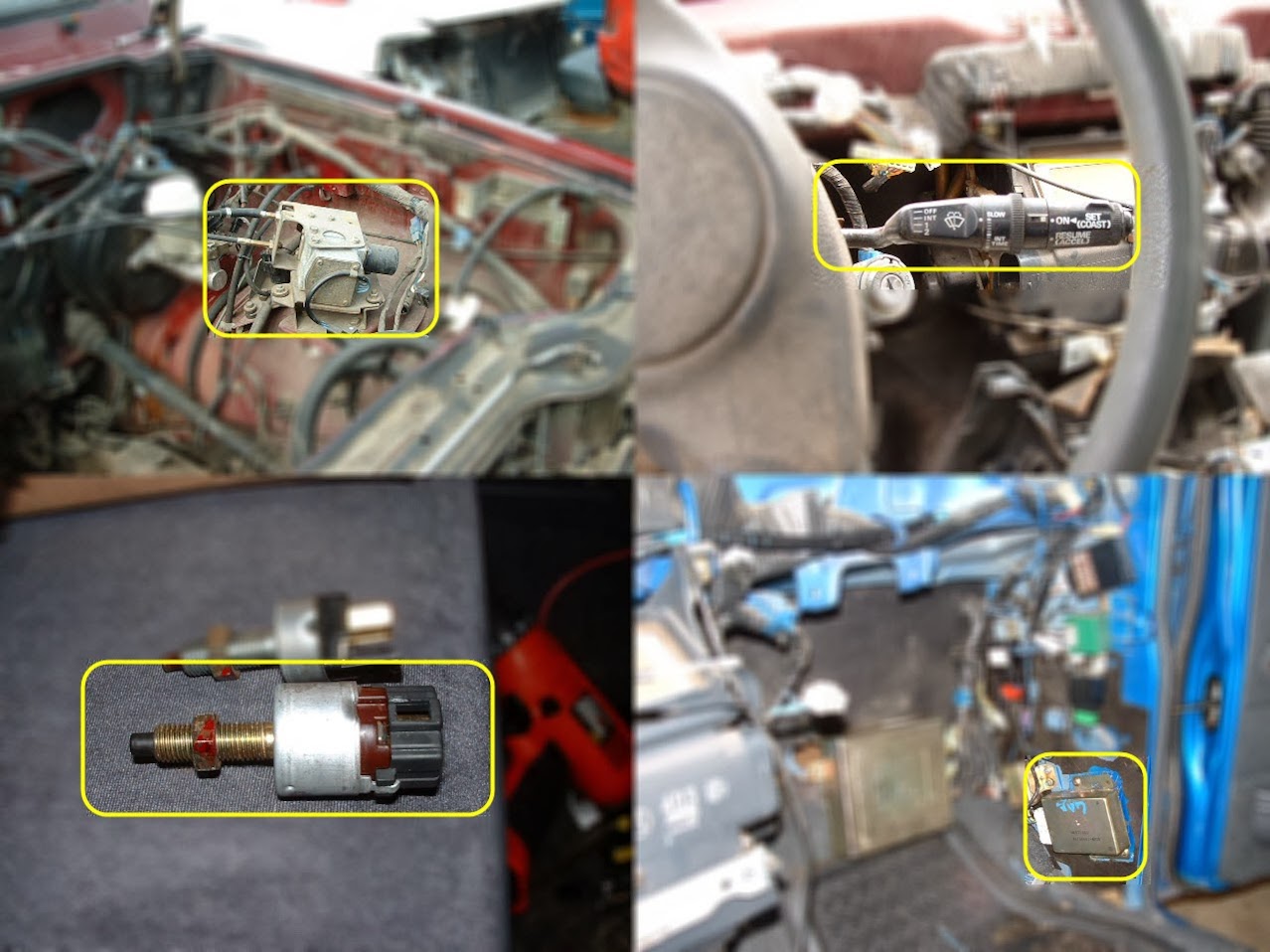
You will need to remove this unit completely. There are only two small screws holding it in the steering column. There is 1 ground wire from the Switch to the steering column, remove that along with the switch. There are 2 separate wiring harnesses that connect from the switch to the main vehicle wiring, take those 2 harnesses too. Also very important, take both mating wiring harnesses plus 6"-8" worth of wiring beyond the harnesses.
Cruise Control Servo motor.
To remove this there are 3-12mm bolts holing the servo to a mounting base. Also you WILL need to take both of the throttle cables that go to: One goes to the Throttle Body, and the other goes to the Throttle Pedal. The firewall penetration has a plastic clip that holds the Throttle Cable in place. It is very important to take your time, and be careful when removing this clip. I used a pair of long needle nose pliers to gently squeeze the plastic clips together to allow it to pass through the square hole for the firewall penetration. Also you will need to take the wiring harness. In addition you will need to take the mating wiring harness and about 6"-8" worth of wiring beyond the harness that connects to the main vehicle wiring.
Break light Switch.
The break light is different for the Cruise Control system then in our Gen 1's. Our Gen 1's have a two (2) prong break switch. Whereas the Cruise Control System needs to have a break switch with four (4) prongs. It was an easy task to remove the break light switch. You will need to take the switch. Also you will need the wiring harness that connects directly to the switch plus 6"-8" worth of wiring beyond the harnesses that connects to the main vehicle wiring.
Cruise Control Computer/Brain.
This is pretty easy to find, and very simple to remove. There are two Phillips screws holding the brain in place. Simply remove the screws and disconnect the wiring harness. You will also need the wiring harness that connects directly to the Brain plus 6"-8" worth of wiring beyond the harnesses that connects to the main vehicle wiring.
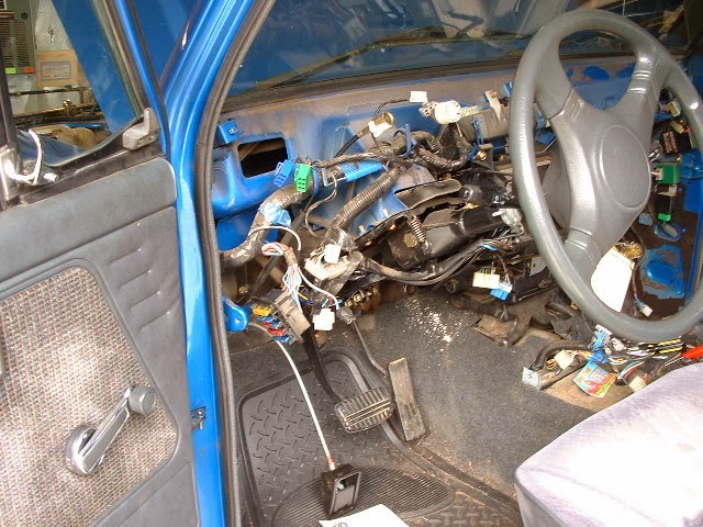
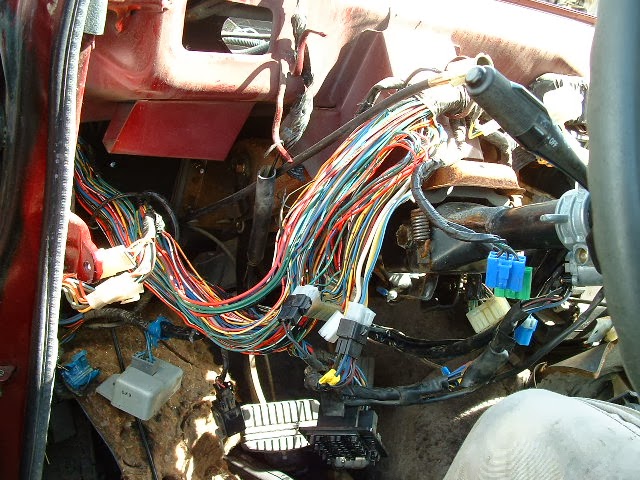
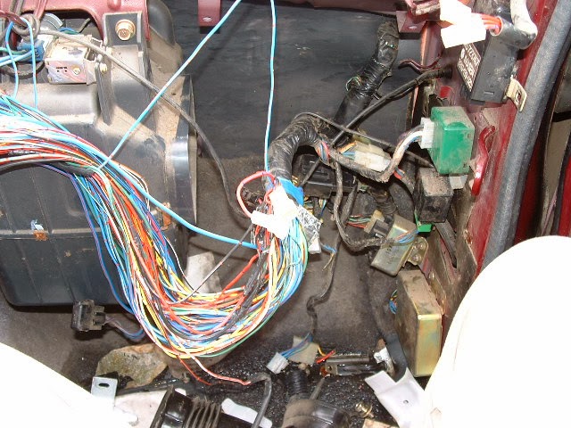
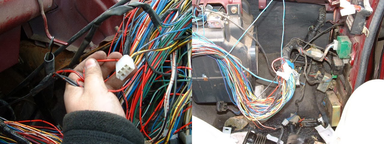
If you want, you can remove the wiring intact but that is a lot of extra work. I've done the bulk of the work in that manner and in retrospect, I could have just done as described above. It would have been a lot simpler and it wouldn't have taken me so much time to remove at the junkyard (I originally spent 4 hours removing all of the components and the wiring intact. Of course you have to remove the dash, and unwrap the electrical tape along the wiring, and it was just a mess and there are so many wires that are all different colors and similar colors I got lost several times and had to start all over.) I highly recommend doing it as described above without removing the wiring intact.
However if you plan on removing the wiring intact, expect to see this:
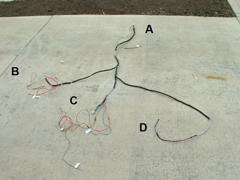
The distance between Harness A & C should be about 7'-0"
The distance between Harness A & D should be about 10'-0"
As you can see in the picture there are several wires that need to be routed to specific spots on the vehicle. Most of these will be wire through taps no longer then 24" from the corresponding harness. I will now break down how I created each individual wiring harness and what taps come off of them. I will be refering to the wiring numbers from the diagrams so check them often.
.....Harness A - Cruise Control Unit......
Wires #10 (BLK) & #11 (WHT-BLK) are ground wires. I tied them together and ran one BLK wire 24" for ground. Wires #13 (BLK-BLU) & #14 (BLK-WHT) are OverDrive Off wires. I ran individual BLK-WHT 24" wires for OverDrive Off. (depending on if you are working with a 4cyl or a 6cyl it Wires #13 and #14 will have to be routed to the passenger side kick panel, 6cyl, or driver side kick panel, 4cyl.) Wire #17 (RED) is Computer Diagnostic connection. I ran one individual RED 36" wire for Computer Diagnostic connection.
.....Harness B - Cruise Control Switch.....
Cruise Control Unit wire #2 (BLK-YEL) & #15 (YEL) are routed from Harness A to about 3/4 and 1/2 way along Branch B as shown. I ran one 12guage BLK-YEL wire about 24" for Power. I ran one YEL 36" wire for speed sensor. Cruise Control Switch wire #3 (RED-BLU) is a power wire. I ran one RED-BLU 30" wire for power. Cruise Control Switch wire #2 (RED-BLK) is a ground wire. I ran one BLK 30" wire to Ground.
.....Harness C - Break Switch......
Break Switch wire #2 (GRN-RED) is tapped to a power wire. I ran one GRN-RED 8" wire for Power. Break Switch wire #3 (GRN) is tapped and routed to the Hazard switch. I ran one GRN 8" wire for Hazard switch.
.....Harness D - Cruise Control Servo.....
This is the easies of them all. Just don't make the actual harness connections until the wires have penetrated the firewall. That's it.
Cleaning up the wiring.
I used what is called spiral wrap to clean up my wiring. I used 1/4" spiral wrap to organize my wiring bundles. It helped out greatly in that I was able to move this wiring system around relatively easy once I got the wiring taken care of. I cut the 20'-0" length of spiral wrap into 4"-6" pieces and started at the main wiring harness. Then I just followed it out slowly making sure not to confuse what wires were assigned to which bundles. Then slowly I made it a clean connection that looked near stock. I suppose you could also use the plastic corrugated wiring conduit. But I prefer the look of the spiral wrap myself. But everyone has their particular preferences.
You will have to remove the 2-prong break switch. The wiring harness that connects to the old 2-prong break switch contains 2 of the wires that you will use, so keep these in mind. When replacing the 2-prong switch with the 4-prong switch you should have two 8" wires dangling from the new Break Switch wiring harness. Those connect to the wires that were in the old 2-prong Break Switch. See diagram for color scheme.
There are 3 tricky connections to make, other then these 3 connections, the rest should all be pretty straightforward. Also there is 1 Harness conversion that you will have to perform to allow for use of the Windshield Wipers.
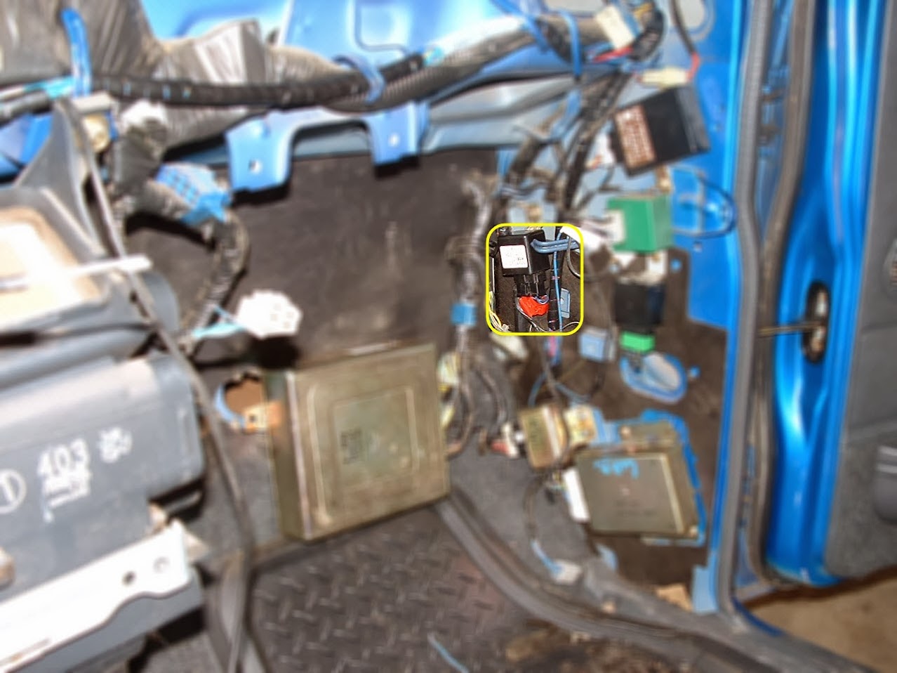
Tricky connection #1: From the Cruise Control Unit wire #14 (BLK-WHT) needs to be routed and tapped into the BLK-WHT wire of the OverDrive Off Relay. Make this connection as close as you can to the relay.
Tricky connection #2: From the Cruise Control Unit wire #13 (BLK-BLU) needs to be routed to the same BLK-WHT wire of the OverDrive Off Relay. Make this about 1" further away from the OverDrive Off Relay.
Tricky Connection #3: From the Cruise Control Unit wire #15 (YEL) needs to be routed to the vehicle speed sensor. This is probably the last connection you will make. This will have to wait until the dashboard is placed back on the vehicle. Once it is placed back on, the wire should be routed to the following screw on the rear of the instrument cluster.
Tricky connection #1 & #2. See the Red Connectors off the realy?
Tricky connection #3 Best method is to use one of those screw type connectors.

Harness conversion is really pretty simple. You will have to clip the wires from the freshly installed Cruise Control/Wiper combo switch and re-connect the harness from the older Windshield Wiper switch. The color scheme for the wires is identical, and you will not have to modify anything. Just follow the color scheme and it will match up directly to the older style harness.
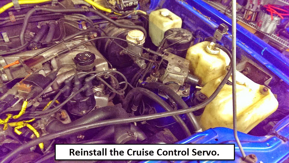
Once all of the wiring is in its place reinstall the Fan Blower and the dash. The Cruise Control Servo can be directly bolted to the Fender wall, that is how I installed it. You will have to remove the current Throttle Cable and replace it with the two that are connected to the Cruise Control Servo.
As always,
thanks for reading.
Jay
This thread will help anyone determine if this is a feasible project for him to try. The goal of this thread is to formally document how I performed this retrofit on my 1989 Dodger Raider. I have completed the project and it is 100% operational. It took me a really long time, a lot of research, a lot of verification, a lot of effort, and a lot of determination. My body is actually sore from this job. Hopefully all of us Gen 1 owners will now have the option of having a factory Cruise Control system. I've have done a lot of legwork that I will share with you guys on the message forum. The job really is up to you to perform.
- Back story:
- Components:
- Cruise Control Servo motor.
- Cruise Control/Windshield Wipers Combo switch on the steering column.
- Break light Switch.
- Cruise Control Computer/Brain.
- Removal from Donor:
You will need to remove this unit completely. There are only two small screws holding it in the steering column. There is 1 ground wire from the Switch to the steering column, remove that along with the switch. There are 2 separate wiring harnesses that connect from the switch to the main vehicle wiring, take those 2 harnesses too. Also very important, take both mating wiring harnesses plus 6"-8" worth of wiring beyond the harnesses.
Cruise Control Servo motor.
To remove this there are 3-12mm bolts holing the servo to a mounting base. Also you WILL need to take both of the throttle cables that go to: One goes to the Throttle Body, and the other goes to the Throttle Pedal. The firewall penetration has a plastic clip that holds the Throttle Cable in place. It is very important to take your time, and be careful when removing this clip. I used a pair of long needle nose pliers to gently squeeze the plastic clips together to allow it to pass through the square hole for the firewall penetration. Also you will need to take the wiring harness. In addition you will need to take the mating wiring harness and about 6"-8" worth of wiring beyond the harness that connects to the main vehicle wiring.
Break light Switch.
The break light is different for the Cruise Control system then in our Gen 1's. Our Gen 1's have a two (2) prong break switch. Whereas the Cruise Control System needs to have a break switch with four (4) prongs. It was an easy task to remove the break light switch. You will need to take the switch. Also you will need the wiring harness that connects directly to the switch plus 6"-8" worth of wiring beyond the harnesses that connects to the main vehicle wiring.
Cruise Control Computer/Brain.
This is pretty easy to find, and very simple to remove. There are two Phillips screws holding the brain in place. Simply remove the screws and disconnect the wiring harness. You will also need the wiring harness that connects directly to the Brain plus 6"-8" worth of wiring beyond the harnesses that connects to the main vehicle wiring.
If you want, you can remove the wiring intact but that is a lot of extra work. I've done the bulk of the work in that manner and in retrospect, I could have just done as described above. It would have been a lot simpler and it wouldn't have taken me so much time to remove at the junkyard (I originally spent 4 hours removing all of the components and the wiring intact. Of course you have to remove the dash, and unwrap the electrical tape along the wiring, and it was just a mess and there are so many wires that are all different colors and similar colors I got lost several times and had to start all over.) I highly recommend doing it as described above without removing the wiring intact.
However if you plan on removing the wiring intact, expect to see this:
- Research and homework:
- Preparation - Creating main wiring bundle:
- Wiring harness from main bundle to Cruise Control Brain.
- Wiring harness from main bundle to Cruise Control Switch.
- Wiring harness from main bundle to Break switch.
- Wiring harness from main bundle to Cruise Control Servo.
The distance between Harness A & C should be about 7'-0"
The distance between Harness A & D should be about 10'-0"
As you can see in the picture there are several wires that need to be routed to specific spots on the vehicle. Most of these will be wire through taps no longer then 24" from the corresponding harness. I will now break down how I created each individual wiring harness and what taps come off of them. I will be refering to the wiring numbers from the diagrams so check them often.
.....Harness A - Cruise Control Unit......
Wires #10 (BLK) & #11 (WHT-BLK) are ground wires. I tied them together and ran one BLK wire 24" for ground. Wires #13 (BLK-BLU) & #14 (BLK-WHT) are OverDrive Off wires. I ran individual BLK-WHT 24" wires for OverDrive Off. (depending on if you are working with a 4cyl or a 6cyl it Wires #13 and #14 will have to be routed to the passenger side kick panel, 6cyl, or driver side kick panel, 4cyl.) Wire #17 (RED) is Computer Diagnostic connection. I ran one individual RED 36" wire for Computer Diagnostic connection.
.....Harness B - Cruise Control Switch.....
Cruise Control Unit wire #2 (BLK-YEL) & #15 (YEL) are routed from Harness A to about 3/4 and 1/2 way along Branch B as shown. I ran one 12guage BLK-YEL wire about 24" for Power. I ran one YEL 36" wire for speed sensor. Cruise Control Switch wire #3 (RED-BLU) is a power wire. I ran one RED-BLU 30" wire for power. Cruise Control Switch wire #2 (RED-BLK) is a ground wire. I ran one BLK 30" wire to Ground.
.....Harness C - Break Switch......
Break Switch wire #2 (GRN-RED) is tapped to a power wire. I ran one GRN-RED 8" wire for Power. Break Switch wire #3 (GRN) is tapped and routed to the Hazard switch. I ran one GRN 8" wire for Hazard switch.
.....Harness D - Cruise Control Servo.....
This is the easies of them all. Just don't make the actual harness connections until the wires have penetrated the firewall. That's it.
Cleaning up the wiring.
I used what is called spiral wrap to clean up my wiring. I used 1/4" spiral wrap to organize my wiring bundles. It helped out greatly in that I was able to move this wiring system around relatively easy once I got the wiring taken care of. I cut the 20'-0" length of spiral wrap into 4"-6" pieces and started at the main wiring harness. Then I just followed it out slowly making sure not to confuse what wires were assigned to which bundles. Then slowly I made it a clean connection that looked near stock. I suppose you could also use the plastic corrugated wiring conduit. But I prefer the look of the spiral wrap myself. But everyone has their particular preferences.
- Installation:
You will have to remove the 2-prong break switch. The wiring harness that connects to the old 2-prong break switch contains 2 of the wires that you will use, so keep these in mind. When replacing the 2-prong switch with the 4-prong switch you should have two 8" wires dangling from the new Break Switch wiring harness. Those connect to the wires that were in the old 2-prong Break Switch. See diagram for color scheme.
There are 3 tricky connections to make, other then these 3 connections, the rest should all be pretty straightforward. Also there is 1 Harness conversion that you will have to perform to allow for use of the Windshield Wipers.
Tricky connection #1: From the Cruise Control Unit wire #14 (BLK-WHT) needs to be routed and tapped into the BLK-WHT wire of the OverDrive Off Relay. Make this connection as close as you can to the relay.
Tricky connection #2: From the Cruise Control Unit wire #13 (BLK-BLU) needs to be routed to the same BLK-WHT wire of the OverDrive Off Relay. Make this about 1" further away from the OverDrive Off Relay.
Tricky Connection #3: From the Cruise Control Unit wire #15 (YEL) needs to be routed to the vehicle speed sensor. This is probably the last connection you will make. This will have to wait until the dashboard is placed back on the vehicle. Once it is placed back on, the wire should be routed to the following screw on the rear of the instrument cluster.
Tricky connection #1 & #2. See the Red Connectors off the realy?
Tricky connection #3 Best method is to use one of those screw type connectors.
Harness conversion is really pretty simple. You will have to clip the wires from the freshly installed Cruise Control/Wiper combo switch and re-connect the harness from the older Windshield Wiper switch. The color scheme for the wires is identical, and you will not have to modify anything. Just follow the color scheme and it will match up directly to the older style harness.
Once all of the wiring is in its place reinstall the Fan Blower and the dash. The Cruise Control Servo can be directly bolted to the Fender wall, that is how I installed it. You will have to remove the current Throttle Cable and replace it with the two that are connected to the Cruise Control Servo.
- Testing:
- Conclusion
- Closing Comments:
As always,
thanks for reading.
Jay
Last edited: