How to test a solar setup?

DontPanic42

Adventurer
This sounds like an interesting project. As you have probably already noticed, the voltage from the panel doesn't give you a whole lot of information, you really need to know the current it is providing. Under almost any daylight illumination, you get almost the full voltage output from the panel, but current (and therefore power) will track insolation very well. The easiest way to measure the current is with a shunt resistor (as you suggest), however your 30.00 maxDC +/- 50mDCV data logger won't give you the resolution you need to measure the voltage drop across the shunt. For instance, if you were to use a 0.01 ohm shunt, 4amps would give you a signal of 40mV, or less than one bit on your system. A larger resistance shunt will end up dissipating a lot of heat.

You do something crafty with a pair of shunts to split the current flow in a known ratio, say 200:1 and measure the current on the higher resistance shunt directly with your current sensor. For example you could use a 0.001 ohm shunt and a 0.2 ohm resistor in parallel and measure the current through the 0.2 ohm resistor and multiply it by 200 to get the total current.

Thanks for the reply. I thought I would have to play some games to be able to use the test equipment I have. Please bear with me if I ask some pretty basic questions. My last EE class in DC circuit theory was in '63 so I am a bit out of date. In your example, you mention a 0.001 ohm shunt. The shunts I have and have seen are marked as an example, 100:10. Max of 100 amps in with a max of 10 mvdc out. I assume that a simple ohms law calculation determines the resistance. Also, they are bar style shunts with the input lugs at the extreme ends and the output on the top in the center. Where should the resistor be located? Do I just chose a resistor that gives me a large enough ratio that I won't fry my equipment or do you have a rule of thumb calculation?
Do you know of any articles describing use of DC shunts made simple for retired Metallurgists turned cooks? Pictures or drawings would help.
Told you I had some real basic questions.
Thanks again for the comments.
 
Last edited:

Rando

Explorer
I don't have any suggestions for web resource, but I am happy to answer your questions as well as I can. The shunts you are looking at are just low resistance resistors. The two big terminals and are for the current path, ie in series with your source or load. The two smaller terminals are directly connected to the larger terminals and are just for measuring the voltage drop. You can apply ohms law for figuring out the resistance, if a 100amps give a 10 mvdc drop, the resistance is 0.1 milliohms or 0.0001 ohms.

As for choosing the values, there are two things to consider. The first is scaling the current to an appropriate value. Ideally you would like the absolute maximum current you are going to see (say 5 amps for your system) to the maximum your sensor can measure. In which case a ratio of 1:250 maybe be best for your system. The second consideration is the power dissipation of the lower resistance resistor. Based on P = I^2 *R, and that probably don't want to dissipate more than a watt or so you can choose an appropriate resistor (maybe 0.01 ohms at the most). The second resistor is just 250 times larger, and has to be rated for the power it will dissipate, which is likely not much. One last thing to consider is the internal resistance of your data logger, this needs to be added to the higher resistance shunt in order to get the total series resistance.

To set this all up, the 0.01 Ohm shunt goes in series with your solar panel on the negative lead. Then the 2.5 Ohm resistor goes in parallel with the 0.01Ohm shunt, and the current sensor goes in series with the 2.5 ohm resistor, also in parallel with the 0.01 ohm shunt. You also want to calibrate the system and not rely on the nominal resistances. The best way of determining this would be to put your multimeter in current mode on the positive lead of the solar panel, and compare the measurement from this with the output from your data logger in order to determine the actual scale factor.


Thanks for the reply. I thought I would have to play some games to be able to use the test equipment I have. Please bear with me if I ask some pretty basic questions. My last EE class in DC circuit theory was in '63 so I am a bit out of date. In your example, you mention a 0.001 ohm shunt. The shunts I have and have seen are marked as an example, 100:10. Max of 100 amps in with a max of 10 mvdc out. I assume that a simple ohms law calculation determines the resistance. Also, they are bar style shunts with the input lugs at the extreme ends and the output on the top in the center. Where should the resistor be located? Do I just chose a resistor that gives me a large enough ratio that I won't fry my equipment or do you have a rule of thumb calculation?
Do you know of any articles describing use of DC shunts made simple for retired Metallurgists turned cooks? Pictures or drawings would help.
Told you I had some real basic questions.
Thanks again for the comments.
 

LandCruiserPhil

Expedition Leader
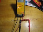
I built a 0.001 ohm shunt, the coiled insulated part is ~1 foot long of #10 solid cu. My VOM meter has 10A capability on its own. I used the meter to calibrate the shunt. It looks Ghetto but its accurate:elkgrin:

It would be of great interest to me if you could do an overlay of the graph you posted with the amperage output of the panel. Also if you could post where you are located to look at the amount of solar insolation your area is receiving during the test.
 

Attachments

  • shunt.JPG
    shunt.JPG
    52.4 KB · Views: 16

DontPanic42

Adventurer
OK, you guys have given me a lot to chew on. First up I'll go through my stuff to see if I have anything that might work. I know I'll have to hunt for resistors. Oh for the days when Radio Shack actually had electronics parts. I'll be out of pocket for a few days up in a dead spot near the Red River (no cell phone, no computer) preparing for a BBQ. While baby sitting the pit I can run some numbers prior to trying a setup. I expect I'll have a few more questions.
When I finally run a plot, I'll include the map co-ordinates.
Thanks again
 

Forum statistics

Threads
189,680
Messages
2,919,705
Members
232,700
Latest member
bradbarbz
Top