Inverter wiring questions - Suresine 300

fireball

Explorer
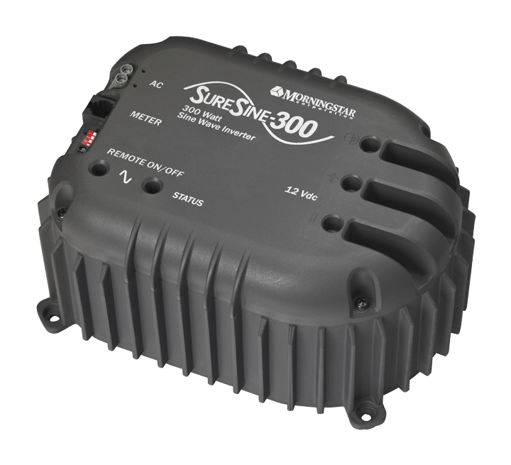
Per a few recommendations on here, I decided to purchase the Suresine 300 pure sine wave inverter for the Land Cruiser.

SI-300-220V-UL-Angled.png


In reading through the installation instructions this evening, I'm a little confused and have a few quick questions. Link to install PDF:

1. The instruction manual suggests using a 100amp fuse on the DC wiring side. This seems like overkill. It's a 300W inverter, with 600W max power. I've got a ~15-20' of 4# wire run back to a Safetyhub 100 fuse box. Will then run ~4' of 4# from the fuse panel to the inverter. Is 100 the correct fuse size?

2. I'm confused by the earth ground connection on the inverter. From some quick searching it seems some folks omit that alltogether. Some use a jumper from the white AC wire to the earth connection on the inverter. What should I do? Most folks using these are not in an auto application.... some RV, some solar powered homes, etc.

3. I'm planning to wire a GFCI outlet to the inverter using 12/2 cable. Do I need a GFCI? Where would I connect the ground? Or would I just omit?

Here is an example installation photo I found:
PowerSystemLabeled.jpg


and another, neither of these seem to have any earth ground or jumper wire:
MSCIMSC423A.jpg


Thanks in advance for any help and suggestions!!!
 

Haf-E

Expedition Leader
The 100 amp fuse is intentionally oversized in order to allow it to give the most power without the fuse blowing. Fuses should never be operated for very long above 80% of their rating as they will anneal and fail at a lower current when operated at 100% of their rating. When the inverter is starting a load it can put out the 600 watts but might have only 11 vdc coming from the battery after the cable losses - so that increases the current. Then there are the losses as well in the inverter - the datasheet says its 70% efficient at 600 watts - which it also says it can do for 10 minutes.

600W / 11vdc = 60 amps / 70% efficiency = 78 amps >>>> so a 100 amp fuse with a max recommended load of 80 amps is about right.

If you were using a DC circuit breaker it could be sized tighter (i.e. lower amperage) as if it blows it can be easily reset.

As for the ground wire - yes it should be used. Connect it to the chassis of the vehicle close to where the inverter is installed with a stainless steel bolt to some bare metal - ideally inside of the vehicle. Then put some anti-corrosive coating over the connection - like used on battery terminals. The ground wire should be at least #6 - not sure why their manual says #4 is required.

The AC output of the inverter is not "polarized" - that is neither the AC hot nor AC neutral is connected to ground - this is usually done in the AC circuit breaker panel. For a small inverter like this that doesn't have an AC input or an AC load circuit breaker panel - I would just make the connection of the AC neutral with the AC ground wire in the outlet box itself.

As for a GFCI type outlet - it is a good idea to use. Well worth the cost of putting one in.
 
Last edited:

fireball

Explorer
Haf- thanks very much for your response!

The explanation on fuse sizing makes good sense. Wasn't accounting for the 600W and possible reduced voltage. 100amp fuse it is!

I'm still a little fuzzy on the ground. Do I understand you correctly that the earth ground terminal of the inverter should be tied to bare metal inside the cabin with a #4 wire? And then the 12V battery input terminal negative(-) will be run to my ground block which goes directly to the battery (-)? Can you explain why you need to do both and why both photos of installations that I posted above wouldn't have that?

Lastly, I'm not sure where the AC ground wire in the outlet box is coming from....or going to :) How did that get there and what's the other side tied to?

Thanks a ton!
 

unseenone

Explorer
I'm still a little fuzzy on the ground. Do I understand you correctly that the earth ground terminal of the inverter should be tied to bare metal inside the cabin with a #4 wire?
On the ground, not necessarily bar metal. Most vehicles have ground lugs installed at various locations on the vehicle, that would be the idea location. On my Land Rover there are ones next to each tail light, above the rear lift door, on both sides of the engine compartment, and so on. If you can't find one, any point you can find that is solid, like a bolt in the floor might work.

And then the 12V battery input terminal negative(-) will be run to my ground block which goes directly to the battery (-)?
Yes, make sense, bolt it down.

Can you explain why you need to do both and why both photos of installations that I posted above wouldn't have that?
A lot of people don't particularly on caravans in UK, etc. but you're trying to do it right. An example of why you want it, eliminate potential RFI interference on a CB or HAM radio, or other electronics.

Lastly, I'm not sure where the AC ground wire in the outlet box is coming from....or going to :) How did that get there and what's the other side tied to?
Not clear on the question.
 
Last edited:

Haf-E

Expedition Leader
The SureSine 300 is a bit of an odd inverter in that it is not designed to UL or IEC standards - the terminals are somewhat exposed (should be in a wiring compartment) and they do not include a terminal for an AC ground conductor on the AC side. There also isn't a good way to strain relief the wiring at the inverter - so add a strap near it to prevent the wire connections from being stressed by something getting caught on the wire or even just vibration.

The two images you show are not best examples of "code compliant" installations - but they are both done on plywood sheets so in some ways grounding is potentially less of an issue. In a vehicle installation (made of metal) grounding is more important - particularly if you are powering a load outside of the vehicle with an extension cord. If there was a problem it potentially could result in a severe shock when you touch some metal part of the vehicle (under certain worse case scenarios). Neither of those installation shows any ground connections made to the inverter at all - which could also result in radio interference problems - or even malfunctioning of other electronics.

So - the AC ground wire in the AC outlet circuit needs to be tied to the vehicle chassis as well - ideally at the same point as the inverter's DC ground wire - ideally close to where the inverter is installed. Using an available ground stud is great if there is one - I've done it to tie down anchors (threaded holes into the chassis) and even seat belt bolts (which were not being used anymore after an interior conversion). Anything which has a solid connection to the vehicle chassis or even the body is acceptable. All metal components of the system should be connected together as well - so if you use a metal outlet box be sure it is connected to the ground conductors as well.

The GFCI will only protect if it has a good ground connection - so if you go through the hassle of putting one in then you'll want to make sure it has a ground wire connection or it will not work. I would use a GFCI outlet myself as it does add protection and can prevent shocks if a load is damaged or even if it just gets too "damp" inside of a load from high humidity. The only issue is sometimes they won't allow certain loads to work - but usually it for a good reason.
 

fireball

Explorer
Thanks guys for the responses! I read these on my phone on the road yesterday but needed to sit down in front of the computer to digest! I knew I didn't know a lot about electricity, but I didn't know how much I didn't know :)

The inverter will be mounted to my cargo drawer box in the back of the Land Cruiser. It will only be 2-3' from my aux panel box that I ran to that area. I have a Bluesea safety hub 100 and ran a 4# power and ground from the aux battery back to the fuse panel as shown here:
IMG_0622.jpgl.

Here is the wiring diagram from the suresine manual:
wiring diagram from manual.JPG

And here is my proposed wiring diagram after your most helpful input:
Inverter Wiring - manual diagram.jpg


The last two things I want to confirm:
1. can I safely omit the 3amp fuse on the AC line b/w the inverter and the outlet?
2. do I need the jumper wire b/w the white AC line and chassis ground?

Thanks again for the help! Nice of folks willing to share their knowledge with dummies like me :)
 

Forum statistics

Threads
190,000
Messages
2,923,003
Members
233,266
Latest member
Clemtiger84
Top