jaleel_da_sheik
Observer
Lowly Update:
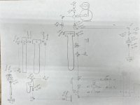
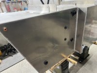
With the tanks back in the shop I was able to start fitting the components to turn them into working diesel and grey water tanks. The diesel tank/box has the following hookups: compressed air, diesel heater pickup, level sensor/sender, breather, engine diesel pickup & return, drain valve, fill port.
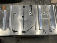
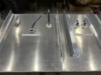
Next was the grey water tank/box. The tank had the following hookups: inspection/rinse port, level sensor/sender, effluent intake, breather, drain valve, tank defrost loop bungs, cleanout port.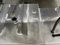
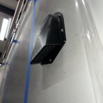
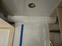
The box attached to the grey water tank had the following connections: compressed air, tank defrost loop, engine defrost loop, diesel heater & electronics port, valve electronics port, diesel heater air intake port, diesel heater exhaust port.
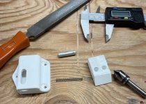
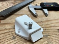
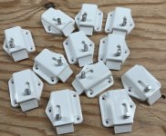
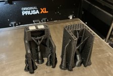
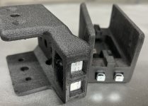
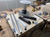
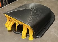
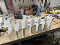
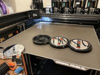
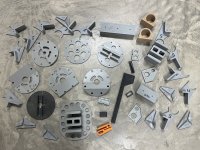
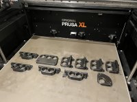
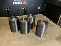
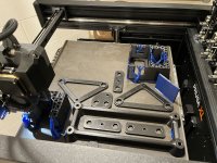
The 3D printer was once again fired up to make parts for the various pass-through components and for the diesel heater system that was going to be mounted inside the box attached to the grey water tank:
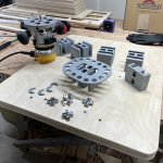
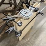
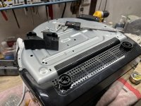
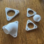
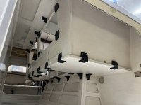
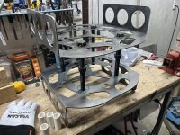
Brackets for holding the components onto the diesel system mount plate:
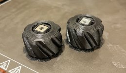
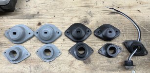
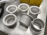
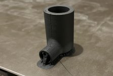
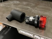
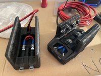
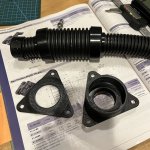
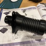
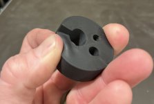
Printed a flexible dust/waterproof? seal for the fuel and electrical pass-thru:
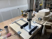
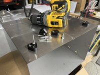
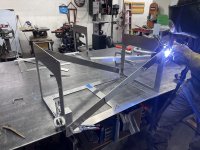
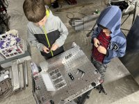
Things 1&2 were put to use assembling the heater system mount plate:
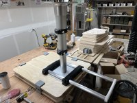
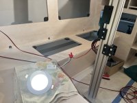
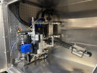
Once assembled the panel was mounted into the box:
- Sheik
With the tanks back in the shop I was able to start fitting the components to turn them into working diesel and grey water tanks. The diesel tank/box has the following hookups: compressed air, diesel heater pickup, level sensor/sender, breather, engine diesel pickup & return, drain valve, fill port.


Next was the grey water tank/box. The tank had the following hookups: inspection/rinse port, level sensor/sender, effluent intake, breather, drain valve, tank defrost loop bungs, cleanout port.

The box attached to the grey water tank had the following connections: compressed air, tank defrost loop, engine defrost loop, diesel heater & electronics port, valve electronics port, diesel heater air intake port, diesel heater exhaust port.

The 3D printer was once again fired up to make parts for the various pass-through components and for the diesel heater system that was going to be mounted inside the box attached to the grey water tank:


Brackets for holding the components onto the diesel system mount plate:

Printed a flexible dust/waterproof? seal for the fuel and electrical pass-thru:

Things 1&2 were put to use assembling the heater system mount plate:

Once assembled the panel was mounted into the box:

- Sheik
Last edited:

