MB 1120 Coming to America! Purchase, Build and Now Travel!

RAM5500 CAMPERTHING

OG Portal Member #183
Well, I guess I spoke a bit too soon about the BMS. With our previous BMS we couldn't see the individual cell voltages. Now with this JDB we can, our 400ah pack is made up of 16 100ah 3.2 LifePo4 cells from Frey in China made up in a 4P4S pack to get to 12v. One of the 4P packs (4 of the cells in parallel) now will charge to 3.65 way sooner than the others, causing an overvoltage cell alarm and charging shutoff (it rises to 3.75). This starts to happen when the cells are nearing what the BMS is saying 99% charge. Before that the voltages are all very close and seem to be in "balance". I never top balanced the cells when I got them, back then it seemed like it was an optional step just to get the most out of the batteries. Now I am seeing it is pretty much standard and required. So, at this point would you think of pulling the pack apart to top balance them would correct this or am I a bit too late?

How many times have you tried to charge the system?

Most often, all the cells and batteries take a few cycles to all balance out. It’s normal to have them slightly imbalanced and throwing codes at first, I’d guess the one throwing codes is the first in the series?

Mine took 2 cycles with the JDB BMS and now all balance perfectly

Will Prowse forums DIY solar has a ton of info on this.
 

VerMonsterRV

Gotta Be Nuts
How many times have you tried to charge the system?

Most often, all the cells and batteries take a few cycles to all balance out. It’s normal to have them slightly imbalanced and throwing codes at first, I’d guess the one throwing codes is the first in the series?

Mine took 2 cycles with the JDB BMS and now all balance perfectly

Will Prowse forums DIY solar has a ton of info on this.
We have been living on the batteries for the last 3 years. Back then there wasn't the options there are now for these better BMS's. I just swapped out my old BMS/balancers with this new JDB. Right now with a ~10 amp load at "99%" the batteries are within .013 v. But if I turn the charger on one of the 4P packs rises while the others don't. Then the BMS gets a cell over voltage and shuts down charging. I am using the Overkill Solar app to monitor, I am guessing when the "Bal" on the right of the cell graphs turns yellow balancing is occurring. I have yet to figure out how to get it to balance full time. It seems to turn off and on.
 

VerMonsterRV

Gotta Be Nuts
Just an update, thanks to help from @luthj and @DiploStrat I think I have a plan worked out. Luckily we are currently plugged into shore power (which doesn't happen very often) and the BMS with some assistance is slowly getting things balanced.

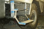
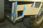
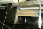
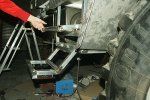
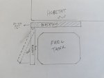
Now onto a bit of a challenge, I am revising our entry steps again. One of the goals with the new doors was to make the truck a bit more secure (I say a bit as we still have large windows). One of the other things we wished is we could retract the steps at night. This way more noise would need to be made to get in. So, I would like to add a DC linear actuator underneath the slide out platform (it is IP65 but I want to encase it in an aluminum shell to protect from elements). That is the easy bit, what would also be nice is if the same actuator could also angle the ladder in/out 22.5 degrees. This would require some sort of linkage which right now is escaping me how to accomplish. Forgive the rather crude drawing, but hopefully it will get the idea across. The challenge is when stowed the fuel tank is right below, so not a lot of room. I am considering building arms down each side of the platform inline with the ladder when stowed. A hinge could be built that would connect the ladder to these arms to hold the ladder out. So an up/down movement attached to the middle of the hinge could swing the ladder in/out. So getting the motion of the platform sliding out to cause a linkage to push down on the hinge would work. And obviously the reverse would be true. One thing is this is all exposed to the elements so simple would be the best. We are meeting with a welder/fabricator soon and he has a lathe and milling machine so we can make up most things.

PXL_20221226_182840747.jpg
 

joeblack5

Active member
If one set of 4p rises faster maybe one cell is bad or there is something wrong in the parallel wiring. I did not go back to see if you posted a picture of your configuration.
You do not mention your charge amperage. If all the connections are good then I would take an adjustable power supply and add charge to the other 4p groups untill they go into there 3.65-3.75 volt knee as well. Maybe you are only 0.5ah out and all is well.
The real determination of a full battery is not the voltage but the moment of climbing of the voltage in the knee. Obvious you have to monitor this in person in real time to shut it off when you observe it. With a 400ah pack I would not use more then 4 amp.. that would add 4 ah in one hour.
If you charger is a true current source with a shutoff then you can use it to add some charge to the individual groups...best to disconnect both your battery poles from the truck and both wires of the charger so you do not make unexpected ground loops./ Shorts
Assuming a 50amp charger that can not be adjusted lower this would be a pulse charging... 10 seconds charge..check voltage and repeat till you see the sudden voltage increase/ knee.

Good luck.
Johan
 

joeblack5

Active member
Regarding your ladder drawing..
If you mount your actuator between the platform and the tank.
Raise the ladder pivot point as high as possible on the platform or at least make the setup that the actuator pushes against the ladder so that it angles out first and make as mechanical stop that restricts that angle to 22 degrees then when the ladder stops at 22 degrees the platform will follow the rest of the movement of the actuator..

The platform has to be extended always all the way otherwise the ladder and platform will not be stable.
That means that your actuator has to be selflocking on power disconnect .

Like your platform ladder idea/ design , hope you don't mind me using that in my build.

Thanks
Johan
 

VerMonsterRV

Gotta Be Nuts
Regarding your ladder drawing..
If you mount your actuator between the platform and the tank.
Raise the ladder pivot point as high as possible on the platform or at least make the setup that the actuator pushes against the ladder so that it angles out first and make as mechanical stop that restricts that angle to 22 degrees then when the ladder stops at 22 degrees the platform will follow the rest of the movement of the actuator..

The platform has to be extended always all the way otherwise the ladder and platform will not be stable.
That means that your actuator has to be selflocking on power disconnect .

Like your platform ladder idea/ design , hope you don't mind me using that in my build.

Thanks
Johan
Thanks @joeblack5 for both your suggestions. I think with the batteries they are slowly getting closer as I repeatedly cycle them. Apparently my previous balancers (which I couldn't monitor) weren't doing a very good job. I currently have a 3ohm resistor with alligator clips on order. I will place this on the high cell restricting the current so while the other cells charge. I'll do this if I don't continue to see improvement between cell voltages. As you already know the voltage difference between fully charged and almost fully charged in LifePO4 batteries is very small.

On the steps I am working on an idea to use a "reverse motion linkage" and a "Scott-Russell linkage". I ladder will have 3 steps, with the bottom on telescoping down. The telescoping part will be manual though. So, the lever arm of the ladder would be pretty long unless the support for the 22.5 degrees is midway down. I am thinking of the hinge plate that the Scott-Russell linkage will connect to in the center of the hinge. This way the actuator will only have to hold the hinge flat with most of the force of the extended ladder being on the hinge. My plan is to get the platform and ladder built and installed. Then work on building a wood linkage to work out the kinks. Once done with the mockup, start the metal fabricating.
 

Alloy

Well-known member
Thanks @joeblack5 for both your suggestions. I think with the batteries they are slowly getting closer as I repeatedly cycle them. Apparently my previous balancers (which I couldn't monitor) weren't doing a very good job. I currently have a 3ohm resistor with alligator clips on order. I will place this on the high cell restricting the current so while the other cells charge. I'll do this if I don't continue to see improvement between cell voltages. As you already know the voltage difference between fully charged and almost fully charged in LifePO4 batteries is very small.

On the steps I am working on an idea to use a "reverse motion linkage" and a "Scott-Russell linkage". I ladder will have 3 steps, with the bottom on telescoping down. The telescoping part will be manual though. So, the lever arm of the ladder would be pretty long unless the support for the 22.5 degrees is midway down. I am thinking of the hinge plate that the Scott-Russell linkage will connect to in the center of the hinge. This way the actuator will only have to hold the hinge flat with most of the force of the extended ladder being on the hinge. My plan is to get the platform and ladder built and installed. Then work on building a wood linkage to work out the kinks. Once done with the mockup, start the metal fabricating.


Cell balancing of the JDB is only 0.05 amps. Depending on the qulaity and age of the cell it won't provide engough balancing. If the previous BMS wasn't doing a good job then I'd top balance all the cells and reassemble each bank based on the voltage/internal resistance.

I'm also wondering if the wring (equal length cable to each bank) is balanced.

Might try a wedge for the ladder that slides up and down as the platform moves in/out. The wedge would be "pulled" with roller chain attached to the frame of the truck and around a bar or roller.
 
Last edited:

VerMonsterRV

Gotta Be Nuts
Cell balancing of the JDM is only 0.05 amps. Depending on the qulaity and age of the cell it won't provide engough balancing. If the previous BMS wasn't doing a good job then I'd top balance all the cells and reassemble each bank based on the voltage/internal resistance.

I'm also wondering if the wring (equal length cable to each bank) is balanced.

Might try a wedge for the ladder that slides up and down as the platform moves in/out. The wedge would be "pulled" with roller chain attached to the frame of the truck and around a bar or roller.
The cells are all connected with plates, no wires. The balance wires are all the same length. I had read how small the balance current is. The resistors should show up tomorrow and I will give them a whirl. One of our challenges living full time in this truck is storage. I have looked into the variable chargers on Amazon, but if I bought one I would feel like I would need to keep/store it for the next time. The resistor method is tiny and would store right with the batteries. And I wouldn't need to be plugged in to work, the solar panels would take care of the charging. But then, if the resistor doesn't do the trick I'll end up ordering a charger.

My current plan with the entry platform/ladder is to get the base platform/ladder built. Then using some thin plywood try my hand at the 2 linkages I mentioned in a previous email. If I can wrap my brain around it, I should be able to come up with a working wooden linkage. Then start in with the metal work. Should be interesting.
 

Alloy

Well-known member
The cells are all connected with plates, no wires. The balance wires are all the same length. I had read how small the balance current is. The resistors should show up tomorrow and I will give them a whirl. One of our challenges living full time in this truck is storage. I have looked into the variable chargers on Amazon, but if I bought one I would feel like I would need to keep/store it for the next time. The resistor method is tiny and would store right with the batteries. And I wouldn't need to be plugged in to work, the solar panels would take care of the charging. But then, if the resistor doesn't do the trick I'll end up ordering a charger.

My current plan with the entry platform/ladder is to get the base platform/ladder built. Then using some thin plywood try my hand at the 2 linkages I mentioned in a previous email. If I can wrap my brain around it, I should be able to come up with a working wooden linkage. Then start in with the metal work. Should be interesting.

Making the cables (not the BMS leads) to each of the 4S banks the same length (from a buss bar) helps with a low (passive balancing) current BMS.

A battery charger/solar won't help because it still has to work with the low (passive balancing) current of the BMS.

You may have a weak cell in each bank that the BMS (it's 4S not 16S??) doesn't detect.

For aged cells an "active cell balancer" is better. It will take/add power between the cells vs. passive only dissipated extra power through heat.

Matching voltage / internal resistance in each cell of a 4S bank with active (2-5 amps) balancing is the best.
 

Iain_U1250

Explorer
When I was designing my steps, I used cardboard, as it is a lot easier to work with for the first concepts. All you need to do is prove the concept works, if you are getting someone else to make it, then the plywood would be great, as you could get it fully functional with all the right dimentions, as it is a bit tricky to get it working smoothly. . If you use a linear actuator, then it will lock with in position, it is a worm drive. I made mine a bit over centre, so even if the actuator comes off, the steps stay closed and don't fall down.

DSC05372.jpg

DSC05373.jpg

DSC05375.jpg

I made the two steps first, then worked out the linkages afterwards, the lower ones have slots, as the lever arm was a bit longer and it gets to the final rest position before the top step does.

DSC05380.jpg


The step have worked for the past 10 years, no idea how many cycles but when I re-greased the shafts last month, there was no wear at all.

This is how our work, if you need any details, let me know. I got the linear actuator off eBay, I have three, with different length throw, but that just means moving the mounts if I ever need to swap them over. The one I used is fully IP54 rates, and is suppose to be good for 100,000 operations,

This video shows how it works.


joeblack5

Active member
Very nice Lain,
VErmonster, good idea with a resistor, a little more work but less storage and cheaper.
I have used several bms designs and yes readout with bt or wifi is nice but I would not trust software driven bms at this point in time..
I use hardware stack active balancers and a separate chip driven bms..
I welded these stainless cases to delay potential fire situation and use Anderson connectors to quickly remove a battery.
As you can see the wiring inside is with angled cables to reduce terminal stress from expanding batteries and also from vibration. These pics are from my first experimental setup. The batteries themselves are 270ah cells.. we run two cases is series for 24 volt and then again another set in parallel. There are silicon heaters under each cell.

Good luck with the project.
Johan
 

Attachments

  • IMG_20220905_115358757.jpg
    IMG_20220905_115358757.jpg
    3.2 MB · Views: 21
  • IMG_20220831_143409837.jpg
    IMG_20220831_143409837.jpg
    3.4 MB · Views: 21
  • IMG_20220831_143402811.jpg
    IMG_20220831_143402811.jpg
    1.5 MB · Views: 20

luthj

Engineer In Residence
Active balancers can actually create imbalance on well matched packs. This is especially true if the balancer can't have its minimum delta V adjusted manually. This is because the measurement error is on the order of 2-10mv, and in the mid range between the knees, this error can result in the balancer moving energy around, when it isn't needed. Best to have it wired so that it can be unplugged completely, and only connected if needed. In your case I would just resolve the imbalance (likely from running for years with little or no balancing), and see how it behaves. Given that you have factory direct matched grade A cells, you aren't quite in the same boat as folks with commodity grade second hand market cells, which often have significant variance in self discharge.

That said, it can't hurt to have one setup so that it can be manually connected, or hardwire the harness, but leave the unit disconnected except when/if needed.

There are thousands of drop-in LFP batteries which run thousands of cycles with no issues, all with only ~60ma of passive balancing. They typically have well matched cells (such as you should have), which has a big impact. Even my A- grade commodity cells haven't needed a manual balance except once, which occurred when I had a high resistance connection which through the pack out. I often charge at 0.2-0.5C off my alternator, and cook exclusively with electricity, which often hits 0.6C discharge rates for 30 minutes at a time.
 
Last edited:

Alloy

Well-known member

Hard to go wrong with a Heltec (capacitor) balancer.


What @luthj mentions is 100%, If the balancer can't be controlled by the BMS then it should be disconnected. There's an automatic (balances at 3.4V??) version of the Heltec but I don't think it's available in NA.
 
Last edited:

VerMonsterRV

Gotta Be Nuts
The new steps start on Monday. I am trying to work out the linkage bit for the electric steps and I have a question for those more inclined to engineering.


This YouTube Video shows a reverse motion linkage. This is essentially what I want but I think I will need to have a reduction in the distance the reverse motion will travel. I am moving out the platform about 12", I am thinking that the steps will require less than 6" to swing out. So does anyone know how to accomplish this with this linkage? I am assuming that moving the center pin towards the top of this picture would make this happen?

1672430892530.png

On the battery side, I just got the resistors and will soon get the alligator clips. The JBD though is ever so slowly closing the gap with the cell voltage difference.

On another rather annoying note, I finally got the bluetooth modules for our Epever Tracer BN solar charge controllers. They were supposed to work fine together, but apparently now Epever says the BN doesn't provide enough current for them to work well. I'm going to try better, shorter ethernet cables to see if that will get them to work.
 

Forum statistics

Threads
188,201
Messages
2,903,717
Members
229,665
Latest member
SANelson
Top