Overland Hadley
on a journey
If you don't have VSC, your ABS unit sits there.
Matt,
Does your 06 have VSC?
I wish I had a big empty spot to put the extra battery.
If you don't have VSC, your ABS unit sits there.
Matt,
Does your 06 have VSC?
I wish I had a big empty spot to put the extra battery.
That was the hard part; the rest is easy…. Actually, the hardest part is finding time to finish.
Working with large diameter wiring is interesting if you’re not used to it, and don’t have the proper tools. There were occasions where I felt like I was wrestling a komodo dragon for a piece of meat. If you have a relatively strong set of cutting shears, something sharp to strip the ends (without cutting copper), and a good imagination for pulling off these ends it’ll work out even without proper tools. I used a bench vise to aid in crimping, and of course heat shrink tubing to tidy up the ends.
The National Luna kit comes with everything else necessary to wire the system together. They supply a generous amount of 16mm2 (~5 AWG) wiring, which must be cut to the needed lengths. NL also supplies a variety of lug sizes to terminate each end of the wiring, and two new battery terminals with multiple accessory posts. After considering my setup, and consulting with a few folks here on Expo, I decided to upgrade to 2 gauge wire for all the connection points. This was primarily because of the winch, and the potential for large current draws if I string the batteries together. This may never become necessary, but it certainly gives me piece of mind.
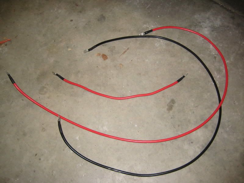
Three new battery wires are necessary, all cut to fit my implementation; a red lead from the primary battery to the NL solenoid, another red lead from the solenoid to the auxiliary battery, and a ground wire between the two batteries. In my case, about 28", 78" and 80" for each wire.
(exciting picture of wires...)
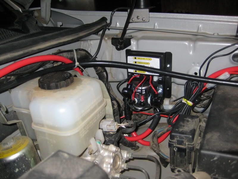
The beauty of the NL design is that you don’t have to touch any of the factory wiring; no cutting, no splicing, no rewiring (except for mods already added), and no fuss. The instructions do a nice job of laying out different options and ideas for implementation depending on the specifics of your system. I took the NL recommendation to keep the winch wired directly to the primary battery. This will keep 99% of the winch duty on the primary battery and alternator, reserving the auxillary battery for everything else and backup starting duties.
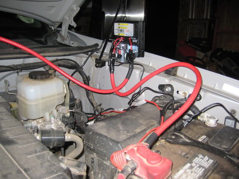
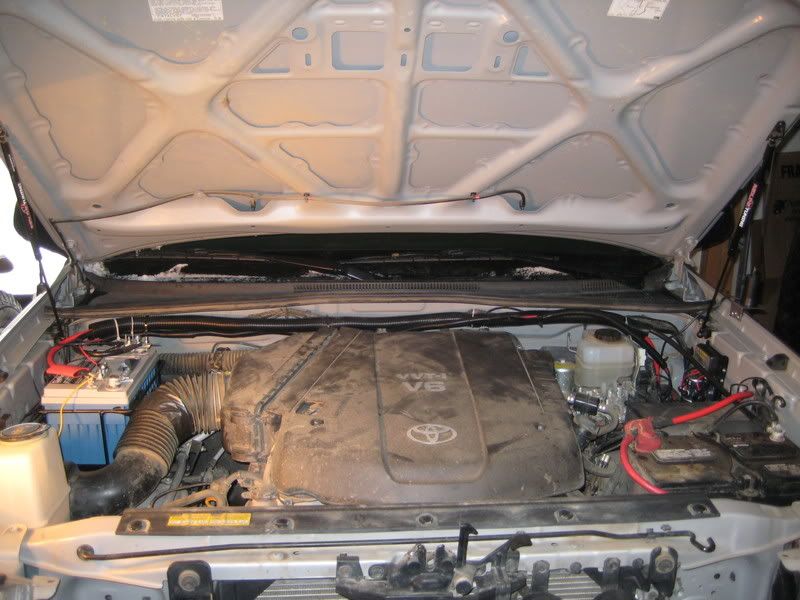
With everything ready to go, I roughed in the system.
So far, so good.
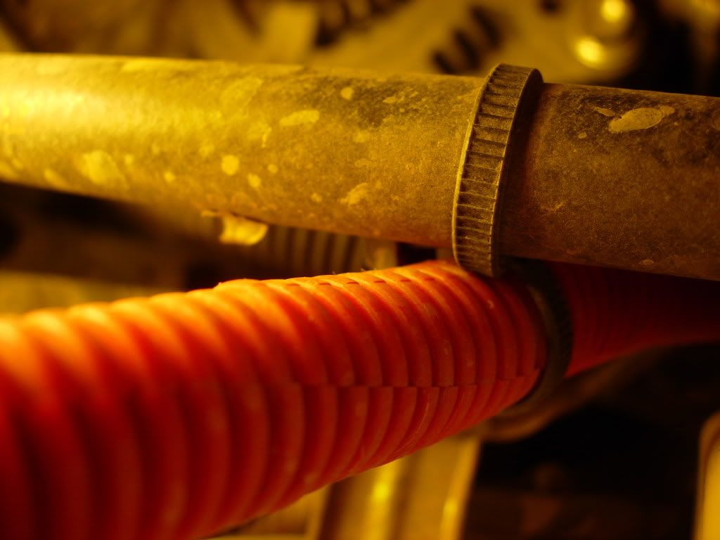
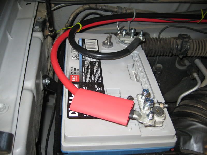
I guess I'm 98% done at this point. I pulled all the wiring for the aux lights and the HAM, rerouted them to the aux battery, and put them in their own loom. I cleaned up and ran a loom for the + and - cables between the batteries (along the back of the engine bay). I pulled the front grill for clear access to the winch wiring, and put the two wires into a loom and added some grommets where they pass through to the main battery.
I still want to put some red conduit around the short leads from the primary battery to the winch and solenoid, but I'm not too worried about them at this point.
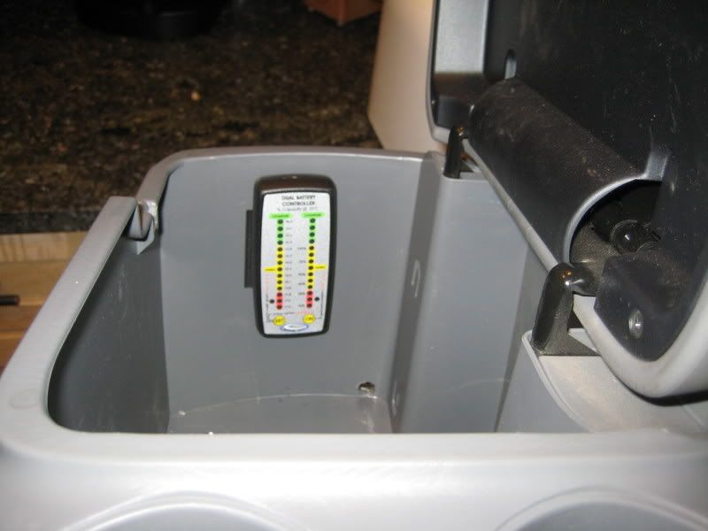
For the controller, I decided to run the wires under the dash and through the center console. I drilled a small hole in the bottom of the console box, and I'm using some industrial velcro to hold the controller against the side of the box. So I can pull it out as needed to check the battery levels, but its not always out and on display and cluttering the dash.
The major remaining item in this setup is to run one large lead from the aux battery to the back of the cab into a fuse block, where I can then add accessories as needed. With that setup, I'll add some 12 volt outlets in the cab, and at least one in the bed - finally laying the infrastructure to install everyone's favorite Expo accessory....
