Partial re-wire of my trailer - need help please

rayra

Expedition Leader
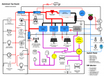
The transfer switch is an interlock that guarantees you cannot backfeed shore / grid power when you are using an alternate power source, be it generator or solar. It is specifically in place to prevent the potential electrocution of electricians working in a grid-down emergency.
Thus if you are using shore / grid power you should have a wiring and device setup that ensures that when those alternate power systems are in use no power can be connected to the grid.

The transfer switch is a code requirement in residential electrical code when you are adding the capability to energize your residence with a generator.

You can obviate that somewhat by isolating your 12v systems such that your solar and batteries feed them and your grid-powered battery charger is 'one way', cannot backfeed on the supply side. and with the transfer switch locking out the grid in order to enable the generator connection.

Your 110VAC systems should be arranged to be powered by that grid / shore power and again be interrupted by a transfer switch before they can be powered by a generator.

And likewise any use of a 12v-powered inverter to power your 110VAC system. Using the same interlock, if possible. Design your systems so you MUST lock out the grid to feed any power into your 110 systems.

I also didn't see anyone mention 'right sizing' your inverter. Inverter(s). There a good bit of power loss via heat in an inverter. A lot of power loss running a 2000w inverter capable of pushing 18A to run an very low-consuming device. So put whatever low power needs you have on the 12v side, and only put the heavy loads on the 110VAC side. But beyond that, if you are going to be running off batteries and an inverter you do not want any heavy loads unless you absolutely must. If it's to make anything hot, go propane. I'd even suggest a propane fridge for a long-term living arrangement. 110VAC fridge is easy in a grid environment. it's a power-expensive choice in an off-grid one.
 

rayra

Expedition Leader
ho one other things what is the meaning of the double lines 40A in the upper right side of your diagram - do you mean two parallel runs fused at 40A each, for that stack of 15A fused circuits? Seems a terrible idea unless those two 40A runs only merge at the terminal lugs at each end of the run. And even then I don't like the idea of parallel sub-total-potential-load runs, even if one can 'get away with it.'

Any design that depends on a human action or everything working just right is a bad design. Re-do the design to eliminate those potential failure points.
 

Chorky

Observer
yep put the converter on its own breaker, so it wont be powered by inverter and thats often the only way to shut it off if you need to work on DC side while plugged in.. working on the DC power system when the air con is on is super nice, trust me.

Your Gen and Inverter are two seperate things, coming in two different ways.. you Generator is hooked to your 30A main shore power circuit through the normal shore power pigtail.. that feeds right to that main 30A breaker and from there is distributed into smaller 20A/15A circuits for your air conditioner, converter, wall outlets, etc.. Your Inverter is going to be tapped inline to your wall outlets, after the wall outlet circuit breaker and will only switch over to the inverter when that main 30A feed has gone dark.. its transferring the circuit out of that dark circuit box and over to your inverter.. you will be able to test failover/and failback by simply flipping the breaker on the wall outlets, turn it off and you'll hear the ATS click and inverter fans ramp up.. then flip breaker the other way and after another click the inverter will ramp down.. you can do this under heavy load and it'll never notice switching back and forth between the inverter and the shore power.

colloquially, the big 30A pigtail power cord coming out of your trailer is 'Shore Power'.. and Shore Power is your external AC power source, it can be either/or normal 120VAC mains, or a portable Generator.. it dont matter really until you have a big onboard generator on an RV with a big fuel tank, and then that adds a whole bunch of complexity because your dealing with starters and another transfer switch and computers to have it automatically fail over from Shore Power to Onboard Genset to Inverter and fail back.. If you have an onboard auto starting generator you have little need for the inverter really unless you need to keep everything running while the genset ramps up.

Hmm. ok so I'm still having confusion then. say the inverter is connected to the post switched side of the outlet breaker (and lets also assume that the converter has been given its own breaker). I'm confused on what still would prevent backfeeding power. Howevever, I'm not sure how a ATS is wired either so that might be adding confusion...

The only way I can think this works is this - power comes from shore, goes through the ATS, to the breaker, and then to, say, fridge. Meanwhile ATS is also connected to inverter. So when shore power goes away, ATS internally 'switches' and opens the shore circuit, and closes the circuit coming from the inverter, and thus the inverter senses load and ramps up. Maybe this is how the ATS is wired? Since I've never seen one...

With the latter being said, can a ATS be wired to as to provide power to, say, the outlet breaker, ac breaker, and microwave breaker? Not that I would want to use them all at once of course, or really probably at all. If I wanted to use anything other than the fridge and computer than starting the genset would be best. I'm just curious in terms of how they are wired.
 

Chorky

Observer
And likewise any use of a 12v-powered inverter to power your 110VAC system. Using the same interlock, if possible. Design your systems so you MUST lock out the grid to feed any power into your 110 systems.

I also didn't see anyone mention 'right sizing' your inverter. Inverter(s). There a good bit of power loss via heat in an inverter. A lot of power loss running a 2000w inverter capable of pushing 18A to run an very low-consuming device. So put whatever low power needs you have on the 12v side, and only put the heavy loads on the 110VAC side. But beyond that, if you are going to be running off batteries and an inverter you do not want any heavy loads unless you absolutely must. If it's to make anything hot, go propane. I'd even suggest a propane fridge for a long-term living arrangement. 110VAC fridge is easy in a grid environment. it's a power-expensive choice in an off-grid one.

Locking out from the grid is exactly what I wanted to do. For 2 reasons, 1 being that obviously my generator or an inverter trying to power the 'grid' would never work and probably cause something to burn up, and 2, even if it could, I wouldnt' want to be trying to power the entire town ha!

If you check out my first post, one of many many questions I have is in fact sizing of the right inverter. I'm taking a total guess that 2000w would be about right to say power the fridge, and computer or other small items.

As for the mention of ther 12v systems. My thoughts would be that a solar charger (such as a Zamp 30?) would be wired to the direct output of the converter so that it provides charging to batteries, and service to 12v components, and that when it 'sees' power from the converter from shore power, the solar charger would essentially stop charging.

Also, I do fully realize and agree that a propane fridge might be better. However, my factory propane/AC fridge has died 3 times already. Because of it I have been living with a 66L 12v fridge. I've had zero luck in the standard "RV" fridge. After reading and researching from many other fulltimers, I made the decision that a residential style 120v fridge is the better way to go. It's a risk... Hopefully it works out. It's also cheaper... Because of my RV fridge and it's problems, over the course of 3 years I have probably lost a total of 2,000 bucks in food. And always at the worst of timing too. Given the money, I would have opted for a 12v option.

ho one other things what is the meaning of the double lines 40A in the upper right side of your diagram - do you mean two parallel runs fused at 40A each, for that stack of 15A fused circuits? Seems a terrible idea unless those two 40A runs only merge at the terminal lugs at each end of the run. And even then I don't like the idea of parallel sub-total-potential-load runs, even if one can 'get away with it.'

Any design that depends on a human action or everything working just right is a bad design. Re-do the design to eliminate those potential failure points.

So in my diagram about this, basically on the factory power there are in fact 2 40a fuses, which further feed into various fuses (15a) for various 12v coponents. My assumption is that 1 40a fuse feeds the top half circuits, and the other 40a fuse feeds the other remaiing circuits. I cannot verify this yet becaueys I haven't taken it apart yet and haven't seen a circuit board diagram of this particular box. The funny thing is there are a total of 11 available 12v fused power points. Only 7 are currently used, and they are all 15a fuses. It's cheap factory garbage, so the fuses probably aren't even proper reflection of the actual devices. So basically I drew the diagram how it is because I dont' know for sure how those double 40a fuses play a role.

Now, to further complicate matters, it is interesting to note that the furnace (12v), water heater propane side (12v sensors, etc.), and water pump (12v) all do not have any fuses anywhere that I can find. Nor switches. Well, the pump and water heater do of course on the wall, as does the furnace intergral with the thermostat where you can turn it off, but there are no other independent switches like I would imagine. So these 40a fuses could in fact be powering those items...
 

Chorky

Observer
I just found a diagram that shows those 40a fuses both being reverse polarity fuses. Not sure what thats all about to be honest.
 

rayra

Expedition Leader
To spare you the electrical reason how it works...
Simple answer is reverse polarity fuses protect the charger/converter incase its battery gets accidently connected backwards.
Btw,
Connecting things backwards is fairly common in trailers.
Black wire is often used as a positive conductor, white as negative.
And that's a carryover from residential wiring, where black is the conductor, white is a neutral / common and green is an earth ground. vs Automotive where red is typically positive and black is negative / ground.
I've used black as some positive runs in my vehicle, but I've followed national electrical code and flagged most ends of such runs with red tape, adjacent tot eh connector. Ironically my phat new red-insulated 1/0 alternator came with black heatshrink on the ends and I didn't bother to put red tape on it. It's right in the open, 18" long and runs from the ALT connection to the tiny red junction box where all the positive battery cables are. I's 'obvious' and easy to trace, so I shrugged.


OP, I'd give strong consideration to starting your wiring setup with your grid service panel connection to your trailer being fused in the junction box and then connecting via a corded plug to an outlet/inlet on your trailer. with your 110 stuff connected in the trailer to that. And then create double-ended plugged cable for your generator that must go into that same outlet. Such that only one of them can be plugged in at a time. And your solar system and it charge controller connected right to your battery array. And then any 110VAC-based charging method you have to your battery array have the positive feed connected to the battery array via a properly rated diode. That way your solar can stay connected and the solar charge controller will sense the full charging voltage of 110VAC-based batter charger and will not charge the batteries. And the diode will prevent the batteries and solar from backfeeding the shore power connection.
And/but if you want to harness all the solar power you can to reduce your shore power usage, then all your power using needs to be sourced from your batteries with you only connecting to shore power when you need to re-charge your batteries. But that means running a 12vdc->110vac inverter all the time.
There's plenty of 'smart' devices now that OUGHT to swap power sources, say when grid power goes down, but can you trust them to switch / isolate properly. They cost a lot more than a breaker.

You have to consider what your heirarchy of needs / desires and craft the system to meet them. What's the most important aspects you need to address. Sounds like in the short term it's prevention of backfeeding the shore power connection. So design for that. And later if you lose shore power your generator becomes the source. Or that's when your inverter takes on the 110VAC duties and your generator is used primarily as a battery charger. Or you live like a real 'off grid' house and you time your high power demand activities in conjunction with your generator runs to max your battery bank.
 

dreadlocks

Well-known member
Maybe this is how the ATS is wired? Since I've never seen one...

It is exactly how its wired, its basically just a multi-pole relay if you know what that is.. COM = Outlets, Normally Closed (NC) = Inverter, Normally Open (NO) = Circuit Box.. when the relay is energized by the circuit box, COM-NO are connected, otherwise COM-NC are connected.. its really simple, the ATS just puts it in a nice case with a plug for the inverter for the electrical novice.. but you could build one very easy with a double throw double pole 120VAC coil relay and power the relay by the same source you want to switch too.

Size your inverter for your biggest expected load, I went with a 1000W inverter and its more than enough to run my dorm sized 850W microwave oven, or my 700W coffee maker.. but I specifically went with low power, mini devices.. a normal Microwave Oven or Keurig/Coffee machine would expect to have at least 1500W at its disposal, a 2000W inverter would run anything off that outlet that you could normally.. but if its going to spend most of its time running a TV set at 5% load its going to be rather inefficient on the power front.

I'm hoping you can setup a super oversized solar array at this remote site your gonna be living at, even if its not all on your roof and you have to build temp stands for em onsite.. otherwise your gonna be running that genny an aweful lot and should seriously consider every ounce of efficiency you can squeeze out, if that means a DC or LP fridge then u should do it.. its gonna take at least 6-7h of engine time to restore battery to full, and if you're collecting too much solar than your battery will take you can burn it off by running other appliances like laptop chargers, box fans, ice makers, tool chargers, etc when the sun is cooperating and power is abundant..
 
Last edited:

dreadlocks

Well-known member
attached is a simple diagram of my trailer, its needlessly complicated but the important thing to look at is the AC power and the ATS..
 

Attachments

  • Intech Discover Wiring - Simple (5).png
    Intech Discover Wiring - Simple (5).png
    322.5 KB · Views: 14

dreadlocks

Well-known member
@buddha I paid a bit extra for my victron.. its got one of the best standby current Ive found coupled with very respectable efficiency and surge ratings.

@Verkstad yeah I use some big ass solar 15A diodes in a few places to keep from backfeeding a few things... its mostly what I had laying around but the specs fufill my needs and everything seems to work well.. Use em to isolate my tow vehicle from the trailer's charge sources, my over-ride switches that need to not backfeed other devices when the power is cut, and finally its how I hooked up both my AC/DC Shore Charger and Portable Solar Panels's external port up to my SmartSolar without em ************** with eachother.. I'm using my SmartSolar as a programmable DC-DC charger for both Solar and AC inputs.. I made a thread on that here: https://www.expeditionportal.com/forum/threads/guide-victron-mppt-smart-shore-solar-combined.210404/
 

Chorky

Observer
OP, I'd give strong consideration to starting your wiring setup ....

You have to consider what your heirarchy of needs / desires and craft the system to meet them. What's the most important aspects you need to address. ...

So after nearly taking my genset apart all the way, I realized its more work than it is worth, at least right now, to hardwire it to the trailer. So the plan will still be inverter, solar, and genset, but likely I will have to plug the trailer into the genset if/when I need to run it. Maybe later on if I find I truly am using the gen often, but for now I'm not going to hard wire. It is not an open frame style, so it's rather difficult to access the internal wirings unfortunately.

As for the most important aspect to address - honestly the absolute most important aspect is keeping the fridge running - all the time. I can, if necessary, run the genset every night for a while to recharge things what the solar might not - but all the other items, really, are not nearly as necessary. I'm tired of loosing food ha. And the rest of the items in the trailer really dont even need to run when I'm away. So maybe it is safe to say that just the one 15a breaker circuit (all outlets minus AC and microwave) should be charged via the inverter.


Size your inverter for your biggest expected load, I went with a 1000W inverter and its more than enough to run my dorm sized 850W microwave oven, or my 700W coffee maker.. but I specifically went with low power, mini devices.. a normal Microwave Oven or Keurig/Coffee machine would expect to have at least 1500W at its disposal, a 2000W inverter would run anything off that outlet that you could normally.. but if its going to spend most of its time running a TV set at 5% load its going to be rather inefficient on the power front.

I'm hoping you can setup a super oversized solar array at this remote site your gonna be living at

This is one question I have still, and following into other discussions. Sizing inverter and batteries. If I simplify things, and say only 'need' to keep the one 15a breaker charged, that would simplify things - and in a factory trailer, that might be best as well until I either build a house or a custom trailer... Now, it would be nice to have the option to run the microwave (1350w in, 950 out), but not necessary by any means. So if, though, I were to also consider a few other minor things, such as the computer and monitor, then I'm guessing a 1000w inverter would suffice? According to the website, the spec of the fridge is only a 0.91a pull, which is less than the computer or monitor. I have a suspicion that's not an accurate number though.

As for an oversize solar - I figure I can fit 510 w worth of panels on the roof. I'm not sure that a huge array not mounted to the trailer would work - at least for the next few years. Maybe after that - but at which point I may be looking to other living options. In any case, I think I will be limited to 510... But I"ll have to take roof measurements.

Thank you for the wiring diagram by the way. That really helped me understand (I'm visual), and makes much more sense now. So aside from sizing inverter and batteries - Am I still correct in that solar should go to the output of the converter? Seeing as how the converter is already wired to the batteries it would reduce a long wire run.
 

dreadlocks

Well-known member
Solar gets wired into its own charger controller, your converter cant handle it.. you have a solar charger, thats hooked directly to the battery bank.. look at Victron SmartSolar, huge bang for your buck.

The sweet spot for leaded solar is 200W per 100AH, about ~15A ideally but more likely ~10-12A.. so that would be considered oversized for a pair of 230AH GC2's with ~39A ideally, but more than likely 30-35A which is a good size charge.. you also have to consider what loads are going to be ran during the day? If your computer is pulling 300-400W, and your solar is getting 400-500W its going to sustain charge but after all day in the sun its not going to restore much charge with whats left... If you add more AH bank than that with the solar you have available you'll be hard pressed to gain grounds without absolutely perfect solar and no day time loads.

The good thing is batteries bulk up for such a short period, so once the battery is taking only a little fraction of a charge your other loads the solar can sustain are nearly battery free. the bad news is solar inputs tend to fluctuate on a hour by hour to day to day basis and unless your in a fixed position with good area cleared for year-round suntime the nomadic lifestyle just horridly complicates things and is going to push your genset up to primary energy source, and solar to secondary..

You may need to seriously consider getting or leveling up real fast and learning to build a Lithium bank.. thats going to cut your gasoline needs down dramatically.. with two LFP's you could run your genset for 2.5h dumping 80A charge in, restoring ~180AH of battery to get you through the day or you could run your genset for 6-7h dumping 2-30A in a pair of GC2's and restore a piddly 120AH in that time.. if your willing to deal with maximum of 2.5h of genset a day, usually much less cuz solar is helping out or taking daytime loads off the bank.. that would give you basically a 180AH a night diet, which is rather large for even a full timer.. I dont have computers but I do have enough that when I'm a glutton for power I can barely use half that recreationally.
 
Last edited:

rayra

Expedition Leader
That reminds me I need to put my laptop on my Kill-A-Watt. Been planning to get a camper trailer and drag it around the nation and the big pig of a desktop PC and four monitors will NOT be going along.
But I am intending to set two batteries matching what I use, into the trailer and likely keep it plugged into the bumper plug to my underhood Aux, giving me three grp78 batteries to suck on overnight. Limited microwave, laptop / TV / DVD. With a couple additional panels on the trailer roof. Dual / redundant solar systems, both around 200W. Leave and secure the trailer and drive the Sub somewhere, I've still got both systems functional when the trailer and vehicle are severed. And for good or ill I could return to the camper and with a full(er) Aux and jack the trailer in and there'd be some 'leveling', if the trailer solar hasn't done its thing during the day.
What I really want is one of those small quiet Honda generators and with a bi- or tri-fuel and be able to connect it to the trailer propane so I could throw a bulk charge on the trailer batts if necessary. And the 200A+ ALT I've added ought to make quicker work of recharging the run-down Aux.
I'd expect to arrive at the next National Park with everything fully charge, for each short stay.
 

burleyman

Active member
I have used these small manual knife blade type transfer switches to choose and separate sources. Copper conductors. Sources on the ends, loads fed from center. Break before make. In my case to choose shore or inverter. Shore can be grid or generator. Disconnects both hot and neutral.


Chorky

Observer
Dreadlocks - your pictures help me tremendously, thank you.

Ok, so how about this for wiring then, slightly different than my original thought and based on everyone's thoughts
  • Starting from shore power, installing a second wire directly to the genset. Both genset and shore connected to a 30a (or maybe slightly higher for safety) ATS, then to the main power unit
  • Inverter (not sure if I need 2000w or not, 640w may be sufficient) from the battery (or converter output to reduce wire runs) to the GFCI and standard breakers (excluding AC and elec. water heater) to allow all outlets ability to run if necessary (including microwave)​
  • Though the inverter would be connected to the pre-switch side of breakers, it would go through another ATS - assuming this is possible
    • in other words, 2 ATS total, one for main system from shore/gen, second one for inverter input​
  • Add a 5a (even available?) standard breaker specifically for refrigerator outlet so if necessary all others can be turned off and fridge on​
  • Add breaker to separate outlets from converter so converter has own breaker (mostly to prevent the 'circle' of power that would just burn battery power as earlier suggested​
  • Add 12v fuses for furnace, 12v side of water heater, and water pump​
  • Use RV 12v wires for a temp controlled exhaust fan to remove any excess heat behind residential fridge​

Some side points
  • Currently the fridge outlet is not GFCI - which it should be considering its proximity to potential water, but the wall vent is going to be sealed so it doesnt matter much anymore I suppose
  • The GFCI circuit doesn't even work anyway... I tested it yesterday, it wont turn off in a water event
  • My 12v fridge now is being used as a deep freezer but connected to the 110v currently until I get another 12v plug put in (outside)
  • The new refrigerator pulls 0.91a at 180w, significantly less than the RV fridge AC side....spec rated at 2.7a 440w!
  • The RV fridge was burning, literally. Upon removal, it was apparent it nearly started a fire. All ammonia had escaped due to fully rusted lines - not sure why...
  • New fridge is working pretty well thus far although I'm a little dissapointed in the actual temps (thermometer inside) - install was easy comparatively - and there is more room than I know what to do with!! I cant believe I've lived with a cooler size 12v fridge for 4 years!

Some clarifying questions
  • So lets say i have done the above current ideas. Would it work fine enough to have the inverter connected to the output side of the converter? Since the converter has a wire all the way to the batteries anyway, it would save a wire pull.
  • Along with this, I would assume inverters are smart enough in that when they do not have an appliance trying to pull power, theyre automatically of and thus not converting power, correct? In other words, if shore power is on and working, the inverter would be automatically off and not making the converter work extra since there is plenty of shore power.
  • Along these lines, solar can also be connected to the output side of the converter? Also to allow for less wire runs but also to allow a direct connection of solar to inverter (instead of 20' to the battery, and then 20' back to the inverter) for less power loss?
  • Any suggestions for specific parts? Since I'm obviously not even knowing of the ATS from the first page of this thread? Maybe a medium grade level since this trailer is a make do unit for now?


Some pics
SDVB6535.JPG

IWBA4535.JPG

GZUX7453.JPG
SO MUCH ROOM!
 

Forum statistics

Threads
188,500
Messages
2,905,863
Members
230,501
Latest member
Sophia Lopez
Top