pivoting frames and mounting campers

Sitec

Adventurer
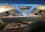
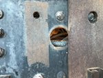
While pulling the living body I have apart for mods, widening etc I've been giving this 3 or 4 point mounting thought. The central 1 or 2 pivots that have to sit in the middle of the chassis between the two rails have to have decent allowable twist movement so the bush system (pictured a couple of posts up) is perfect IMO, as its greasable, allows free movement of the chassis to twist etc, and is very similar to the picture I had in my mind. What I am pondering though is the two outer chassis pivots that stop the body from falling to the left or right. These are usually roughly in the center of the body (one either side of the chassis) with the chassis internal pivots at the front and rear (on a 4 point system). On mine, I'm having the 2 fixed points near to the cab about a meter back from the front of the living body (purely so the walkthru stays roughly in line both sides. My thoughts are that even with the truck fully crossed up and the chassis twisted (100mm to 150mm chassis twist over 6 meters), there will be very little movement on the outer two mounts. With this in mind, I now plan to utilize two 50mm (2") holes (pictured) that are approx 1 meter behind the cab and roughly central in the chassis 'C' section. I'd have a pair of drop plates off the body (200mm x 16mm) plate?) which would have a machined boss the same size as the holes in the chassis. I'd then have a brass bush/boss that slid into the two holes and a large central bolt that goes through the center of the brass boss, with two large washers. This would be mirrored on the other rail, and would locate, clamp and hold the brass in place, form a rigid solid fix that still allow the small amount of twist flex on this front mount... Thoughts? It saves me drilling holes, utilizes an existing hole that'll act as a pivot...

515094
 

Sitec

Adventurer
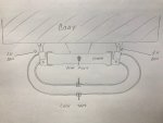
Hi brains trust. Going on from 4 point mounts. I've settled on my 2 fixed outer points being 'up front' as per my last post, with two central chassis pivots behind. One in the center of the body and one at the rear. To add to this system, I'm thinking of adding two rams on the outside of the chassis at the rear, which are linked to the body. When on decent roads, the taps are closed locking the rams, stopping body roll, but when off road, the taps are unlocked allowing the chassis to twist and flex without stressing the body. Thoughts? Sketch attached for reference.

525047
 

Coachgeo

Explorer
think you would just have to test that... could do that with just air bags too..... one bag or ram gets compressed as chassis is pushed toward the box.... that would send air/fluid to the opposite ram making it extend approx. same amount as the other side was compressed....... net result keeping the box level-ish.....

could also put a cab level (ride height) valve on it and use that to activate an air pump to maintain the air suspension . Read up on big rig air "cab" suspensions. Note... All of them have a shock AND an air bag on each side. Sometimes the air bag is built with the shock inside.... with out knowing this in advance some images/video's will confuse you.
 

billiebob

Well-known member
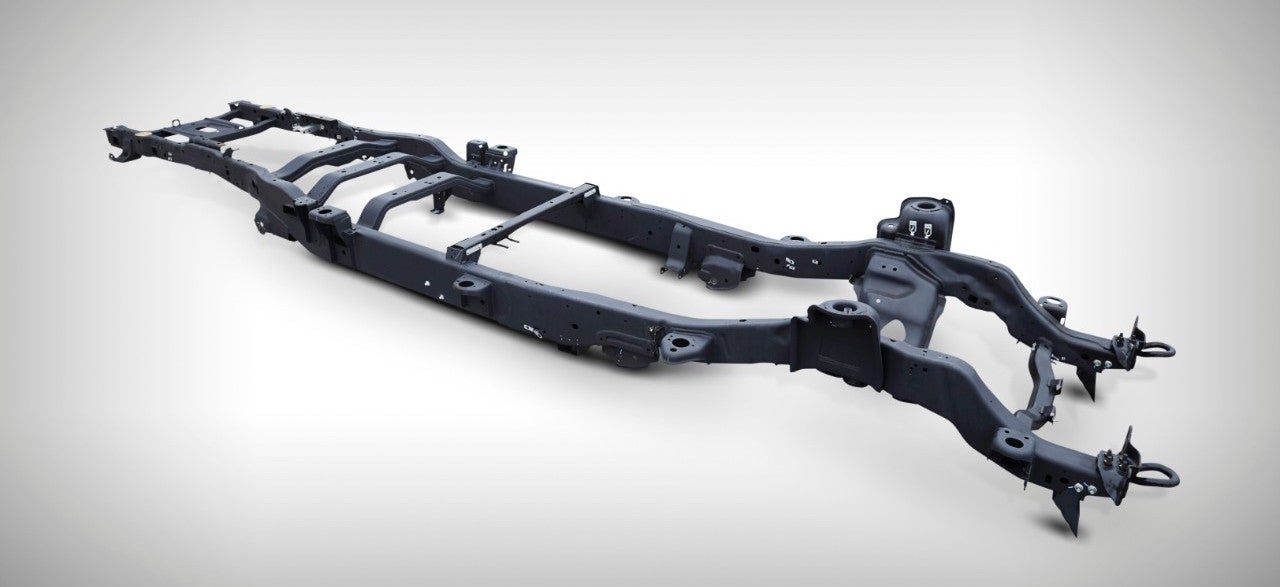
Your OBS PSD doesnt have a boxed frame under the cab.

Not sure when the change happened, but my 2011 does.
It creates a much more rigid platform for the cab to ride on.

From cab-forward it is a combination of boxed and open C
Cab-back, is all open C

Like so...

2017-ford-f-series-super-duty-frame-04.jpg


And 2017 and newer receive the new, fully boxed frame.

1444971194976954509.jpg


Whereas, the older nearly 100% open c-channel looks like so....

attachment.php
I'll take the early open C channel everytime.
 

Darwin

Explorer
I went with a captive spring mount in the front on my cab chassis 3500. Unfortunately I don't have any pictures of the mount and because the boxes are in the way now I am unable to get a good shot of the mounting system. If you want, you can check out some photos and videos of it being built on Instagram @mountainguildoverland

He did a really nice job building the bed and the mount.
 

C p weinberger

Active member
Check out everlanders build on YouTube, he uses semi brake hydraulic pucks to secure body to frame when on tarmac and releases to drive off-road, I don’t know anyone else who uses this system, but this guy is a guru of gurus and Seems to really think through his systems before implementation
 

Coachgeo

Explorer
Check out everlanders build on YouTube, he uses semi brake hydraulic pucks to secure body to frame when on tarmac and releases to drive off-road, I don’t know anyone else who uses this system, but this guy is a guru of gurus and Seems to really think through his systems before implementation
been digging thru his videos for a good while to finaly find they info your refering too. so others do not have to dig as long

See at about 6'15" into video

at 11'42" into video is most of the detail. Vewy intewesting
Could this be utilized in a captured spring set up...... net result being captured spring with a locking mechanism essentially? Must be huge springs inside those cans for 6" of travel. Would just need a way to keep box from moving port or starboard while articulating. Many ways to do that and is common in captured spring setups.
 
Last edited:

javajoe79

Fabricator
Does anyone have a good source for an insulator between an aluminum box and a steel subframe? I was thinking of using polyurethane body mounts in 8 spots but have decided I would rather have the box rest on the subframe directly with some sort of foam or rubber as an insulator then use 8 bolts with the same rubber under washers, top and bottom, to hold the box in place. That way I don't have points loads at each bolt, the bolts will just keep the box located horizontally. Does that sound right? There are numerous options on mcmaster for rubber and foam and I'm probably overthinking it but I don't want to have to redo it.
 

billiebob

Well-known member
Check out how the cab/sleeper mounts on a semi truck. Maybe just use semi components which are air ride.
 

javajoe79

Fabricator
I just found a good rubber resource after my last post. The prices I was seeing elsewhere seemed high for just basic rubber strips. I emailed this place and got a very quick reply and price on exactly what I wanted.

http://www.equalseal.com/product-p/c-60neo-250-3-25psa.htm

Check out how the cab/sleeper mounts on a semi truck. Maybe just use semi components which are air ride.
No need for that complication. It's the camper box, not the cab. I have considered it for the cab but have yet to take issue with the ride quality so it will stay as it is for now.
 

Motafinga

Adventurer
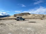
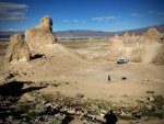
Figured I would add to this old thread with a design I came up with for an OBS F250 using a Tool Bed and an Alaskan camper.I got some great info from this thread during my research.
There are more a lot more details in the build thread in my Sig line for anyone interested.
 

Attachments

  • sub frame .JPG
    sub frame .JPG
    729.7 KB · Views: 147
  • urban flex 2.JPG
    urban flex 2.JPG
    469.2 KB · Views: 147
  • truck eureka dunes.jpg
    truck eureka dunes.jpg
    547.2 KB · Views: 132
  • truck pinnacles 2.JPG
    truck pinnacles 2.JPG
    541.9 KB · Views: 108

Ramdough

Adventurer
Hi brains trust. Going on from 4 point mounts. I've settled on my 2 fixed outer points being 'up front' as per my last post, with two central chassis pivots behind. One in the center of the body and one at the rear. To add to this system, I'm thinking of adding two rams on the outside of the chassis at the rear, which are linked to the body. When on decent roads, the taps are closed locking the rams, stopping body roll, but when off road, the taps are unlocked allowing the chassis to twist and flex without stressing the body. Thoughts? Sketch attached for reference.

View attachment 525047

That is not how a four point works. They are in a diamond shape. What you are describing is a three point with an extra rear pivot. That will be bound up before you start and will generate huge forces on the rear pivots.

Also, your hydraulic system would potentially add torsion to your torsion free frame defeating the purpose. I have thought of doing similar for in road only to stiffen things up, but don’t like that you have to remember to open the valves before going off-road.


Sent from my iPhone using Tapatalk
 

Sitec

Adventurer
That is not how a four point works. They are in a diamond shape. What you are describing is a three point with an extra rear pivot. That will be bound up before you start and will generate huge forces on the rear pivots.

Also, your hydraulic system would potentially add torsion to your torsion free frame defeating the purpose. I have thought of doing similar for in road only to stiffen things up, but don’t like that you have to remember to open the valves before going off-road.


Sent from my iPhone using Tapatalk

Hi Ramdough. Well, all but the lock outs/hydraulic system are built. I have the two outer pivots no more than 100mm from the rear hanger of the front springs about 400mm behind the cab, keeping the cab and body faces in a fairly similar plane at all times. I have two central pivots, the first is located on the rear springs front hanger cross member and the second on the rear spring rear hanger cross member. These are all tack welded to the body and are yet to be fully welded. I've since added another central pivot at the very rear of the truck. All pivot points are on the center line of the chassis. I have then twisted the truck chassis (rear lh dual wheels 400mm off the ground) to the point where the lower lockers just touch the body to check that it all worked without any of the tack welds going bang, which it did. To double check what you mentioned about binding, I then unbolted and removed each locking bolt in the pivots and tapped each pin with the hammer to see how much load they were under. To my surprise they would tap out with ease and have minimal to no load on them. I must have got something right! :) Re the hydraulic setup, I have gone away from this due to weight, the time involved and cost to do it. I now plan to utilize 2 (poss 4) stumpy 100mm x 100mm coil springs between the body and chassis these will be sat with no or minimal tension when the truck is flat, and will only be compressed as the chassis twists. Here's a pic of the chassis twisted and the body straight. it was in this position that the pins would tap out. :)

Mid Mounts 6.jpg
 

Forum statistics

Threads
188,153
Messages
2,902,870
Members
229,582
Latest member
JSKepler
Top