JRhetts
Adventurer
Tests, Diagrams, and [?] A Plan
I think gait is getting pretty close to the nub. Nice job from so far away. [Maybe being upside down isn’t really detrimental to one’s thinking ;>} ]
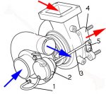
My first diagram below shows the structure and the parts of the overall turbo/waste gate assembly.
1= compressed air line as input to waste gate actuator
2= waste gate actuator housing [not openable, and practically inaccessible]
3= actuator rod
4= waste gate housing
5= waste gate valve arm

My working hypothesis is that it functions like this: increasing pressure thru 1 at some point causes mechanism inside 2 to move arm 3 to operate valve arm 5, which in turns opens the waste gate valve inside 4, which reduces exhaust flow over the turbine blades and lowers overall boost back on the compressor side.
That’s all for now, folks.
John
I think gait is getting pretty close to the nub. Nice job from so far away. [Maybe being upside down isn’t really detrimental to one’s thinking ;>} ]
My first diagram below shows the structure and the parts of the overall turbo/waste gate assembly.
1= compressed air line as input to waste gate actuator
2= waste gate actuator housing [not openable, and practically inaccessible]
3= actuator rod
4= waste gate housing
5= waste gate valve arm

My working hypothesis is that it functions like this: increasing pressure thru 1 at some point causes mechanism inside 2 to move arm 3 to operate valve arm 5, which in turns opens the waste gate valve inside 4, which reduces exhaust flow over the turbine blades and lowers overall boost back on the compressor side.
That’s all for now, folks.
John
Last edited:

