Replace AGM house battery to LifePO4?

luthj

Engineer In Residence
I doubt that overloading a 370 amp alternator is going to be a problem, particularly as the max current for this battery is 160A.

Anyway, the smartest option would be to hook this up to the alternator using the existing wire and see what happens. If the issue is drawing too much current and having the BMS shutdown, adding a section of smaller gauge wire or an extra fuse may fix that for only a few $. Most likely a DC-DC charge will not be needed, but on the off chance it is, it can be added later. It would seem silly to spend (a lot) of money in a charger when there is a good chance it is not needed and it may actually slow the charging of the battery.

Took the words right out of my mouth.


...

Do you have a non lithium starting battery? What kind of configuration do you have you current battery bank in terms of supporting electronics? Also care to elaborate on the lithium pack?

My starter battery is a standard AGM unit (8 years old?). My current bank uses an outback mate/monitor/inverter/solar charger. I plan to configure it with a single main contactor, and a DIY BMS. This will be combined with ~300AH of lithium prismatic cells. I will use a simple charging relay (200A unit). This relay will be switched manually, and also by SOC/voltage (via the aux relay on my battery meter). With my alternator being between 13.7-14.1V, its perfect for rapid charging of lithium. I may need to use a slightly smaller fuse (or a smaller wire section) to throttle charge rates. I have run my alternator at 100% output near idle for 100hours or so. No issues to date, it just cuts back the voltage a bit to stay under its current limit. If my 500AH Agm bank at 30% SOC can't damage it, I doubt a lithium pack will.
 

dwh

Tail-End Charlie
The op lists a 370A alternator, so overloading seems like a minor concern.

Huh. Didn't see that. Well, if that's what he's got, then the issue (as Rando says) is overloading the battery and tripping the BMS.

So in that case, no need to limit to 30a.

If the battery specs say a max of 160a, then it would seem a 120a DC-DC would be better. But Battle Born recommends .5C for longevity, even though 1C is max continuous.

Does Aims do the same? 160a max, but 80a recommended for longevity? If so, then for a Sterling unit, 60a might be better.


And sure, as I said, current could be limited by monkeying around with wire sizes, but I have my doubts as to the idea of taking a #2 down to a smaller size to reduce current.

First, I'd be worrying about blowing fuses and burning wire, but also I wonder just how precise one could get using that method. Might take a lot of trial and error (and burned wire and fuses) to get it dialed in.

Might just be better for a guy who can afford a 370a alternator (which never goes above 14v? ******?) and an $1800 battery to just drop a few hundred extra on a proper charger.
 
I really appreciate all the input. It sounds like I have some missing facts that I need to confirm before making any decisions.

-Confirm battery resting voltage and dead battery voltage for this Aims Power battery
-Confirm what current the battery prefers for longevity

Also just to confirm the general consensus is that even if the battery manufacturer suggests a charging voltage range LiFEPO4 doesn't really care if the voltage is a bit lower? It will not effect the longevity of the battery?

I am really not sure why everyone seems to think that lithium batteries need DC-DC chargers. Relative to lead acid batteries lithiums care a lot less about 'correct charge profiles' give them a voltage between 13.6 - 14.4 and they will charge, shut it off if it goes over 14.4 (or the BMS will do it for you). They don't care about multi stage charging or float charging or any of the rest of that lead acid nonsense.


If your alternator outputs 13.8v, that would get your LiFePO4 battery up to 80-90% SOC and stay away from the 'knee' in the charge profile which can cause balance issues. I have my Victron MPPT solar controller set at 13.8 for my LiFePO4 bank, and it works well. Even with my anemic 13.6V output alternator and a long run of skinny wire my 150Ah lithium will still charge at ~10A from the alternator, which is plenty for me.


The easiest option for charging from your alternator would be an ignition controlled relay (you can probably rewire your National Luna to work this way) so that the lithium charges with the car running and is isolated when it is off. However you should add a battery monitor and the Victron BMV-712 has a fully configurable relay output that could be used to control the solenoid between the starting and house batteries then you can set the combine/isolate voltages to what ever you want. Also note that if you add the Victron Smart Battery Sense to your battery, then the Victron MPPT can be configured not to charge below a certain temperature.

I actually do have the Victron BMV-712. I didn't show it on the diagram since it wasn't for charging. So the relay on the BMV-712 would control a solenoid that would replace the National Luna? I think I'm following... when the truck starts the voltage increases so the battery monitor knows to close the relay then when the truck turns off the voltage decreases and then opens the relay?

I doubt that overloading a 370 amp alternator is going to be a problem, particularly as the max current for this battery is 160A.

Anyway, the smartest option would be to hook this up to the alternator using the existing wire and see what happens. If the issue is drawing too much current and having the BMS shutdown, adding a section of smaller gauge wire or an extra fuse may fix that for only a few $. Most likely a DC-DC charge will not be needed, but on the off chance it is, it can be added later. It would seem silly to spend (a lot) of money in a charger when there is a good chance it is not needed and it may actually slow the charging of the battery.

So I'd want a current limiting fuse? Don't think I've ever seen one before.

My starter battery is a standard AGM unit (8 years old?). My current bank uses an outback mate/monitor/inverter/solar charger. I plan to configure it with a single main contactor, and a DIY BMS. This will be combined with ~300AH of lithium prismatic cells. I will use a simple charging relay (200A unit). This relay will be switched manually, and also by SOC/voltage (via the aux relay on my battery meter). With my alternator being between 13.7-14.1V, its perfect for rapid charging of lithium. I may need to use a slightly smaller fuse (or a smaller wire section) to throttle charge rates. I have run my alternator at 100% output near idle for 100hours or so. No issues to date, it just cuts back the voltage a bit to stay under its current limit. If my 500AH Agm bank at 30% SOC can't damage it, I doubt a lithium pack will.

Care to share what simple charing relay you plan to use? Also how and when would you manually switch it and what settings would you apply to the battery meter for SOC/voltage?

Might just be better for a guy who can afford a 370a alternator (which never goes above 14v? ******?) and an $1800 battery to just drop a few hundred extra on a proper charger.

Haha yeah not sure if I should be dumping this much into my battery system without a job traveling around but thought if I've been able to make my current AGM last 5 years while still preforming ok that the LifePO4 would be a smart investment. Also I'm with you on the "which never goes above 14v? ******?". I'm considering purchasing a multimeter that has both AC and DC current reading to see if the altenator is really pushing out what claims.
 

luthj

Engineer In Residence
So I'd want a current limiting fuse? Don't think I've ever seen one before.

A fuse is basically a calibrated resistor, one that will blow over a certain current. In fact, small electronics design often uses resistors as fuses and vice versa. Because fuses need to meet a spec they are really consistent. Think of the resistor as a restriction nozzle on a faucet. They produce a voltage drop (pressure drop analog). Reducing the voltage at the battery (at say 100A) you can then select the fuse that keeps your current at a reasonable level. Generally this is still well under the fuses rating, so it will get slightly warm, but not blow.


Care to share what simple charing relay you plan to use? Also how and when would you manually switch it and what settings would you apply to the battery meter for SOC/voltage?

I was thinking of a Blue sea remote battery switch. They are quite meaty. There are many commercial 12V relays that can handle 100A+, so pick on based on your expected max current. Then I would use a triple pole dual throw switch. One position is off, the other is auto, and the other is manual on. Auto would run through two sources. The first is the engines D+ signal (activated when the engine is running), and the second would be the battery monitor. When the monitor detects the battery as full (via return current or absorb voltage/time), it would remove power from the relay. This prevents overcharging.


You can grab a clamp-on DC ammeter fr around 50$, its a great tool to have. Note that you will not see 370A of current unless you have a big load on the alternator.

If you have a decent multimeter, you might set it to AC voltage, and see if your alternator is putting out clean DC or not.
 

Rando

Explorer
I really appreciate all the input. It sounds like I have some missing facts that I need to confirm before making any decisions.

-Confirm battery resting voltage and dead battery voltage for this Aims Power battery
-Confirm what current the battery prefers for longevity

Also just to confirm the general consensus is that even if the battery manufacturer suggests a charging voltage range LiFEPO4 doesn't really care if the voltage is a bit lower? It will not effect the longevity of the battery?

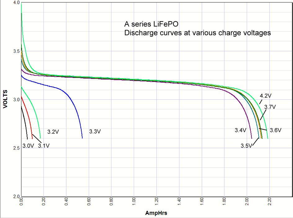
LiFePO4 batteries all have essentially the same voltage curves - a fully charged resting voltage around 13.2V, fully discharged voltage around 12.8V. LiFePO4 won't care if the charge voltage is a little lower. Powerstream has a great article on this here: https://www.powerstream.com/lithium-phosphate-charge-voltage.htm . The takeaway point is summarized in this plot (note these voltages are per cell, so multiply by 4 for your battery:
life-discharge-series-a.png


What this is showing is that any charge voltage above 3.4V *4 = 13.6V will get your battery above 90% full, and anything below about 13.2V won't charge your battery at all. So there is really no need to take that battery up to 14.4 or whatever the maximum voltage is - with one caveat, some internal BMS only do cell balancing when the cells are above 3.6V. So once a year or so it may be good to get the battery up to 14.4V ( you can use solar for this) to allow the cells to balance.

I actually do have the Victron BMV-712. I didn't show it on the diagram since it wasn't for charging. So the relay on the BMV-712 would control a solenoid that would replace the National Luna? I think I'm following... when the truck starts the voltage increases so the battery monitor knows to close the relay then when the truck turns off the voltage decreases and then opens the relay?

No need to replace the National Luna, just disconnect the solenoid from the 'brain' and drive the solenoid from the relay on the BMV-712. In the app, set the 'High start voltage relay' set to ~13.7V and the clear value to 13.4V. When the truck is running, the voltage will rise above 13.7, closing the relay on the BMV which will then close the solenoid. When it is of the voltage will drop back to the LiFePO4 resting voltage of 13.2 which will open the relay and solenoid. You can also set the relay to also act on the house battery voltage to allow your solar panel to charge your starter battery via solar once your house battery is full.

So I'd want a current limiting fuse? Don't think I've ever seen one before.

How much wire between the alternator and the house battery? I am almost certain that there is enough wire there to provide sufficient current limiting. But you should have a fuse at both ends anyway, so if you need to add a little more resistance a fuse is a safe and easy way to do this - they are fundamentally low resistance resistors. Definitely just try connecting the lithium battery up first and see what happens. The BMV will show you how much current is flowing, and the battery BMS will shut everything down before anything bad happens.

Care to share what simple charing relay you plan to use? Also how and when would you manually switch it and what settings would you apply to the battery meter for SOC/voltage?


Haha yeah not sure if I should be dumping this much into my battery system without a job traveling around but thought if I've been able to make my current AGM last 5 years while still preforming ok that the LifePO4 would be a smart investment. Also I'm with you on the "which never goes above 14v? ******?". I'm considering purchasing a multimeter that has both AC and DC current reading to see if the altenator is really pushing out what claims.
 

luthj

Engineer In Residence
Using a fuse to produce a known voltage drop is pretty effective. Obviously you need to include the wires voltage drop as well.

Here are some common fuse resistances when cold. They give a voltage drop reference as well. Putting two of the 100A fuses on a wire run will add 0.180V of drop. Combined with wiring, that can be enough to drop your Alternator from 13.8V down to 13.5V. Which would dramatically cut charging current to a lithium battery. With some minor testing, you can easily swap in the fuses to find one that will limit your charging to 150A or similar. Obviously stay under the limits for the wiring you are using, and the fuse itself.

 
LiFePO4 batteries all have essentially the same voltage curves - a fully charged resting voltage around 13.2V, fully discharged voltage around 12.8V. LiFePO4 won't care if the charge voltage is a little lower. Powerstream has a great article on this here: https://www.powerstream.com/lithium-phosphate-charge-voltage.htm . The takeaway point is summarized in this plot (note these voltages are per cell, so multiply by 4 for your battery:
life-discharge-series-a.png


What this is showing is that any charge voltage above 3.4V *4 = 13.6V will get your battery above 90% full, and anything below about 13.2V won't charge your battery at all. So there is really no need to take that battery up to 14.4 or whatever the maximum voltage is - with one caveat, some internal BMS only do cell balancing when the cells are above 3.6V. So once a year or so it may be good to get the battery up to 14.4V ( you can use solar for this) to allow the cells to balance.


No need to replace the National Luna, just disconnect the solenoid from the 'brain' and drive the solenoid from the relay on the BMV-712. In the app, set the 'High start voltage relay' set to ~13.7V and the clear value to 13.4V. When the truck is running, the voltage will rise above 13.7, closing the relay on the BMV which will then close the solenoid. When it is of the voltage will drop back to the LiFePO4 resting voltage of 13.2 which will open the relay and solenoid. You can also set the relay to also act on the house battery voltage to allow your solar panel to charge your starter battery via solar once your house battery is full.


How much wire between the alternator and the house battery? I am almost certain that there is enough wire there to provide sufficient current limiting. But you should have a fuse at both ends anyway, so if you need to add a little more resistance a fuse is a safe and easy way to do this - they are fundamentally low resistance resistors. Definitely just try connecting the lithium battery up first and see what happens. The BMV will show you how much current is flowing, and the battery BMS will shut everything down before anything bad happens.

Very interesting. So below is a picture of the cells that make up this battery. They specify the rated voltage as 3.2v per cell. Does that mean the 12.8 is probably accurate then compared to say the BB and most other LiFEPO4 cells at 13.2?

Capture.JPG

Thanks for the tips on the National Luna working with the Victron battery monitor. The wire connecting the starting battery to the house battery is 2 gauge and is about 18ft long. Most calculators I tried to use have an option of single wire system or 2 wire system. Would I choose 2 wire system since their is a positive and negative wire between both batteries? Here are the results below with 2 wire specified and 13.8v with different currents:

Untitled-1.jpg

I'm now seeing I need to get some concrete numbers from my truck. I'm gonna just get a meter capable from amazon that can read DC current. When measuring the voltage and current from the altenator do I need to disconnect the battery or anything? Or just measure at different RPMs?
 

luthj

Engineer In Residence
You need to apply a load to see what the alternator will produce. The engine battery should never be disconnected.

Using an inverter or similar, put around a 100A load on the system, and make sure the charging relay is closed. Measure the voltage drop between the alternator and battery. Measure the current (clamp on DC meters make this easy).
 

Rando

Explorer
My DIY 150Ah lithium battery is made from essentially the same cells - the charged resting voltage will be around 13.2V. The 3.2V is 'nominal' like 12V is nominal for a lead acid, even though they are closer to 12.6 - 12.8V when charged.

Based on your calculations below, I would guess your charge current will be on the order of 30 - 50A, assuming your alternator stays at 13.8V with that sort of load.

Very interesting. So below is a picture of the cells that make up this battery. They specify the rated voltage as 3.2v per cell. Does that mean the 12.8 is probably accurate then compared to say the BB and most other LiFEPO4 cells at 13.2?

View attachment 531780

Thanks for the tips on the National Luna working with the Victron battery monitor. The wire connecting the starting battery to the house battery is 2 gauge and is about 18ft long. Most calculators I tried to use have an option of single wire system or 2 wire system. Would I choose 2 wire system since their is a positive and negative wire between both batteries? Here are the results below with 2 wire specified and 13.8v with different currents:

View attachment 531791

I'm now seeing I need to get some concrete numbers from my truck. I'm gonna just get a meter capable from amazon that can read DC current. When measuring the voltage and current from the altenator do I need to disconnect the battery or anything? Or just measure at different RPMs?
 

Forum statistics

Threads
189,112
Messages
2,913,095
Members
231,761
Latest member
stone23
Top